A very kind chap at ITV Jersey found the footage of my interview with ITV immediately prior and post my test flight …. It also shows my very FIRST a landing at Jersey ! (Thank you so much Andy Fox)
What is really nice is the interview they did with my Dad .. sadly gone now … such a lovely lasting memory and lovely to hear his words
Now the engine is back and running beautifully I’ve run into some annoying snags related to the wiring ..
The majority of the working was prepared and fitted around 7 years ago … it consisted of a number of looms with the bizarre but obligatory all white cabling … for every single device !
Slightly bucking the trend of aviation wiring I made a few of the connections colour coded .. so Red for power, Black for earth ..so, at a glance you pretty much knew what a wire was serving … then added the odd colour into the predominantly white looms. Yellow was oil pressure, Orange was oil temp, RPM was Blue….
The 3 looms were to provide a degree of separation for the primary engine monitoring instruments …. The mags … and the radio, the aim being to keep any ‘noise’ (a black art in itself) away from things like radio
Due to the very small panel space of the Ranger, I opted for a number of 2 1/4” dials, the main one being the engine monitor … serving up 2 x CHT, 2 x EGT, Oil pressure, Oil Temp and RPM as well as Hobbs.
This unit has 2 D plugs in the back …and even the instruction manual says you ‘may’ be provided with a male or female D Plug for the Thermocouples … the manual is also pretty unclear as to which way you are looking at the numbered pins … so is it Male or Female .. and is it viewed from the plug as you hold it in your hand ‘facing you’ or .. even more bizarrely … with the plug covers off .. facing away .. as if you were soldering the plug together !
Anyway, having had the engine in and out more than a few times over recent months AND taken the opportunity to rip out the old connector block .. that worked fine…just looked like the B and Q part it was ! .. I’ve got a misreading CHT and EGT a and going round and around to try to resolve the issue
Having roped in 2 sons to run through my recursive sequence and confirm I’m not going mad …. We have asked another friend to give his input …
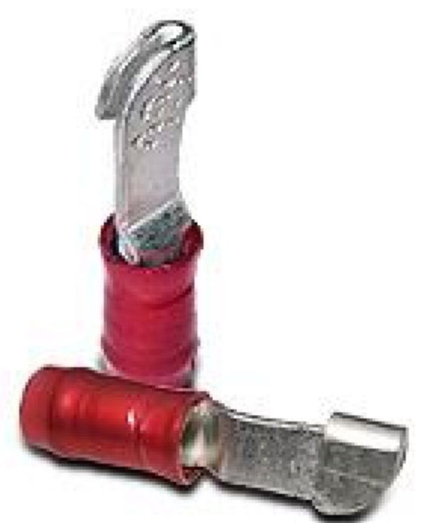
Having reviewed and removed the question arises of WHY did I put quite so many handshake connectors in ! I loved the flexibility doing this on first fit .. being easily able to connect and disconnect things BUT … for each thermocouple and each earth and each live and each oil and pressure sensors … I have multiple ‘interrupts’ in the supply lead
Each of these points, over time, can become a bad joint … can get corrosion … suffer from my initial bad crimping (documented elsewhere .. using the wrong tool) … or just simple not like being pulled apart after years … I think st this latter part that has UPSET things the most !
Looking to simplify this setup … I’ve worked out that from PiN D plug to thermocouple end point … my ‘current’ setup has joints, as follows , PIN, a handshake at around 10” .. so 2 joints, a Ring connector at the firewall side connecter block - so 2 joints, and now, double ALL that for the positive and the negative ..so 10 connection point’s in all …. NOW plan is to reduce to 2 !
Now, extrapolate that up … 4 thermocouples … 40 connection points, reduced to 8 … will now slowly work back through the system to refresh AND reduce the connections