Another little bit …

Some of the repairs are for bits that weren’t directly caused in the accident.

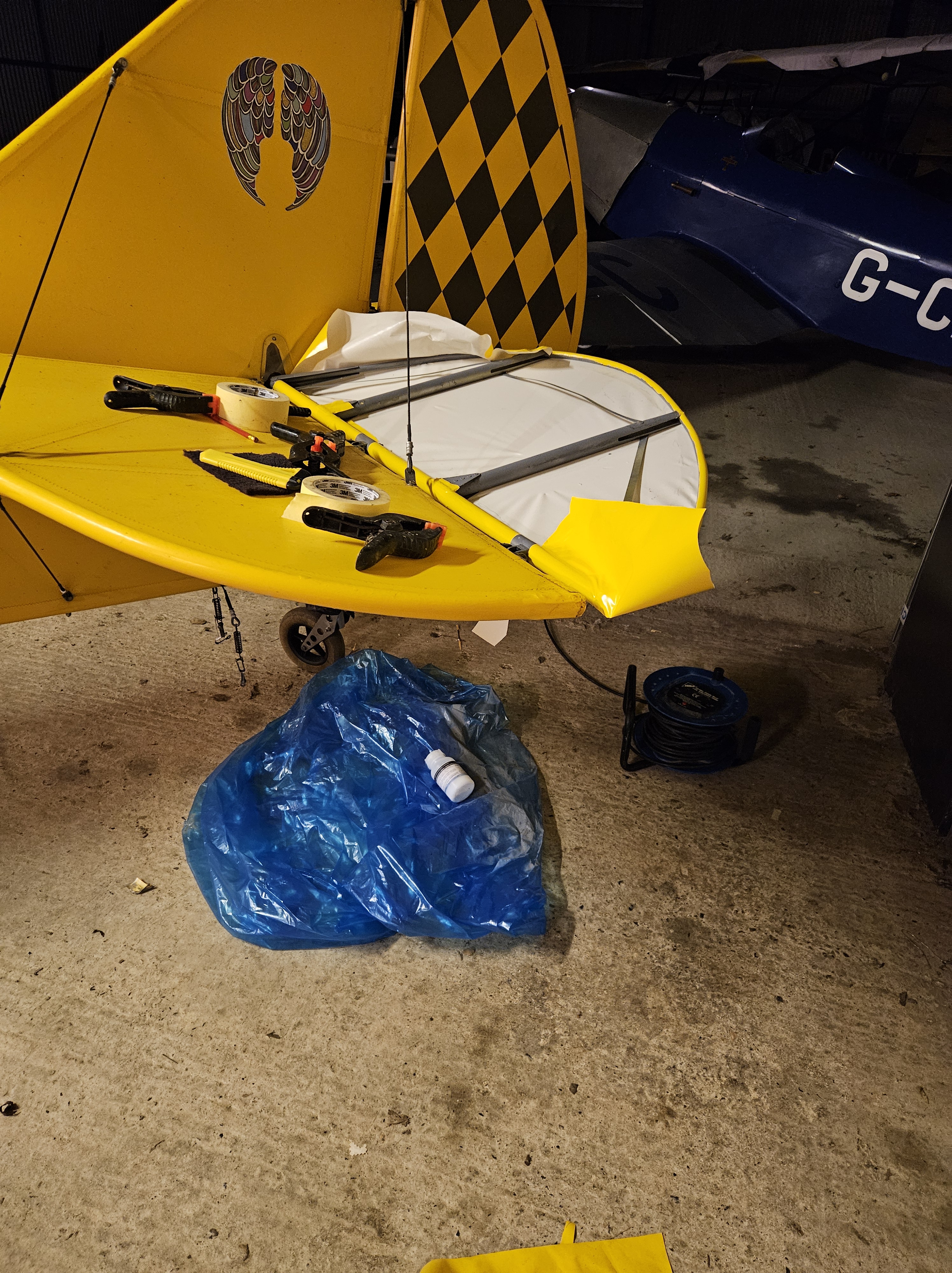
The port elevator was part that got the material scraped in the hoist recovery…trying to repair the scuffed material was proving a bit tricky so decided to strip and recover. At last the ambient temperatures have risen above freezing so allowing gluing to continue.

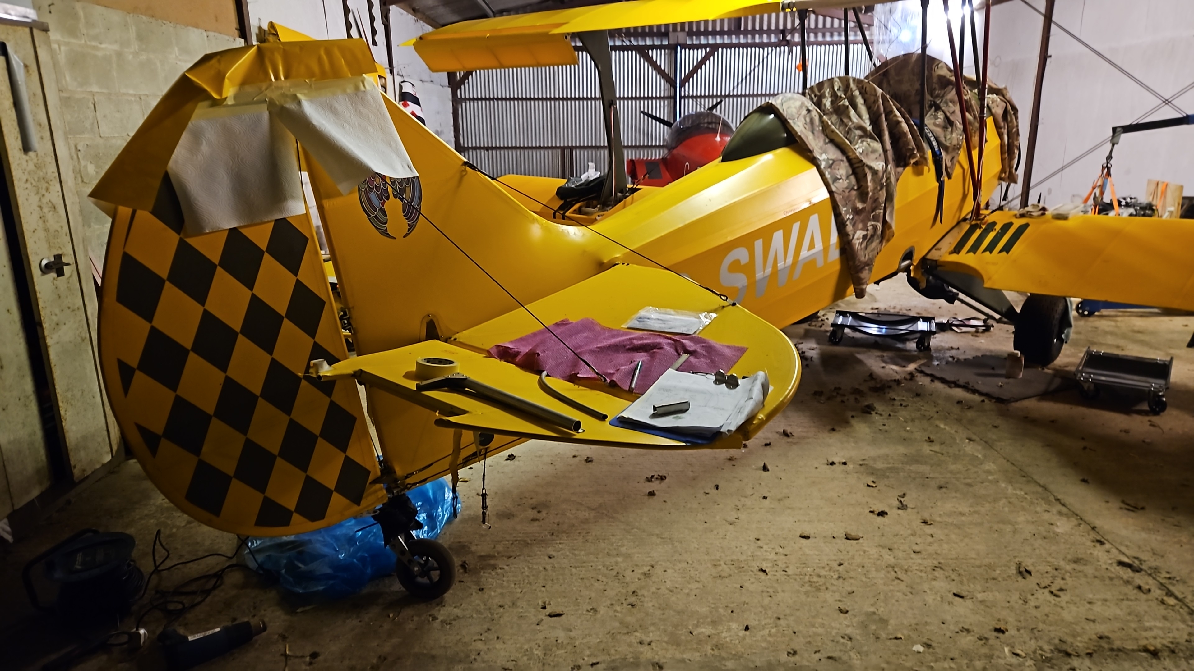
The top of the rudder showed a small crease in the material as it tipped over, so was stripped back to check.

No damage was located so the material was terminated on the top rudder rib and the metal cleaned and prepped for a small repair panel.

It’s a bit of a pain that the diamond pattern in Olive green has now been slightly trimmed ..but may ne able to source a s.all section from the Jersey company that did the original. Remember them saying they couldn’t guarantee the rudder diamond pattern sections wouldn’t peel off at speed ! They have lasted VERY well !❤️

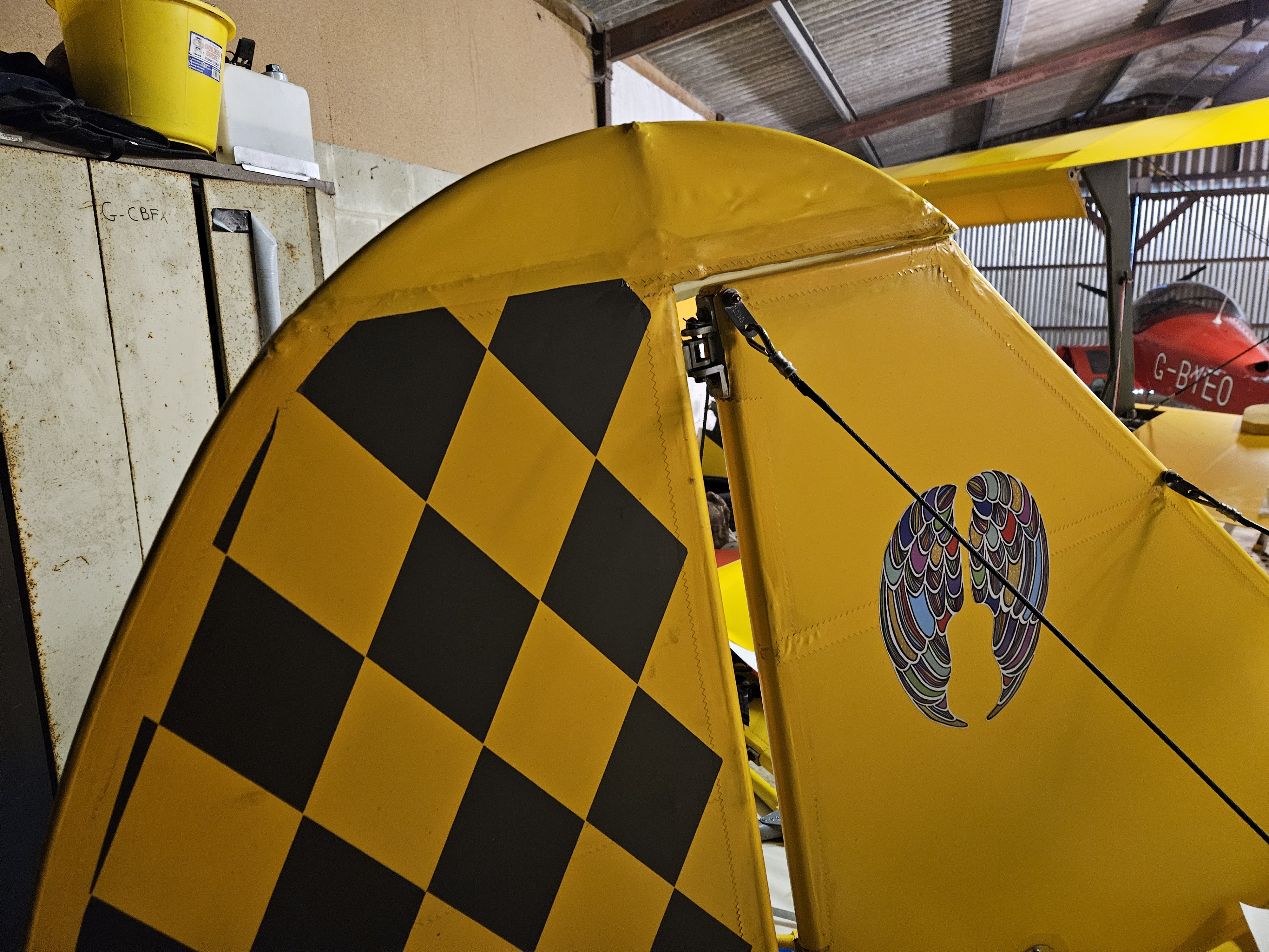
Not too bad ‘pre shrink’ .. will let it all cool and harden and do the other side before applying heat shrinkage to tighten

Still flippin’ cold !

A busy weekend with home bits but managed to get up to the hangar to start the new setup and position of the radio antenna

The original was smack in the centre of the upper cabane as this was largely an open structure bound by 2 capped ply edge ribs and a centre rib. The whole thing was covered in 1mm Finnish ply and beefed up in the centre which a ply mount for the antenna.

The new upper alloy spare dump tank means that the open structure has gone but the large aero shaped tank is slightly slimmer (at the edges) and so allows space for an offset mount of the new (replaced) antenna .. the other , although probably fine, was bent through 45′ as the aircraft flipped.

I don’t really want the antenna in the body although that could be a logical location..the original, with its upper cabane location and large baco foil style landing plane gave me solid reception up to just short of the Isle of Wight from Jersey at just 2,500 – 3,000′

I’m planning on using the same foil and sandwich idea to get good connectivity

Engine – Finally have all parts

Now that I finally have collated all the parts associated with the new engine fit i can remove it for the exhaust make up.

The local company who are going to be doing this work are an amazing set of engineers who support a whole range of enthusiasts and industry covering classic cars as well as manufacturing incredible items such as Spitfire and Hurricane exhaust stacks !

The assembled parts include:

  • Exhaust kit (Czech supplied) with straight tubes, O ring angle rings, springs and silencer box
  • Lightweight oil can that fits very snugly between the rear of the engine and the firewall
  • The large (French sourced) water radiator – this will mount on support brackets underslung under the main body of the engine
  • A much smaller (than previous) oil cooler – actually found someone in UK to supply this ! And the the support arms that will place this right behind the front cowl ‘mouth’ intake

To make it easier for the engineering company to work on things (and they originally suggested perhaps taking the aircraft to them), I decided to make a cradle for the engine to mount in, and try to represent Firewall forward.

This should give them the body line as well as lots of room to work as they assemble the parts in situ and bracket up.

At some point, and now with ready access to the rear of the engine, I can look to heat up the water pump mounting bolts and feed pipes and realign 2 of the pipe exits so that the rubber coolant tubes miss the engine mount bolts.

Blog at WordPress.com.

Up ↑