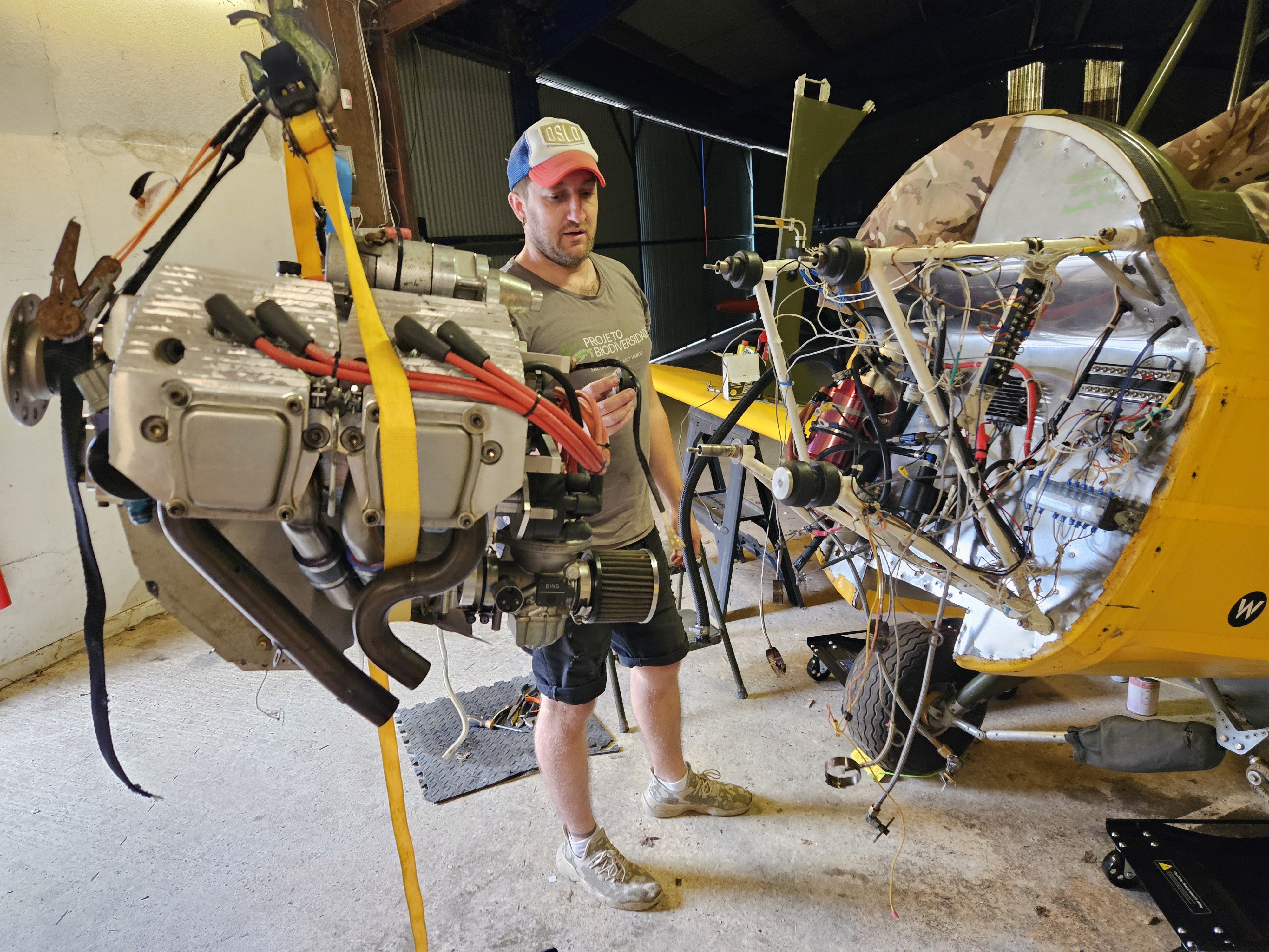
The engine progress has been super slow..
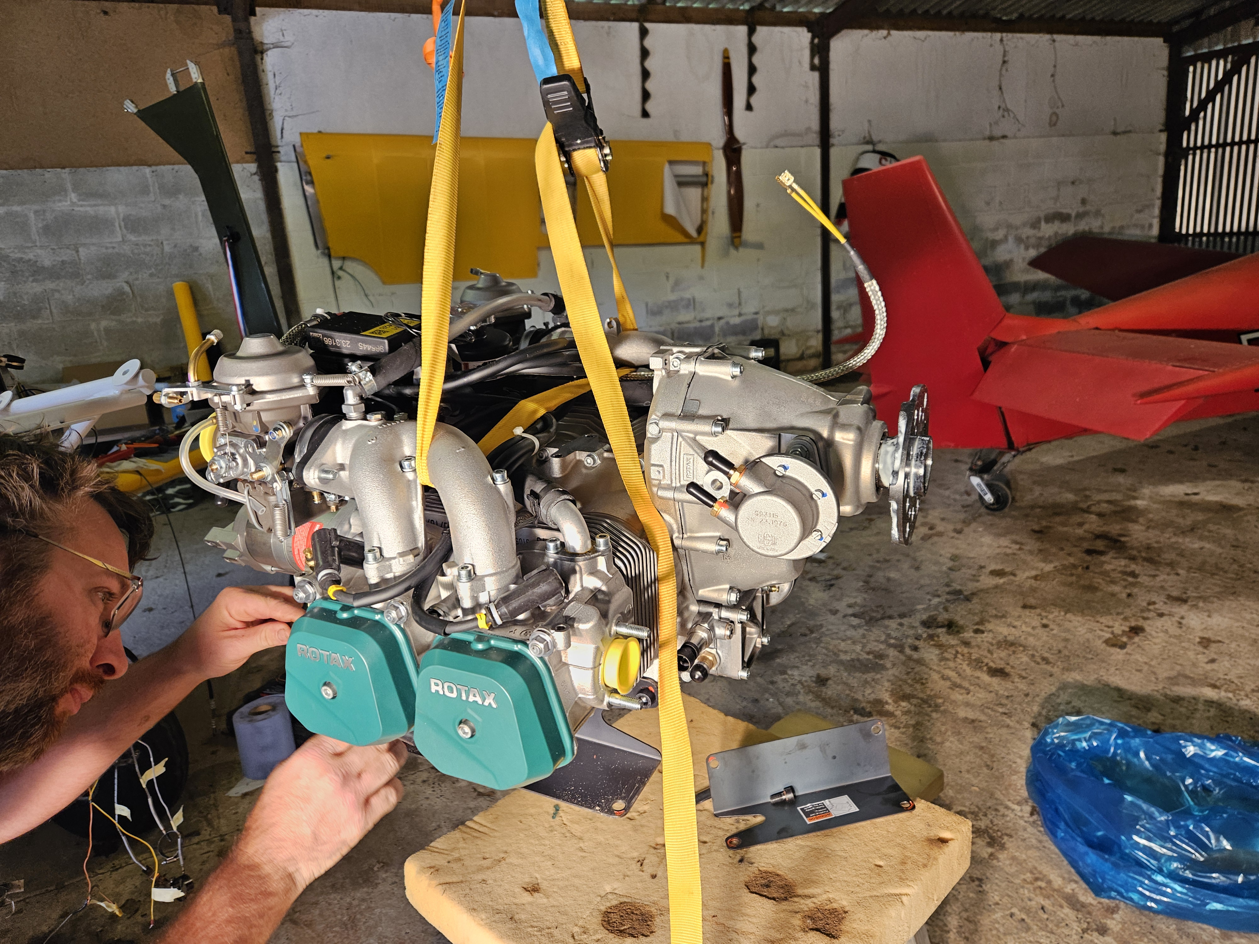
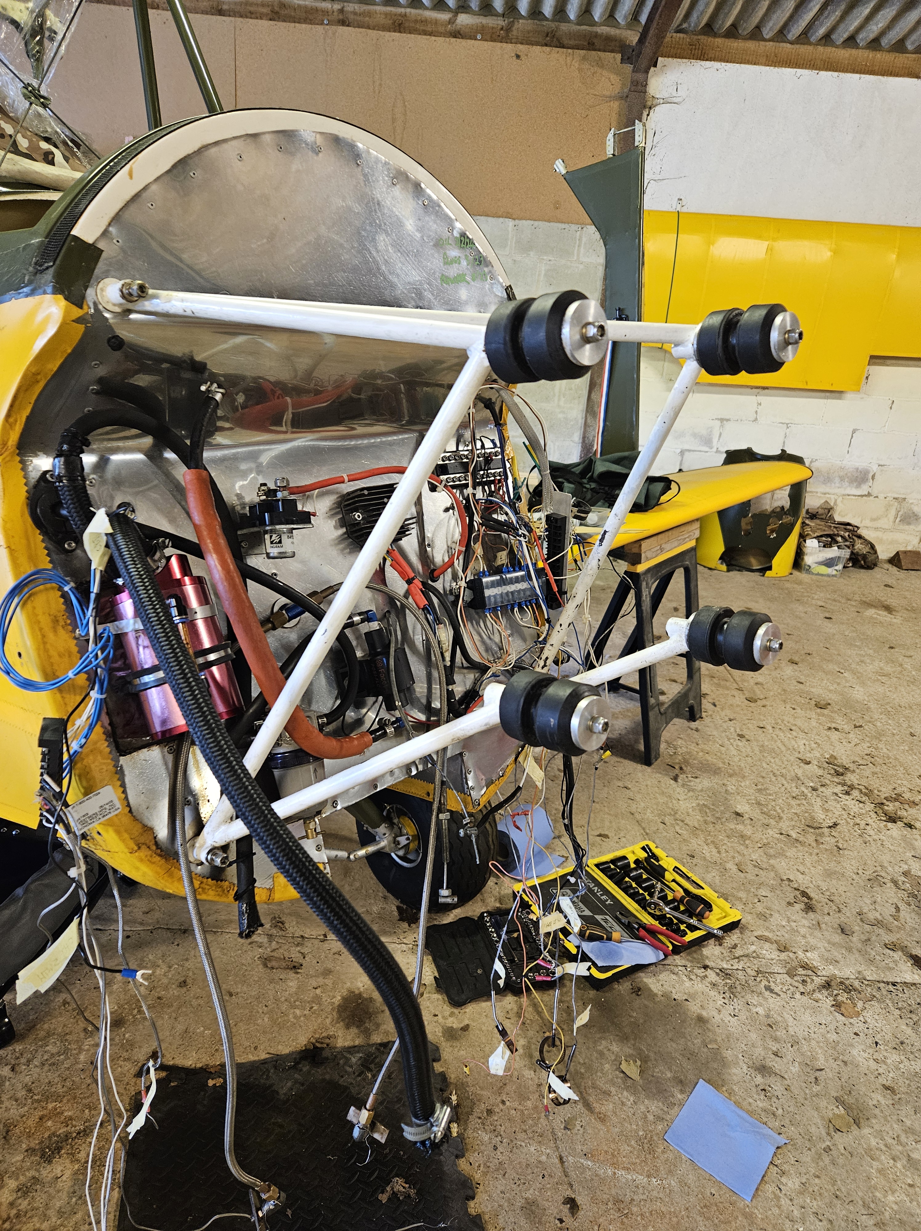
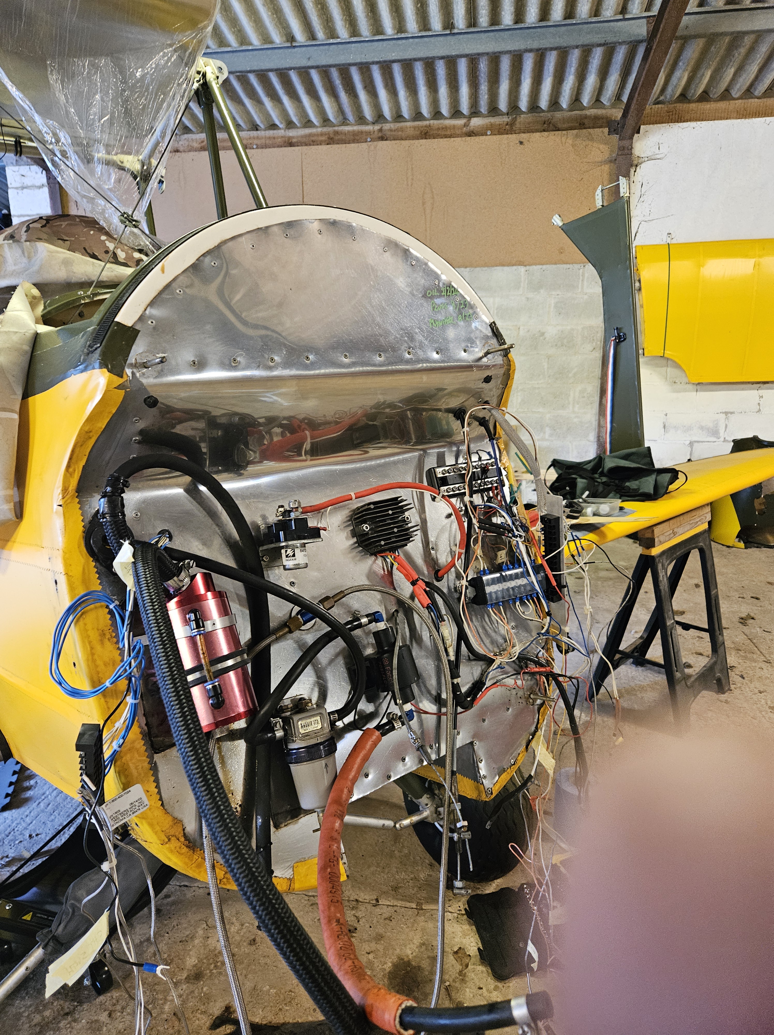
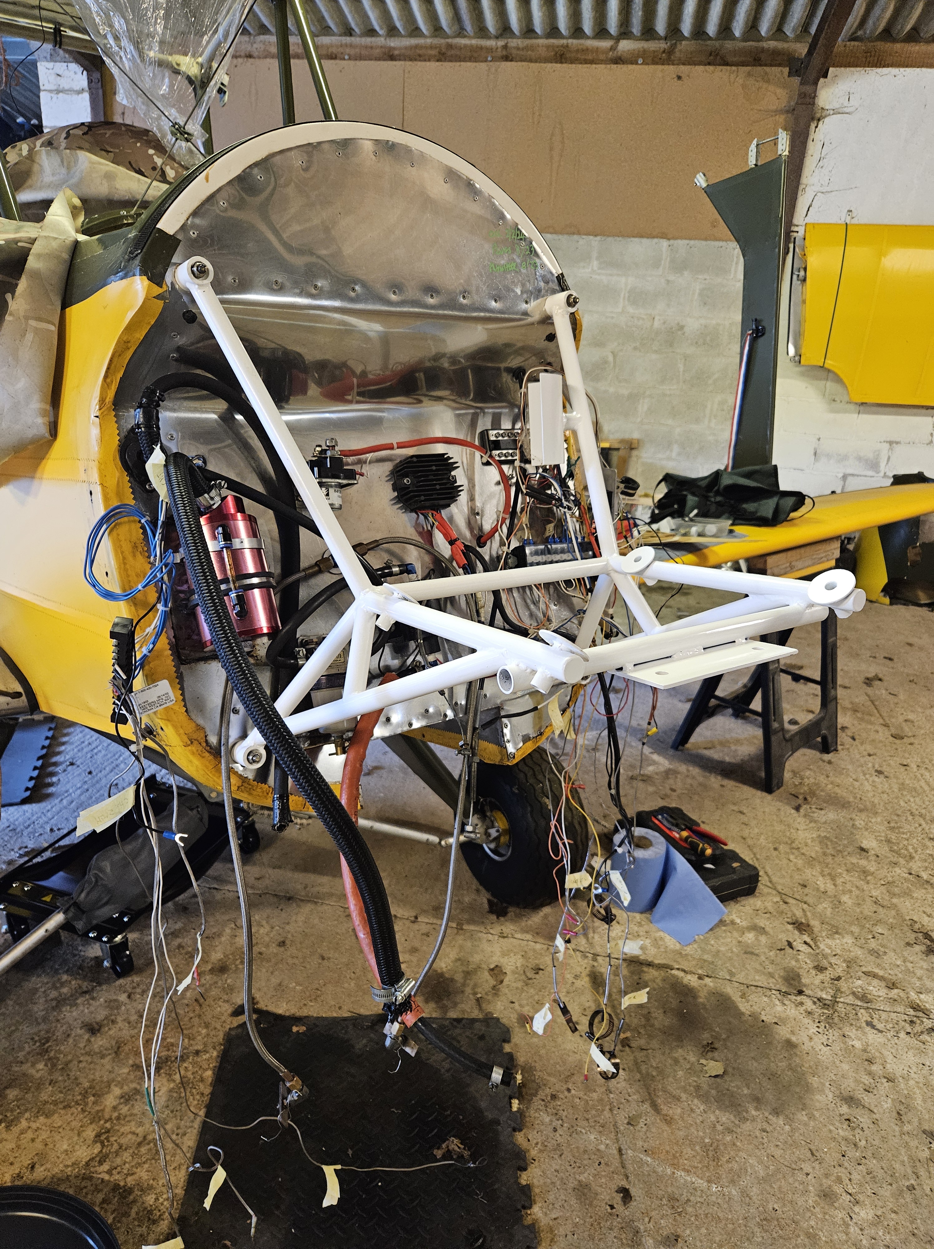
Having bought the mice shiny new Rotax 912ULS i thought it would be a hop, skip and jump to getting her in and ground run…I was warned….
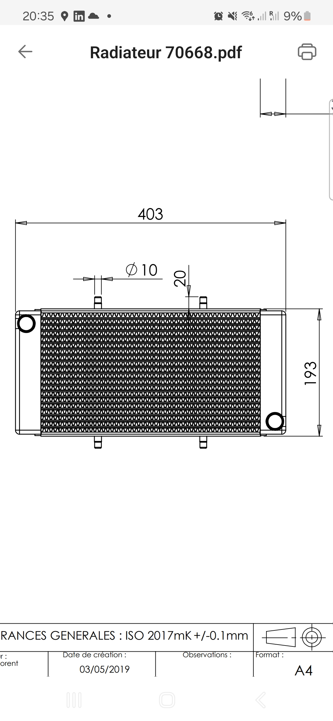
It turns out that sourcing something sime.like the water cooled radiator (something the Jabiru never had – being only Air and oil cooled) is a minefield !
Size, shape and properties are just the simple things ! Relatively .. the next main thing is actually sourcing one ..
You would think that would be easy but no … after much hunting around AND picking the brains of some French friends across the channel I have finally located a source … turns out their online system has to take your order and pre process it to calculate the (proposed) 25 Euro delivery fee… but … it doesn’t actually calculate it online. Their (intersting) way around this conundrum is to show a charge that is so off the scale .. it’s obvious that it hasn’t been calculated …
.. for the circa 300 Euro water radiator .. the delivery charge (pre estimate) ..is …not 100, not 1,000, not 10,000, not 100,000 … oh its quicker to say …
Euro 10,000,000 !!!!
Yes, I’m currently awaiting a (slight) decrease in my estimated invoice of 10,000,300 euros … I’ll let you know
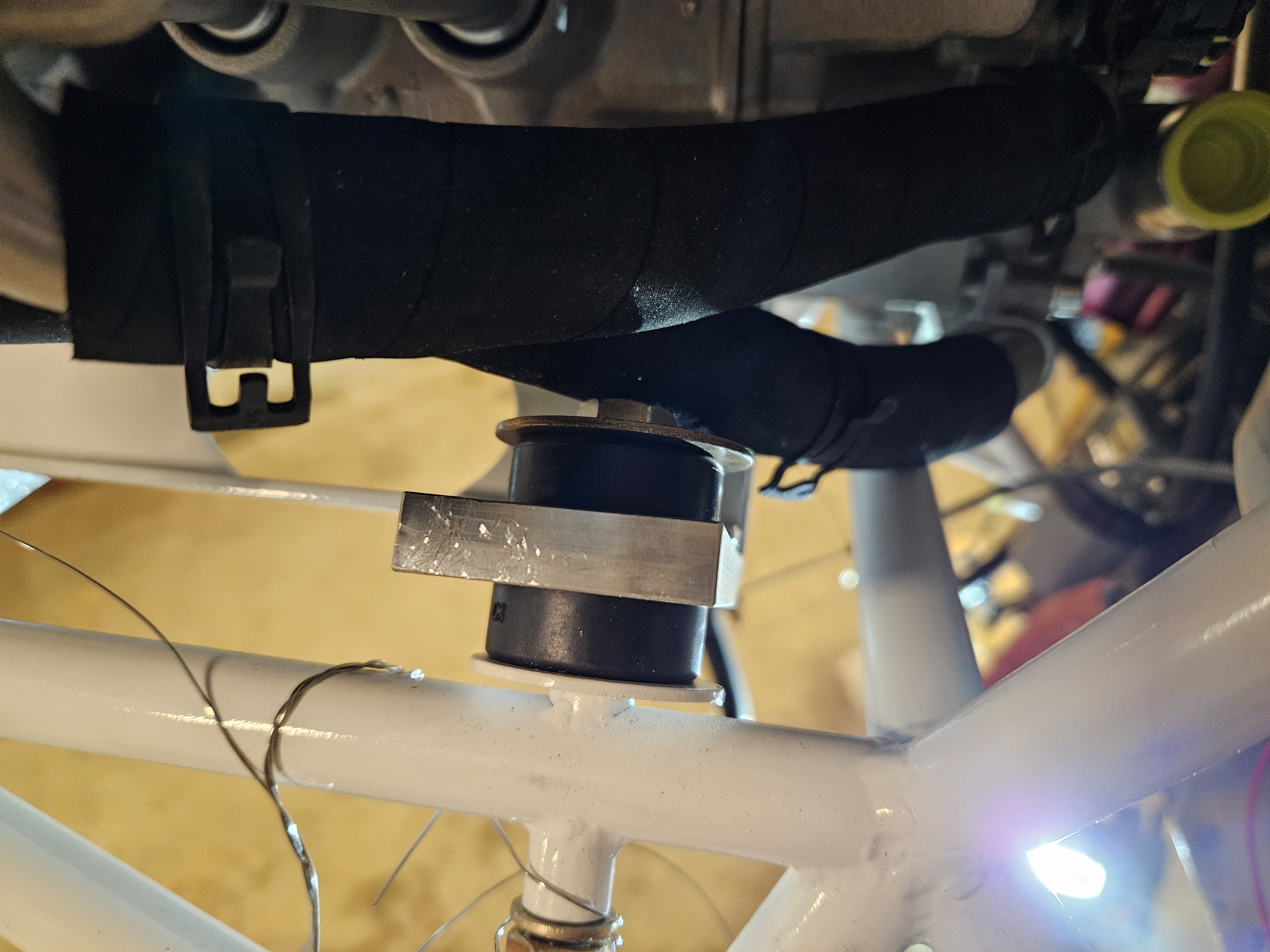
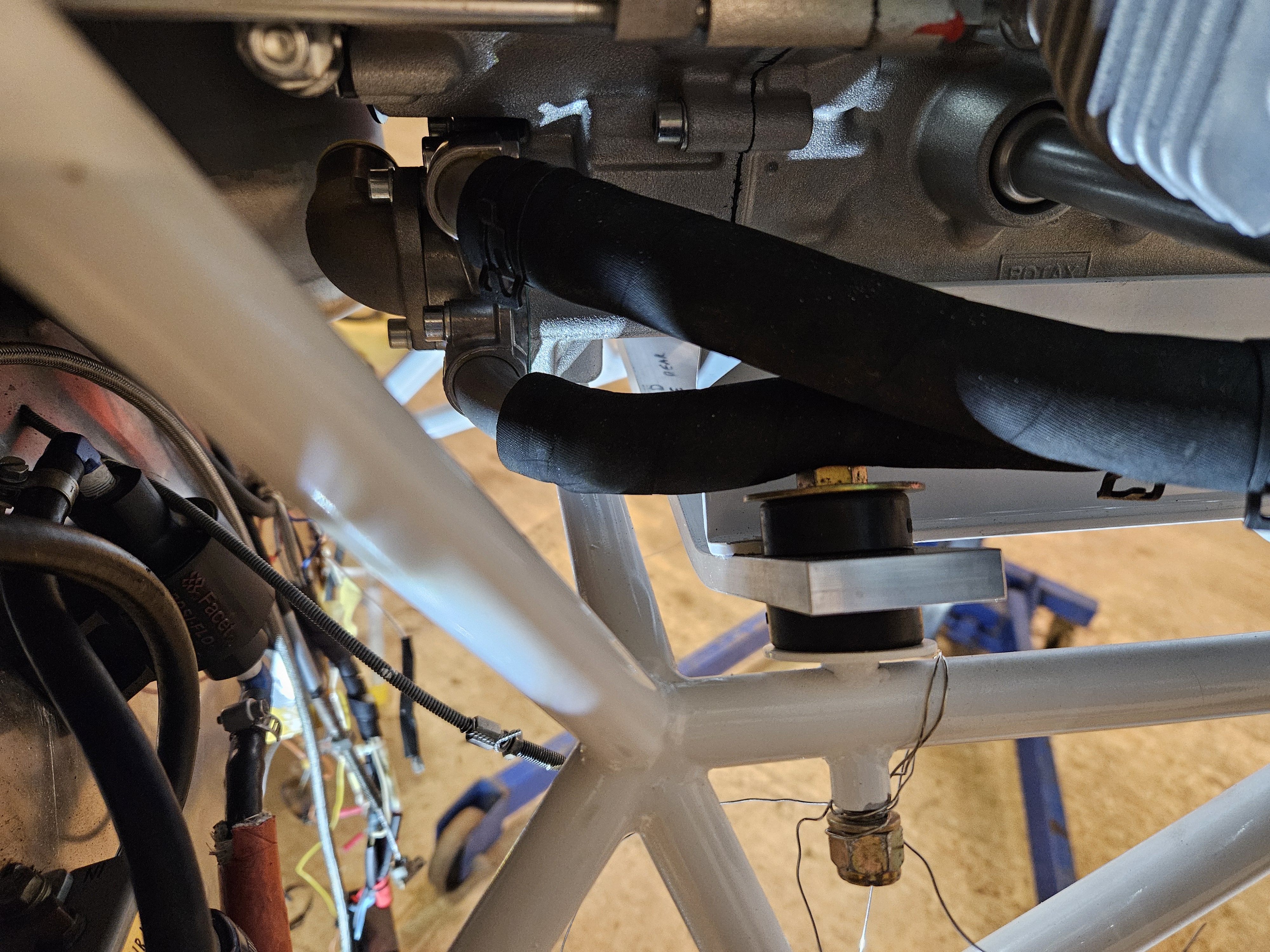
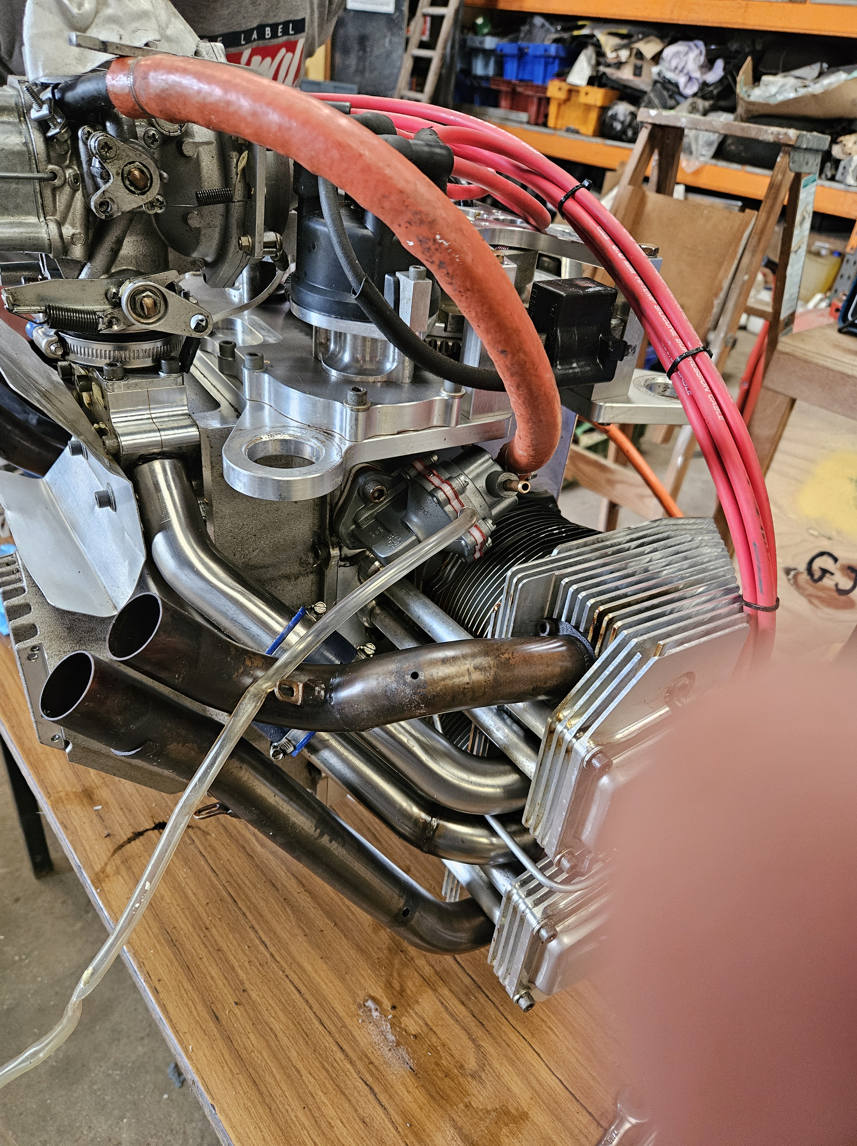
The exhaust had been a similar and arduous dilemma until I located a Czech company who provided and shipped the kit relatively painlessly.
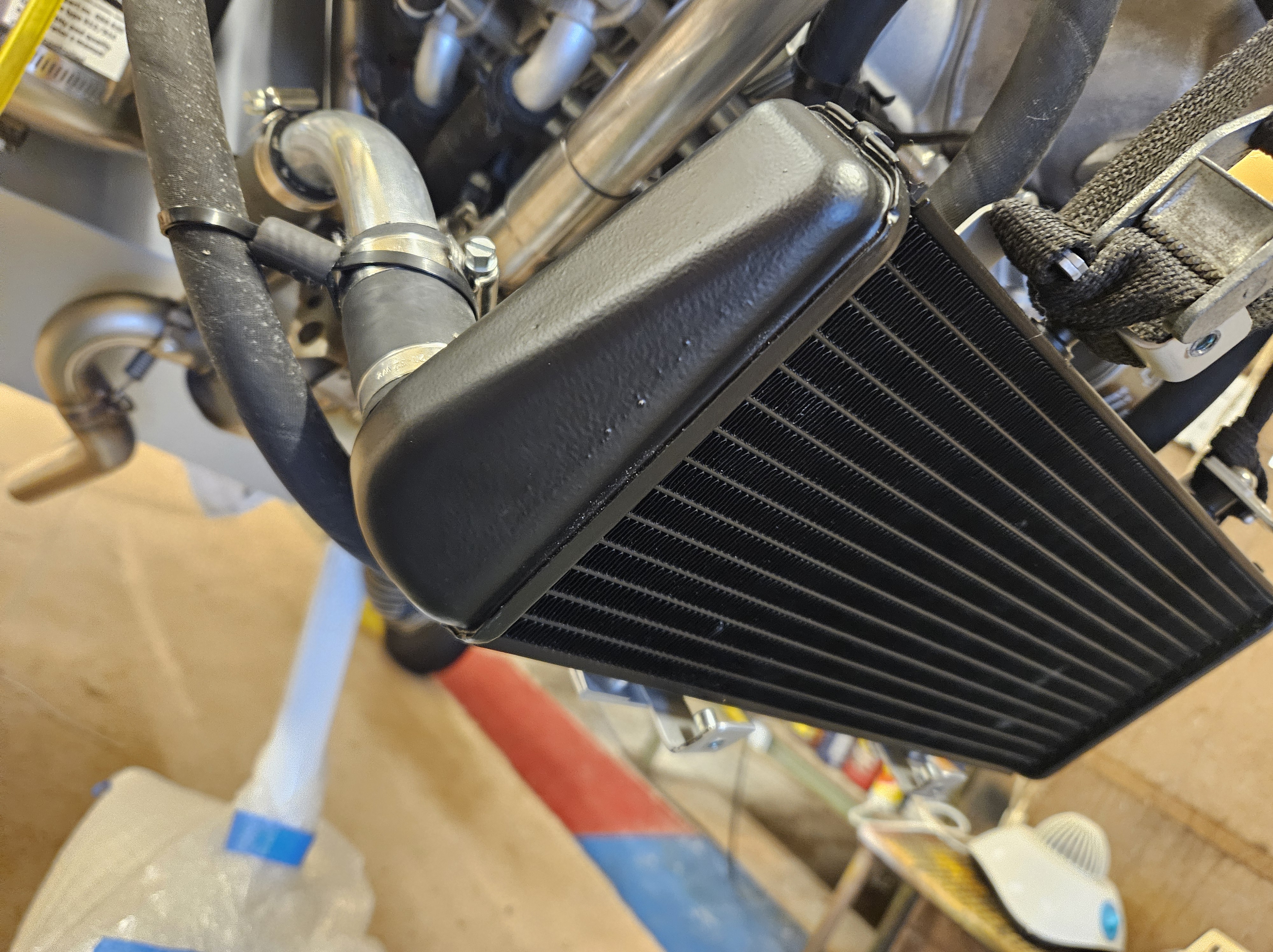
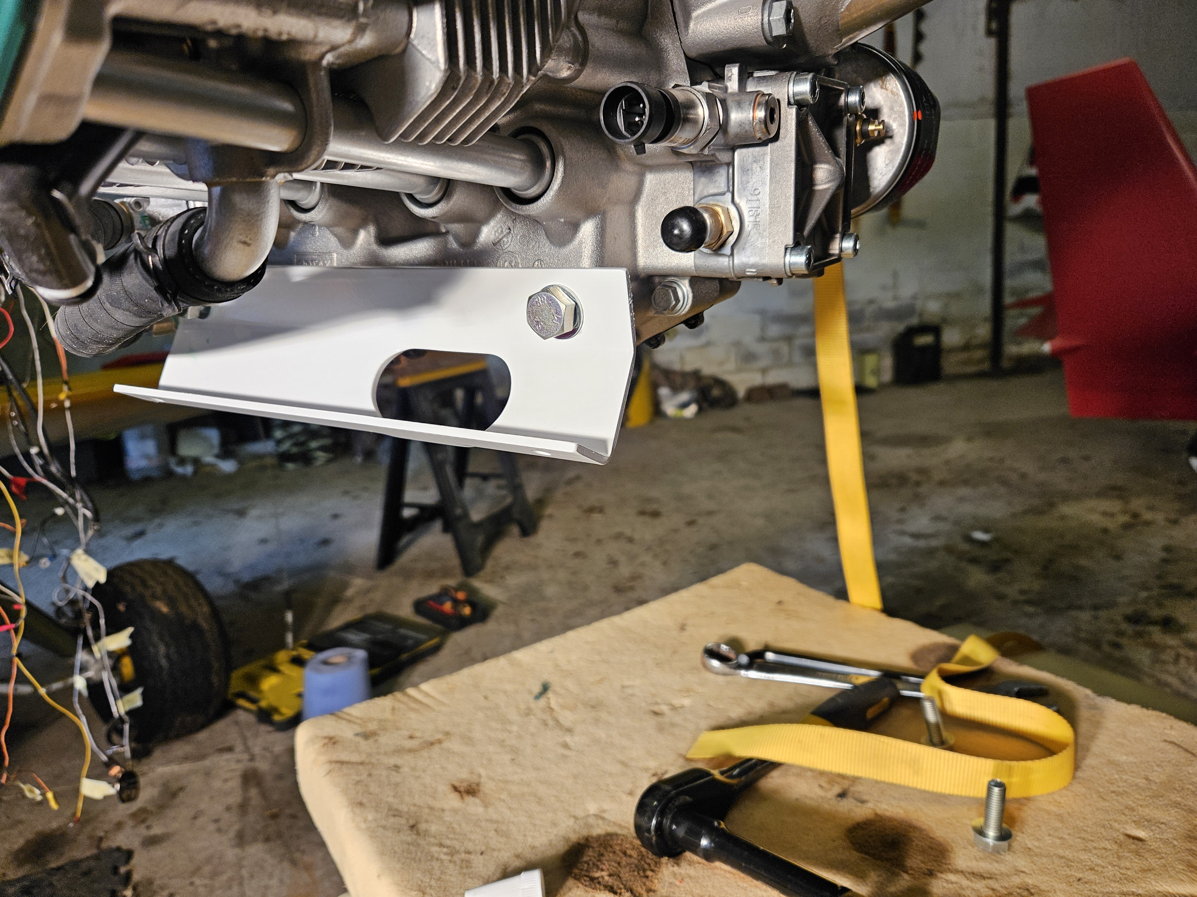
The oil radiator I’ve managed to source in the UK along with some throttle and choke cables and await these with my Horis instrument upgrade. The oil rad will not be mounted front and centre in the cowl as the fairly large radiator will make for some wide cowl cheeks .. so it’s going to be underslung at an angle .. say 30′ to the airflow but perhaps have a ram air duct to drive Air through .. the French have tried this and it seems successful on the relatively slow moving Ranger.
Once this ‘Eurovision’ of engine parts comes together it’s off to the local specialist for pipe shaping and bracket making …
Then we can start to think propellor and cowl… wonder which continent next 🤔