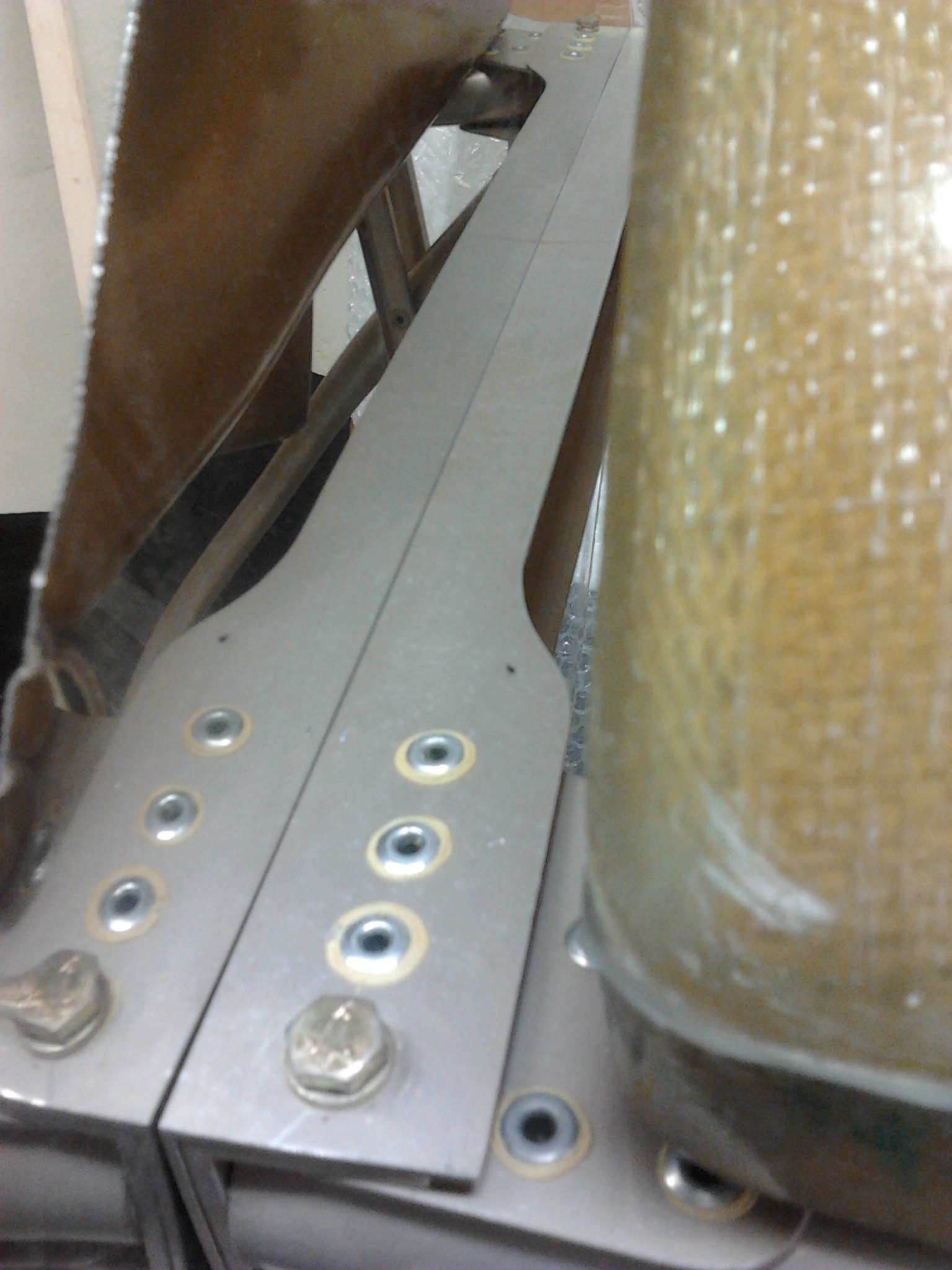
Control Sticks

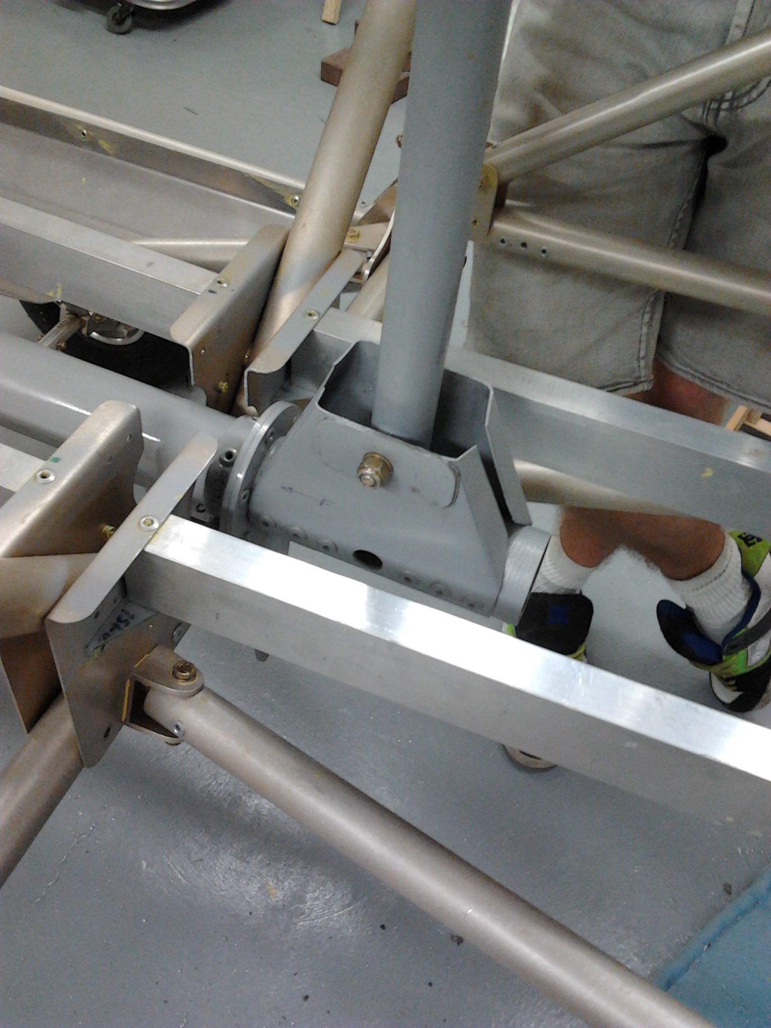
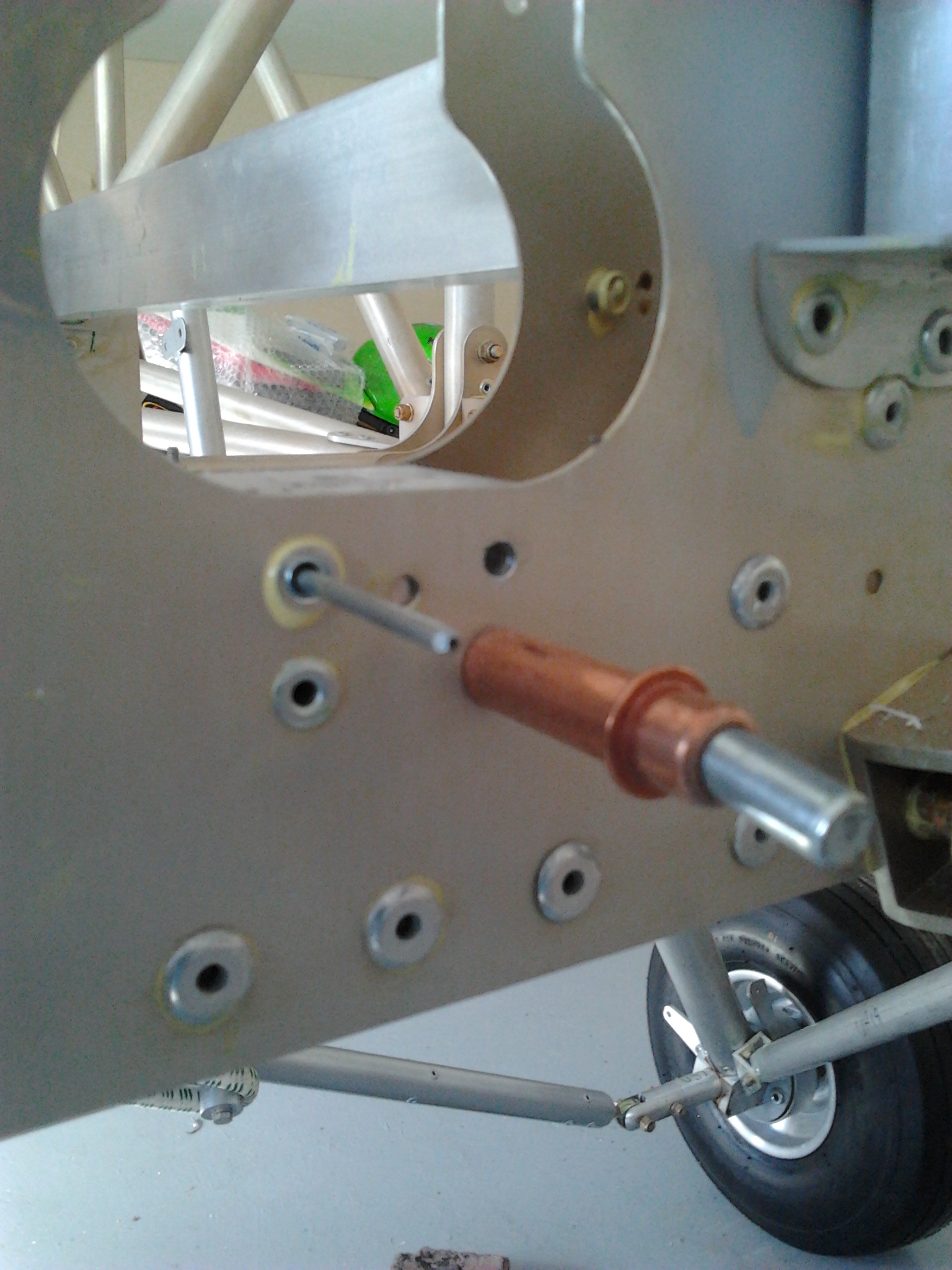
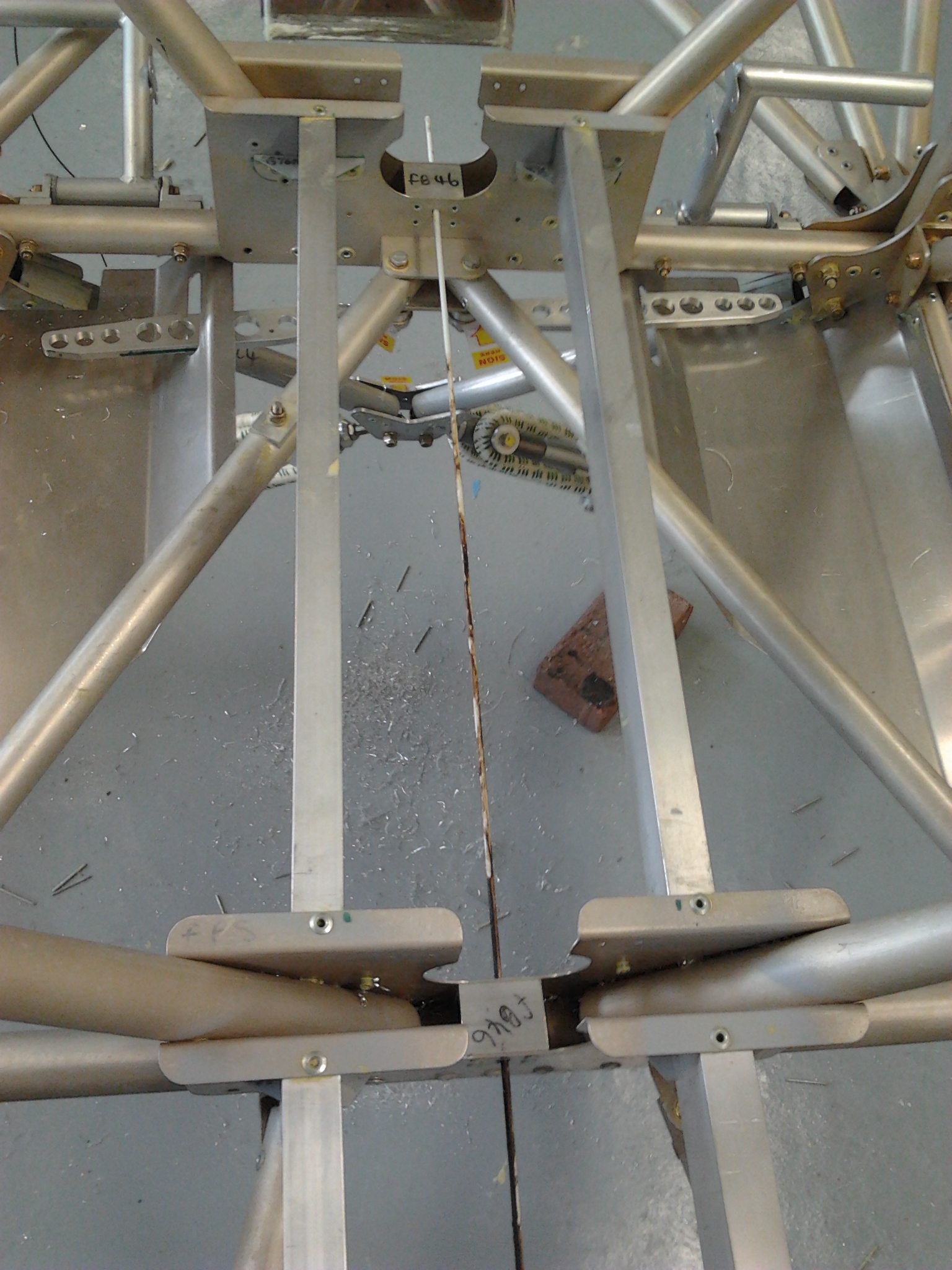
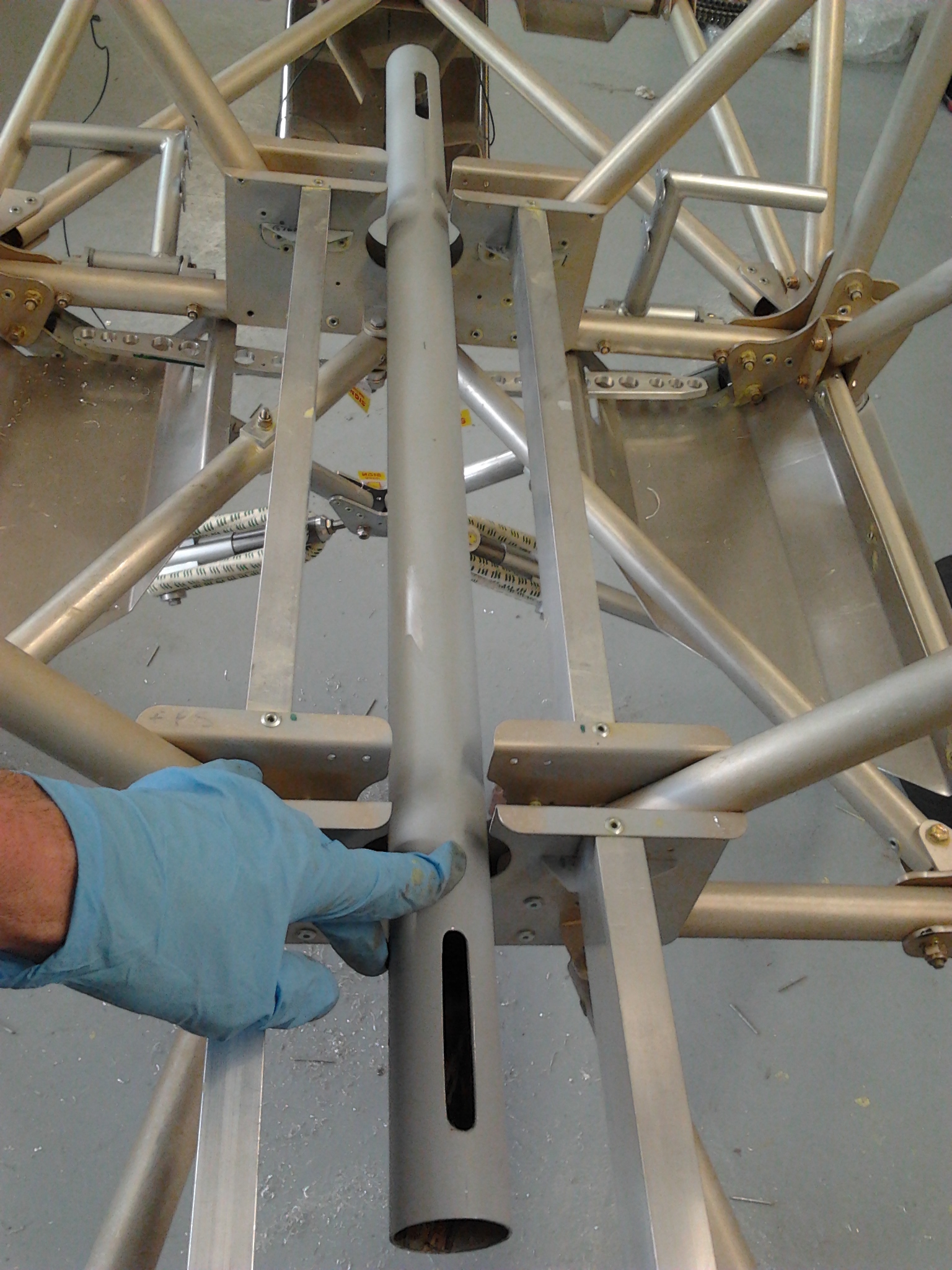
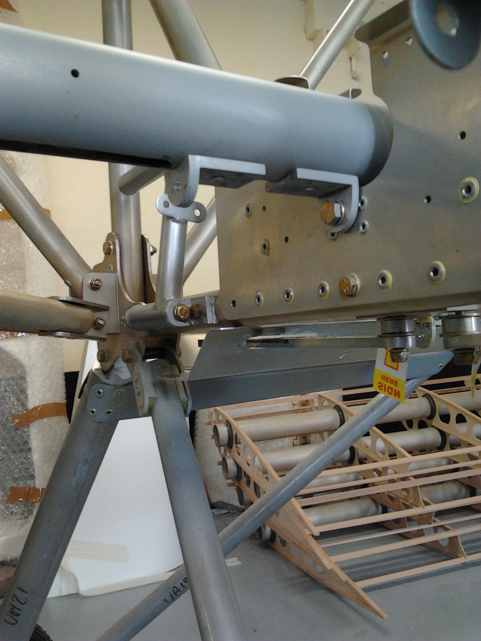
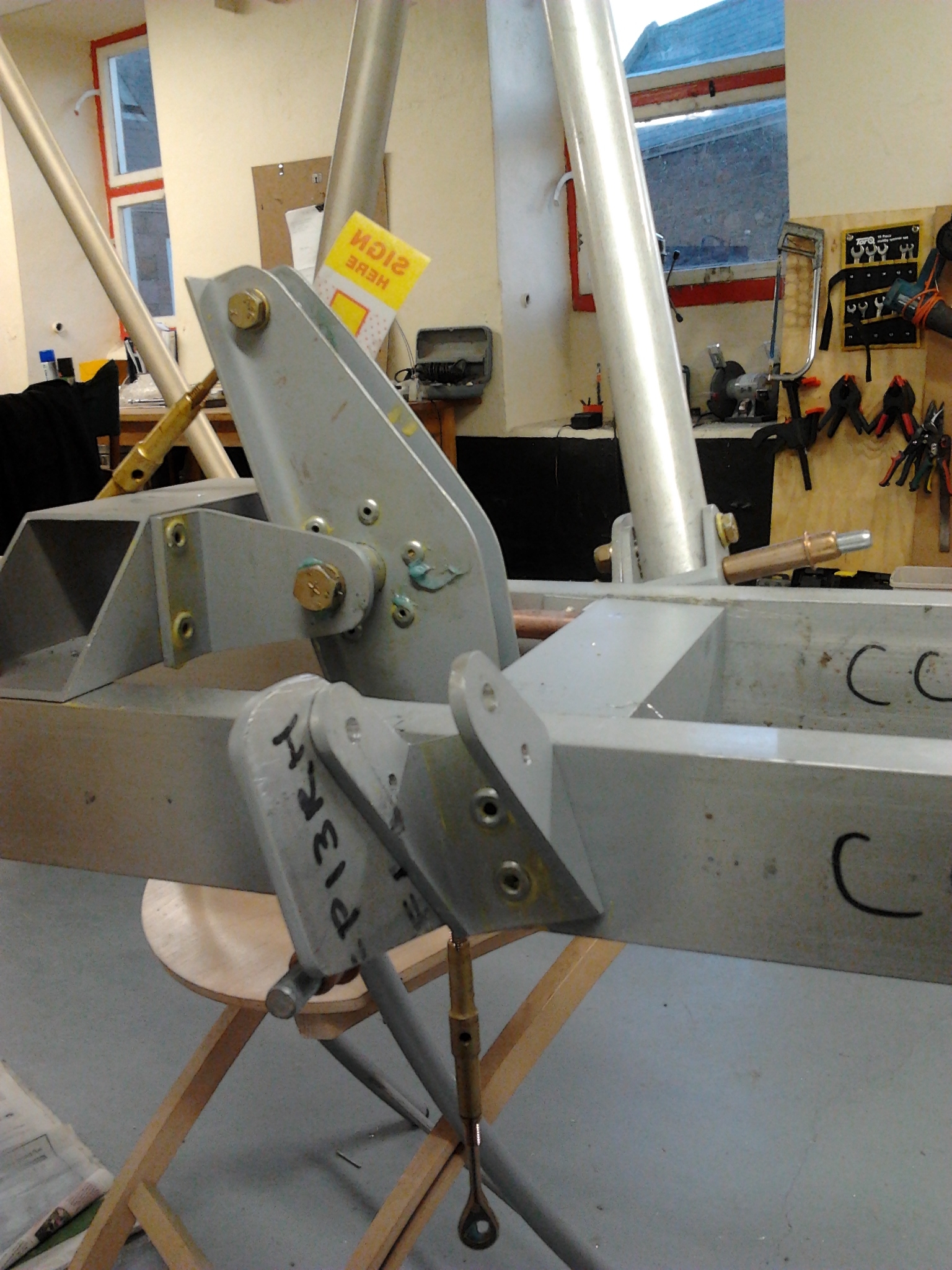
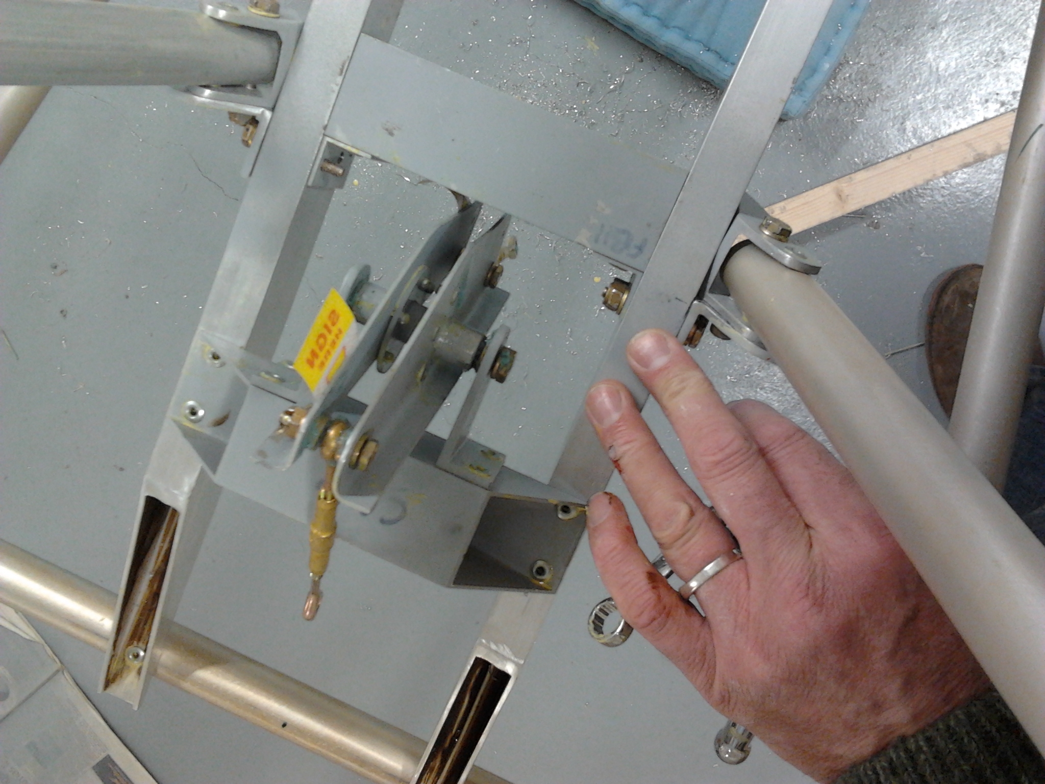
Once the Torque rod is in place you can complete the shaping of the Control sticks. These mount inside metal sided shrouds and run in bushes. The spades of the control rods run in the central slots you have shaped in the torque rod tube.
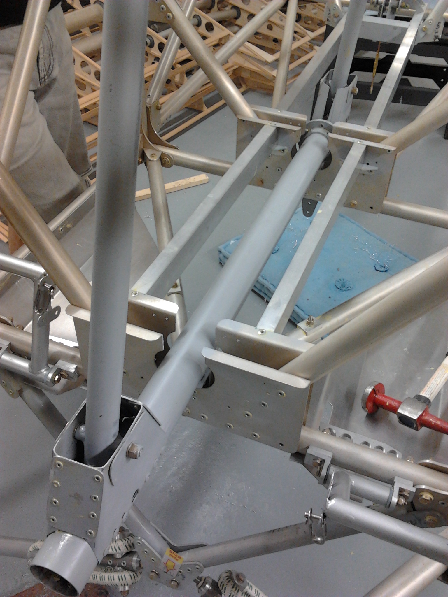
2 joysticks in place

You need to have a widened hole in the side of the torque tube aligned with a similar one in the shroud so that you can retrospectively fit the internal elevator control rod clevis pin.

I found the front elevator space welding slightly proud and catches slightly on full forward and full aft movements. Small filing – re etch prime and its fine.

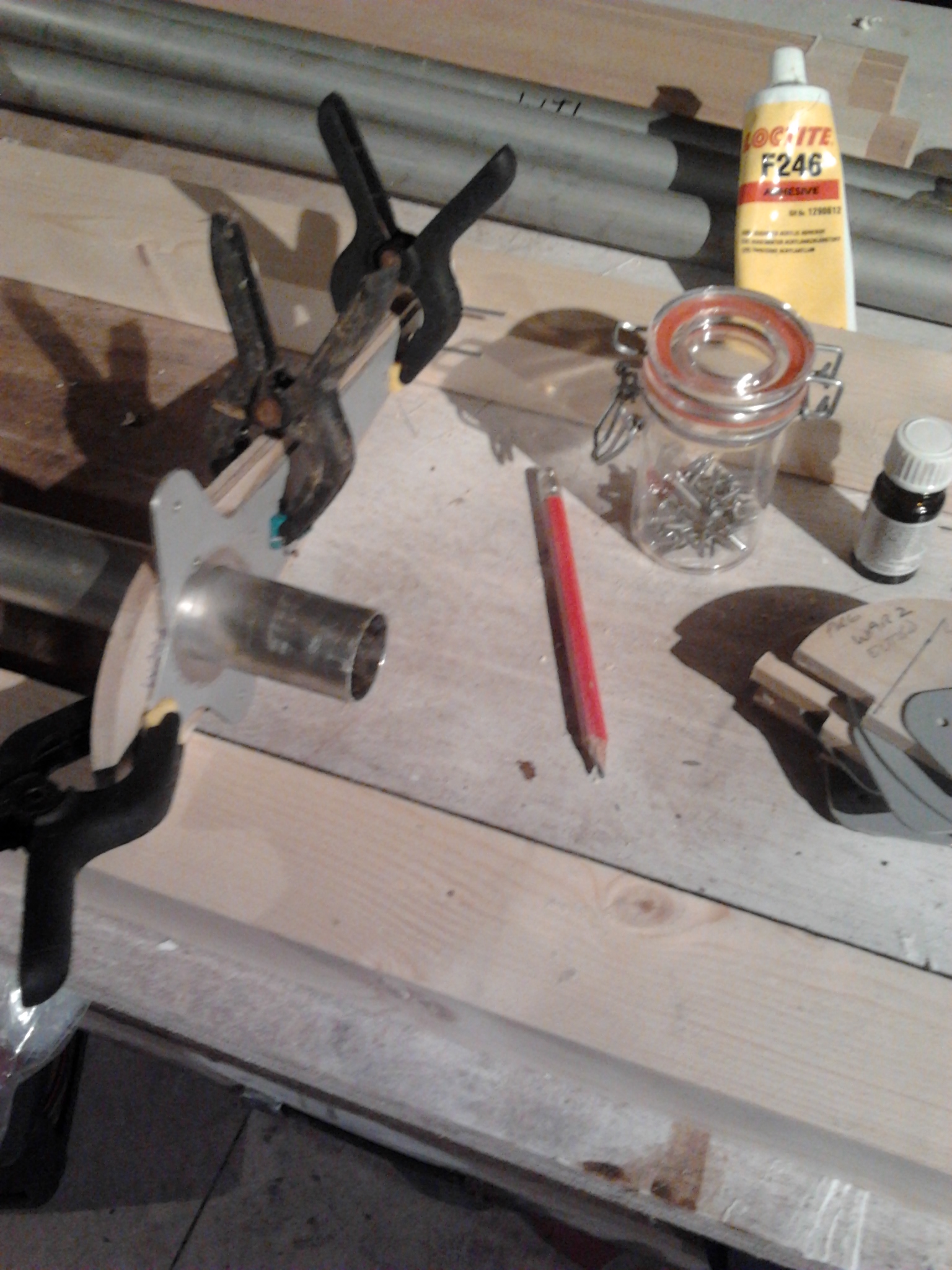
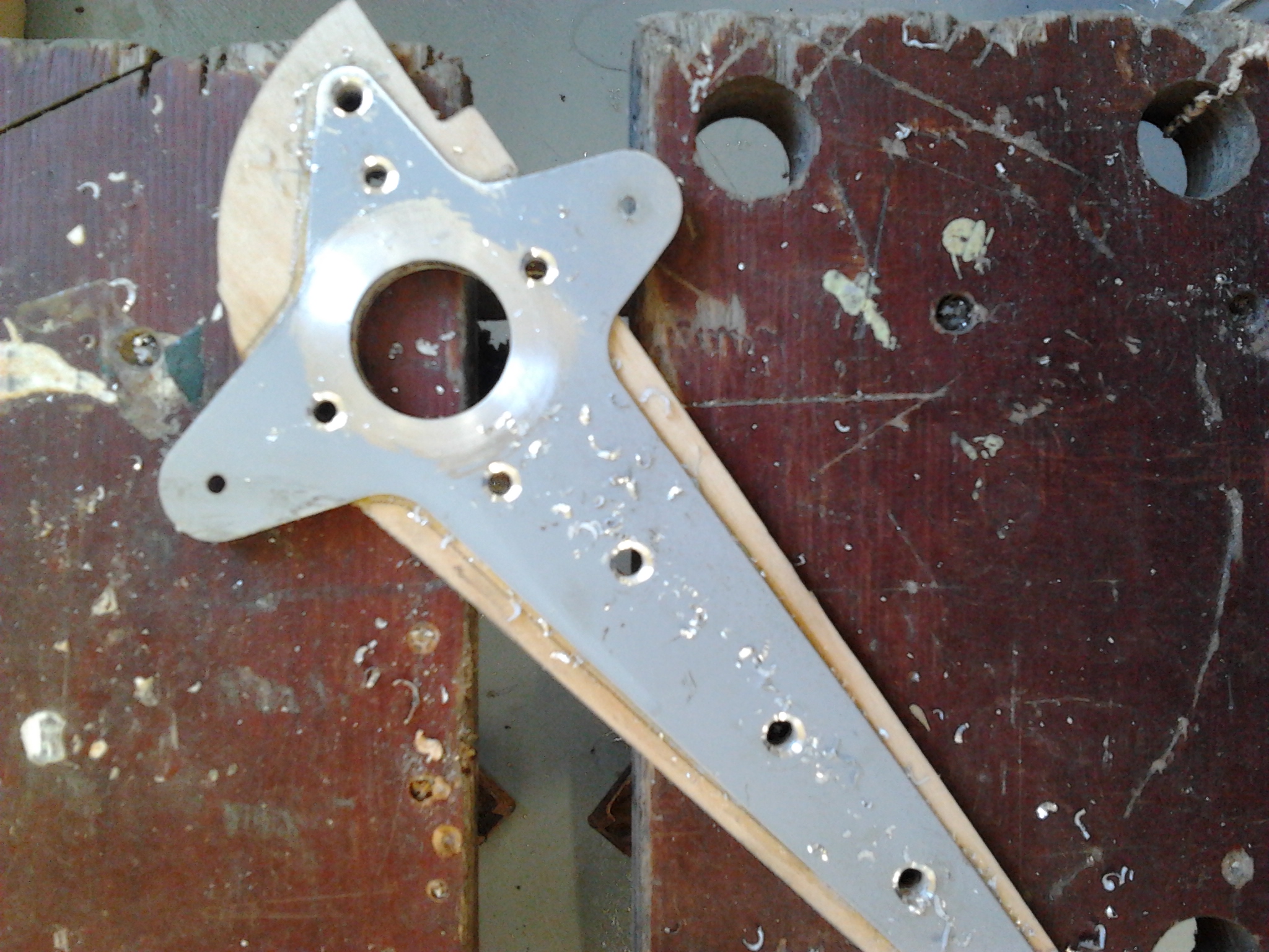
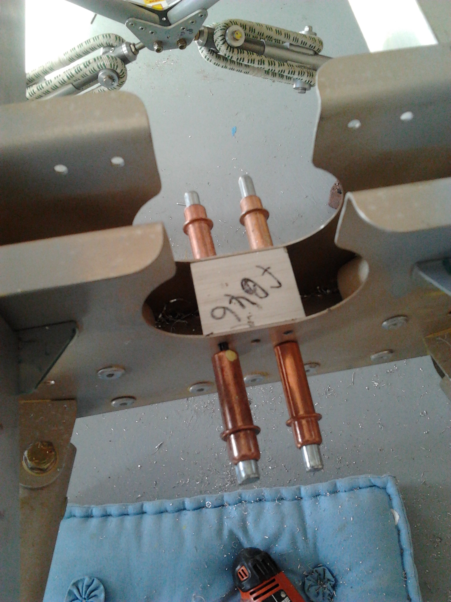
Careful sequencing to align the aileron collar and control horn and then fit pilot joystick.. good experience for Sam to have a go at nickel rivets …
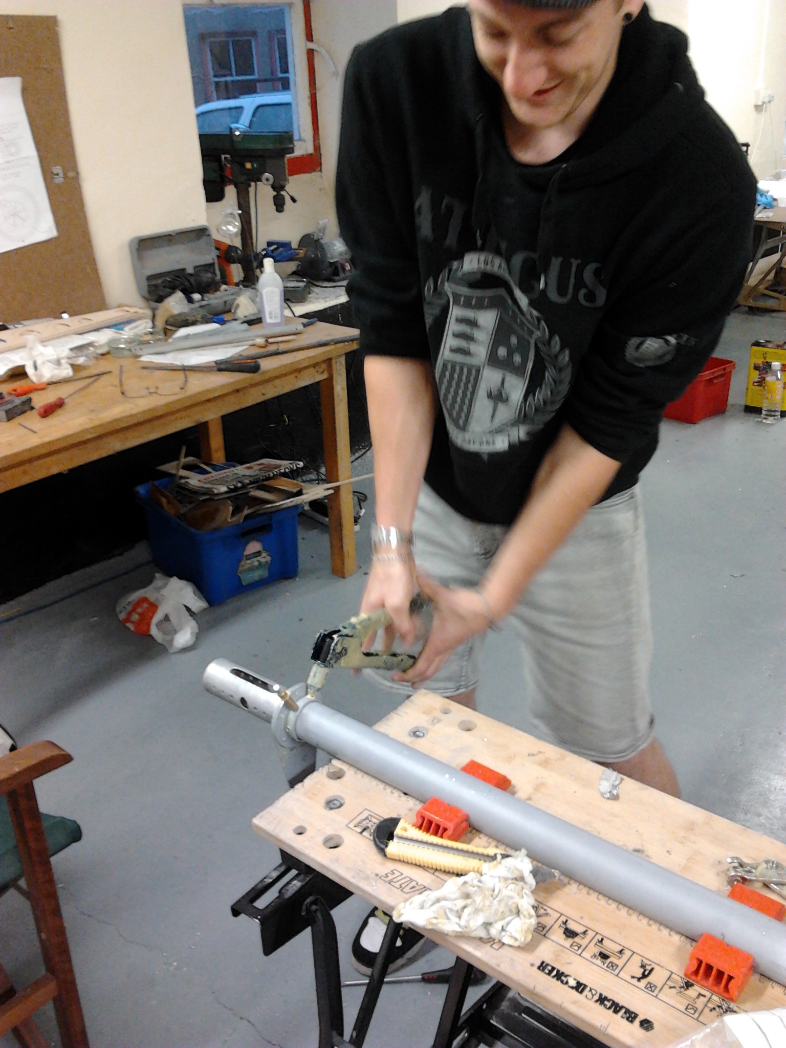
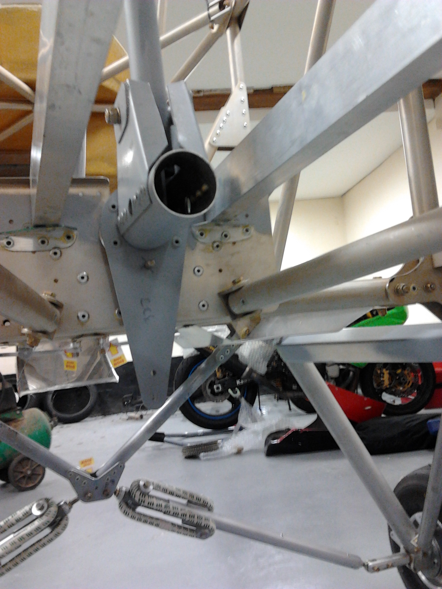
sam riveting horn aileron horn lower

aileon horn top view

Aileron Rib Peparation

Aileron ribs have metal doublers bonded

Aileron rib doublers

You have to be carfeul to make the correct Left and Right hand units. .. so doublers are on one side or the other depending if it is a LEFT or a RIGHT aileron … also need to check if its an UPPER or a LOWER aileron so that the pick up points are in the right direction !

TLAC provide a picture page to ‘pre test’ you on which aileron rib is which.

I found each rib needed to be sanded so that it could get onto the aileron spar.. again .. not too much off to keep it as a stiff fit.

Aileron rib rivets

This work is not being carried out at the barn but in my garage roof at home so I can nip out and do the odd hour here and there and its warmer than the barn so better for curing glue and ultimately fibreglass.

Torque rod control

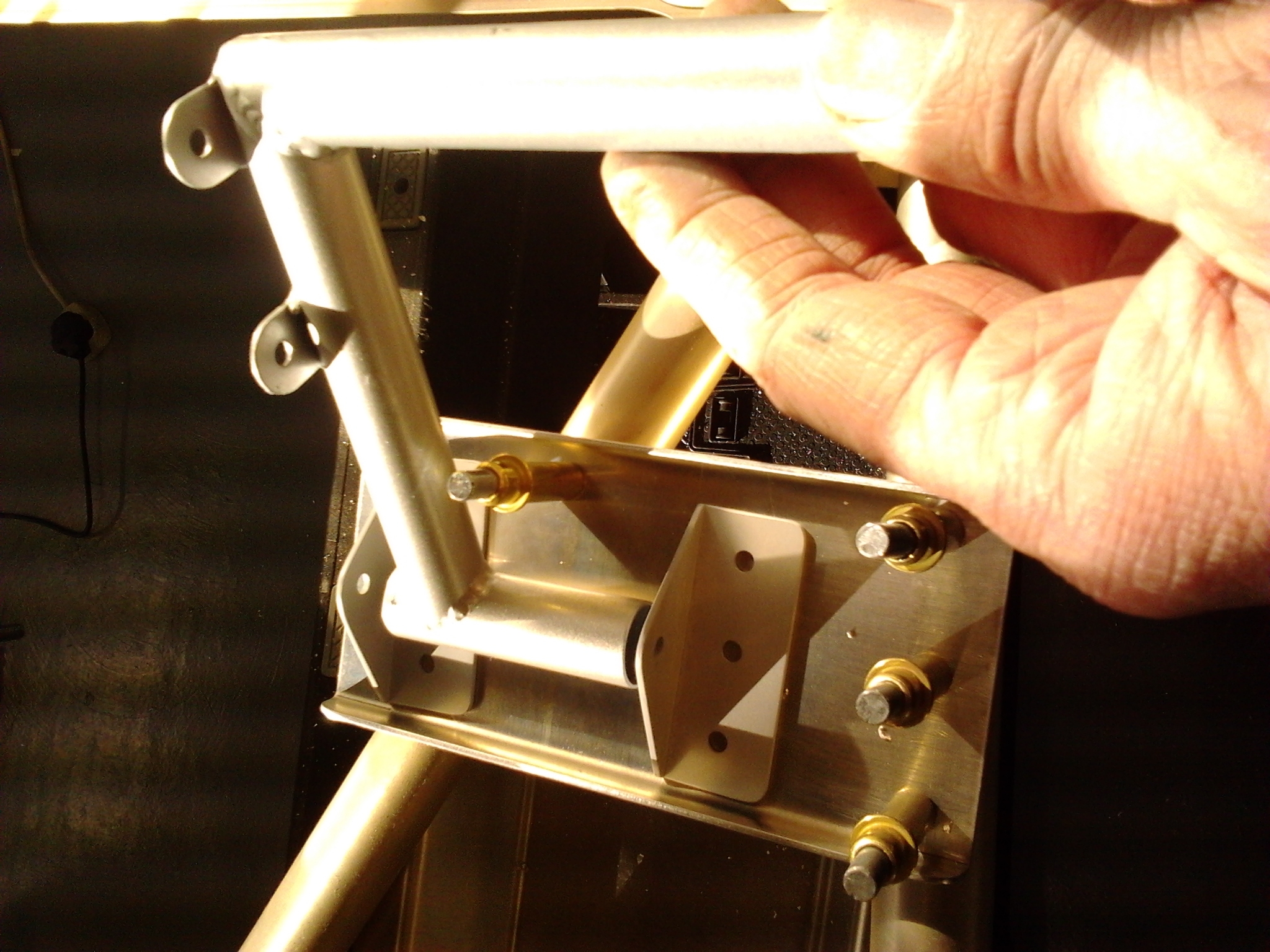
Fit the support centre bracket between main plates. This has doubler plates that have been pre glued to the inside faces.

Torq control mount position  Torq control mount bracket

Check alignment using fixed rigid between holes .. this is key so that the aileron movement of the torque rod is smooth axially.

Torq align check

Fit Torque tube and ensure ease of aileron movement and no end float

Torq tube in position

Confirm hinge washers

Torq hinge lower

I had a slight problem with one of the brackets moving fractionally when I came to remove the temporary rivets and pre glue them onto the torque rod. The plan guidance says you may need to slightly widen a hole to get smooth movement and a minute amount of filing of the centre bracket leaves the movement finger light !

Elevator intermediate horn

This is shaped and etched and spaced before applying rivet fixing on central spindle.

Intermediate Elevator horn Intermediate elevator horn 2

The intermediate horn sits between the seat rails and is positioned to pickup the ‘tail end’ of the elevator interconnecting rod (yet to be completed) that runs through the centre (internal) of the control torque tube.

Exhaust Duct

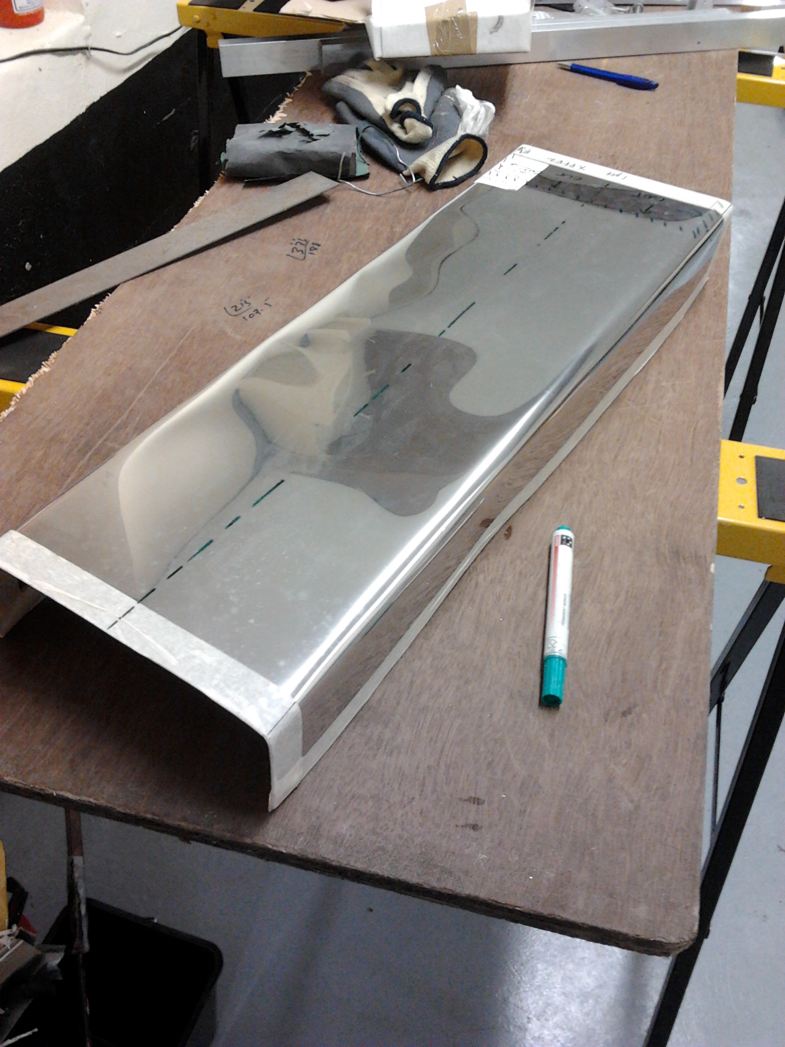
The exhaust duct is shaped from similar guage stainless steel sheeting as the bulkhead. Once shaped it has small flanges folded at the ‘leading edge’ to accept the mounting rivets.

exhaust duct

Seat Rails

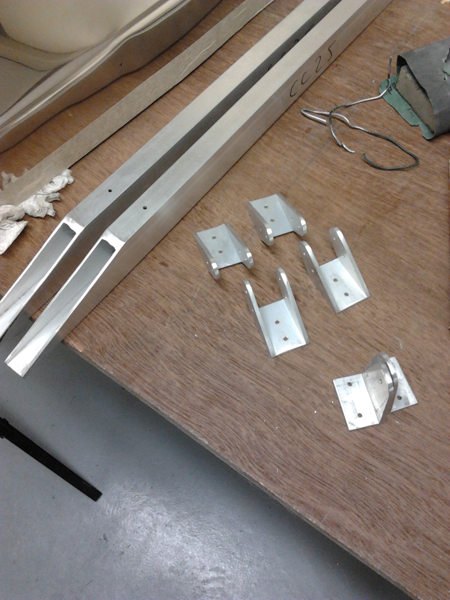
The seat rails fit between various key parts on the body. They require mounting brackets to be profiled to clear rivet heads and the support members profiled to fit.

Seat Brackets

seat rails

Front Rudder Pedals

Rudder pedals are mounted on plates that sit just above the footwells.

The support brackets are drilled and shaped and then etch primed ready

Front pedal plate

Each pedal is bushed and the rivets pick up the main cross beams of the aircraft. The pedals are provided pre welded but need rubbing down, etch priming and then 3 coats of Hammerite.

Left rudder pedal

Bulkhead

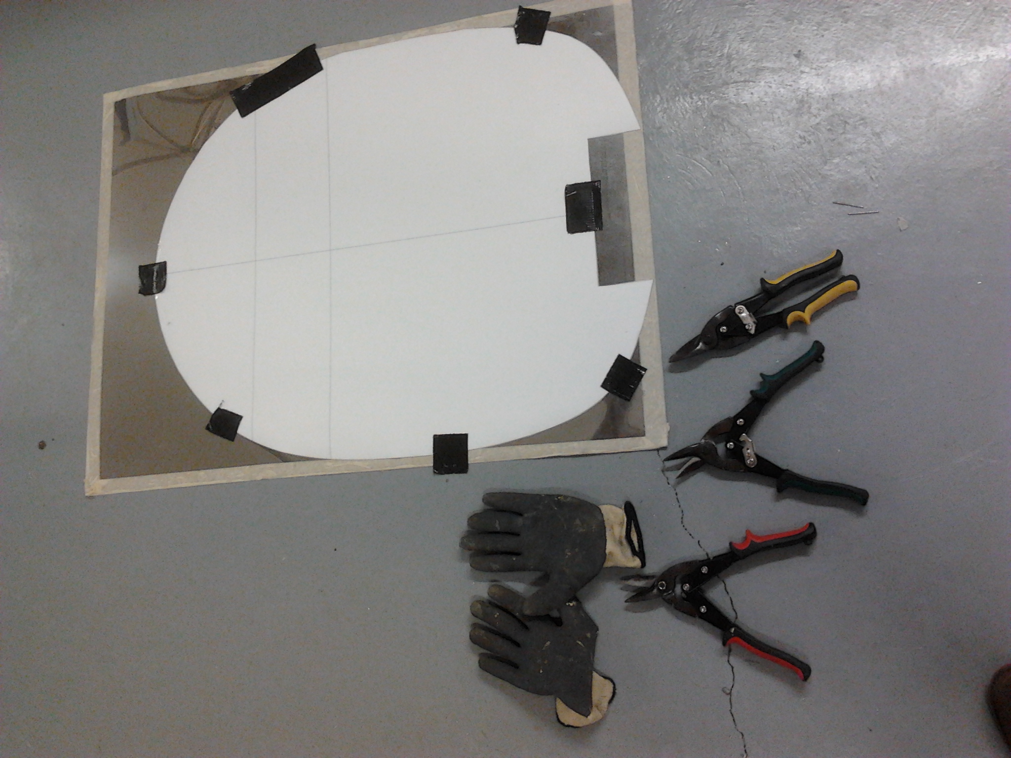
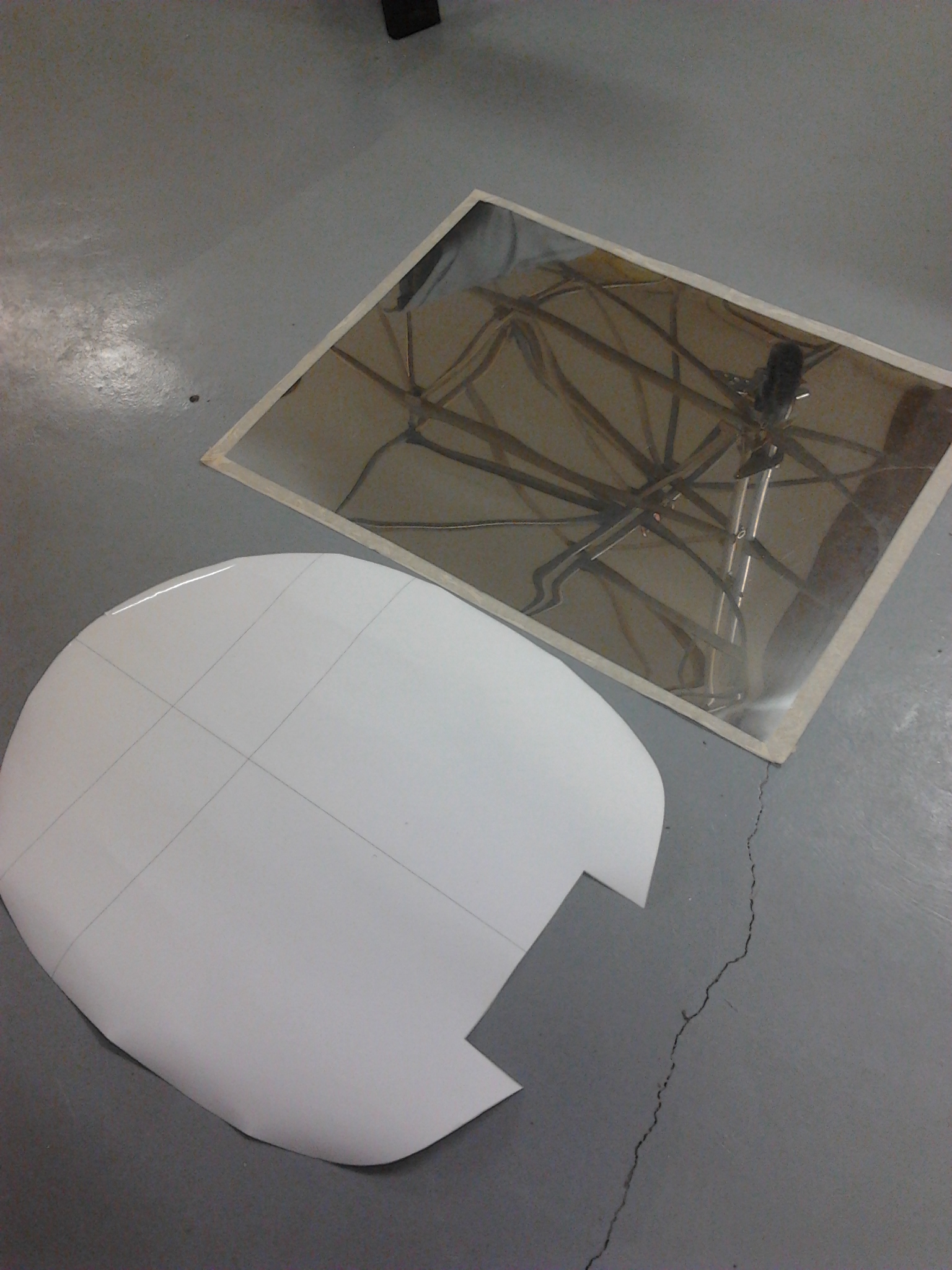
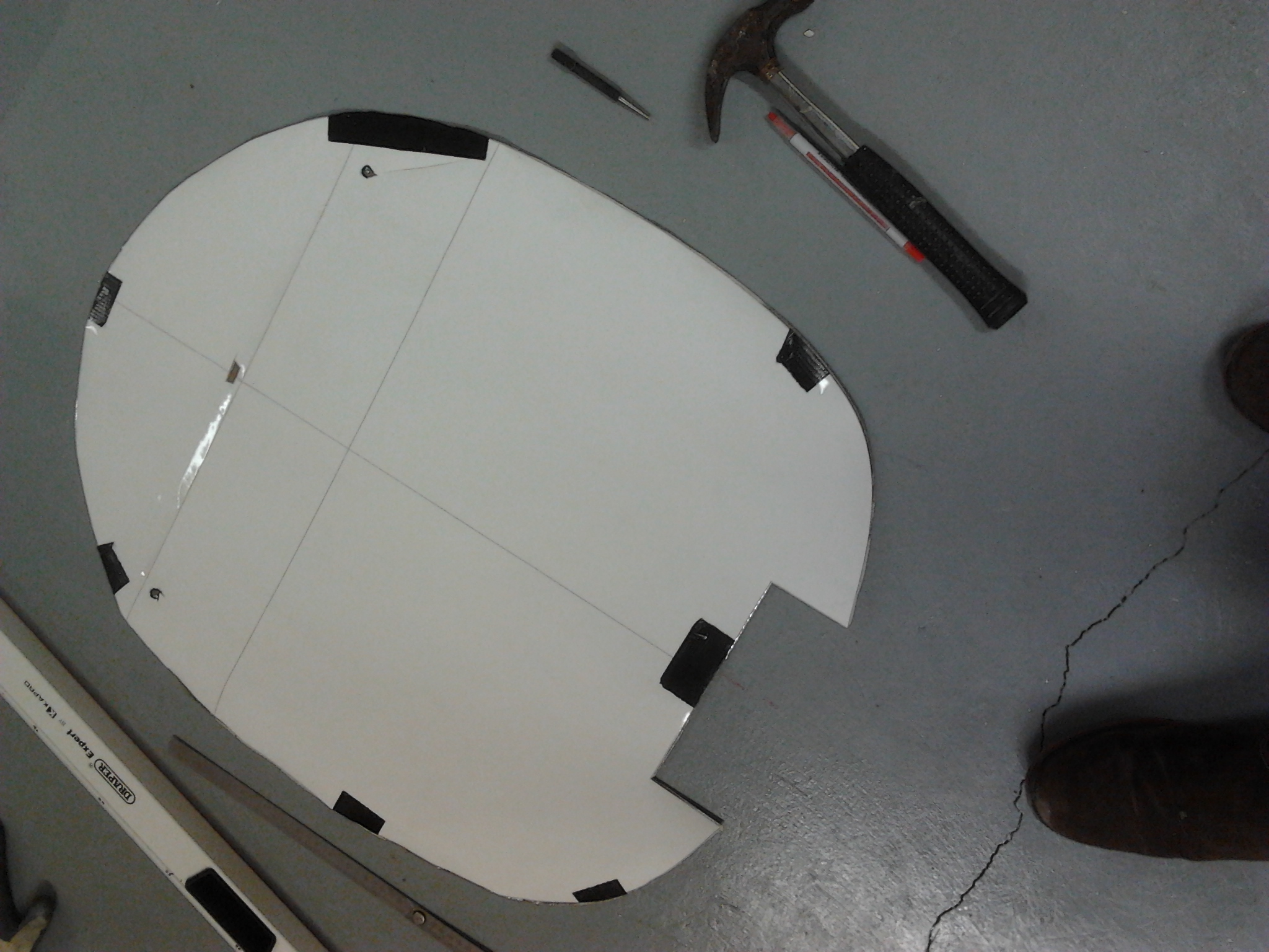
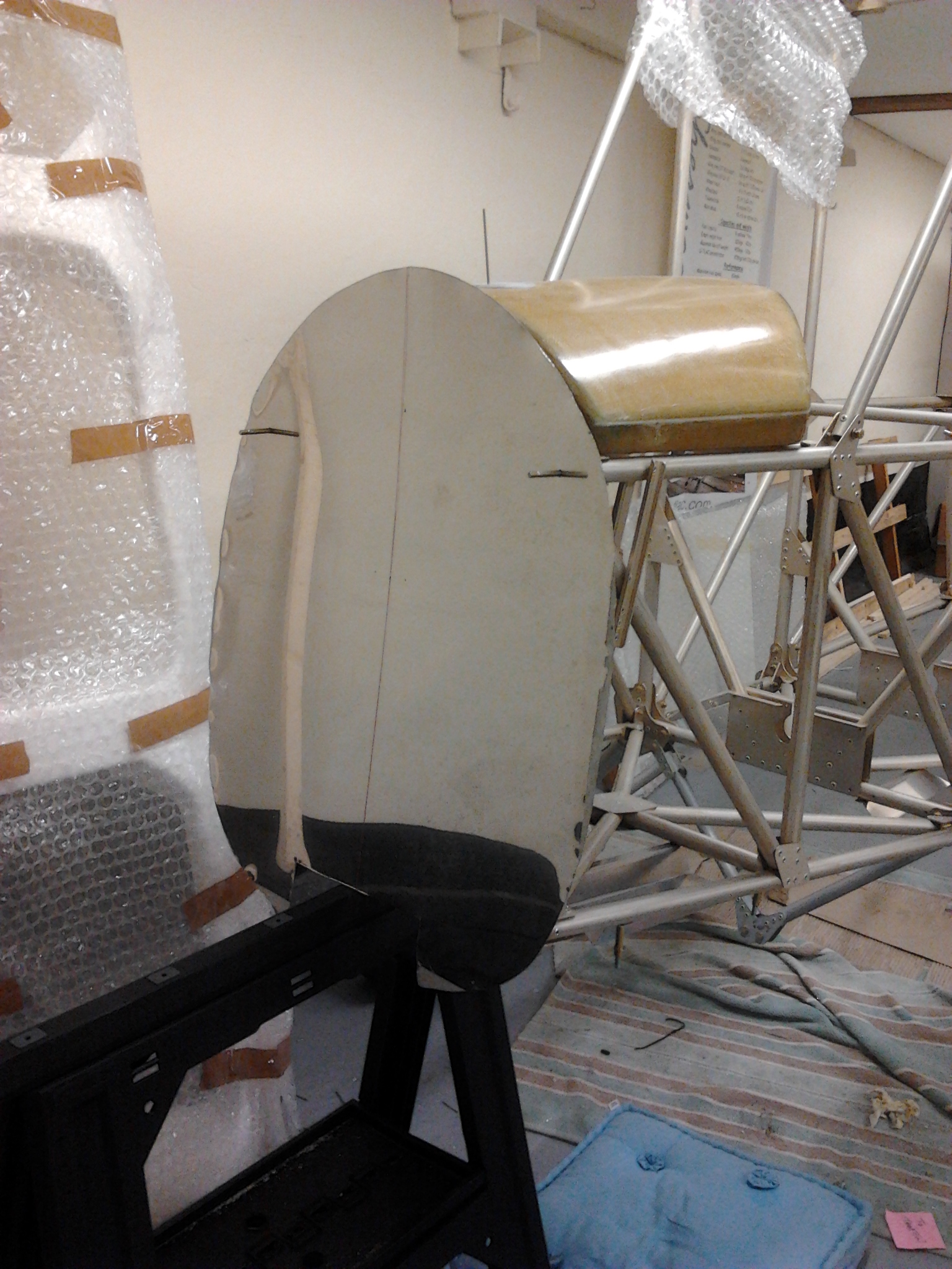
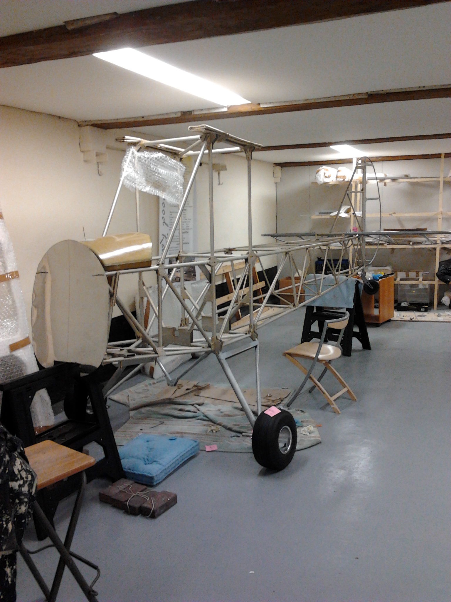
bulkhead 1b Bulkhead 1 Bulkhead 1bulkhead 1 a bulkhead first fit 2 Bulkhead first fit Bulkhead 2Engine bulkhead is cut from a sheet steel using the provided template…. note the indent duct which is for an add on folded exhaust section.

I was not looking forward to this step .. could end up looking a mess if you get it wrong ! and great if you get it right !

Used the template and heavy cutters and big gloves – cut edges double as Stanley knives .. only sharper

Then used the template to align centre vertical and cross check with copius measuring. Then overlayed template to nose and existing engine bolts to get these centre punched and then drilled … top two were spot on.

Next step is the fold in the bulkhead and top pilot holes before positioning to pick up lower engine bolts.

Blog at WordPress.com.

Up ↑