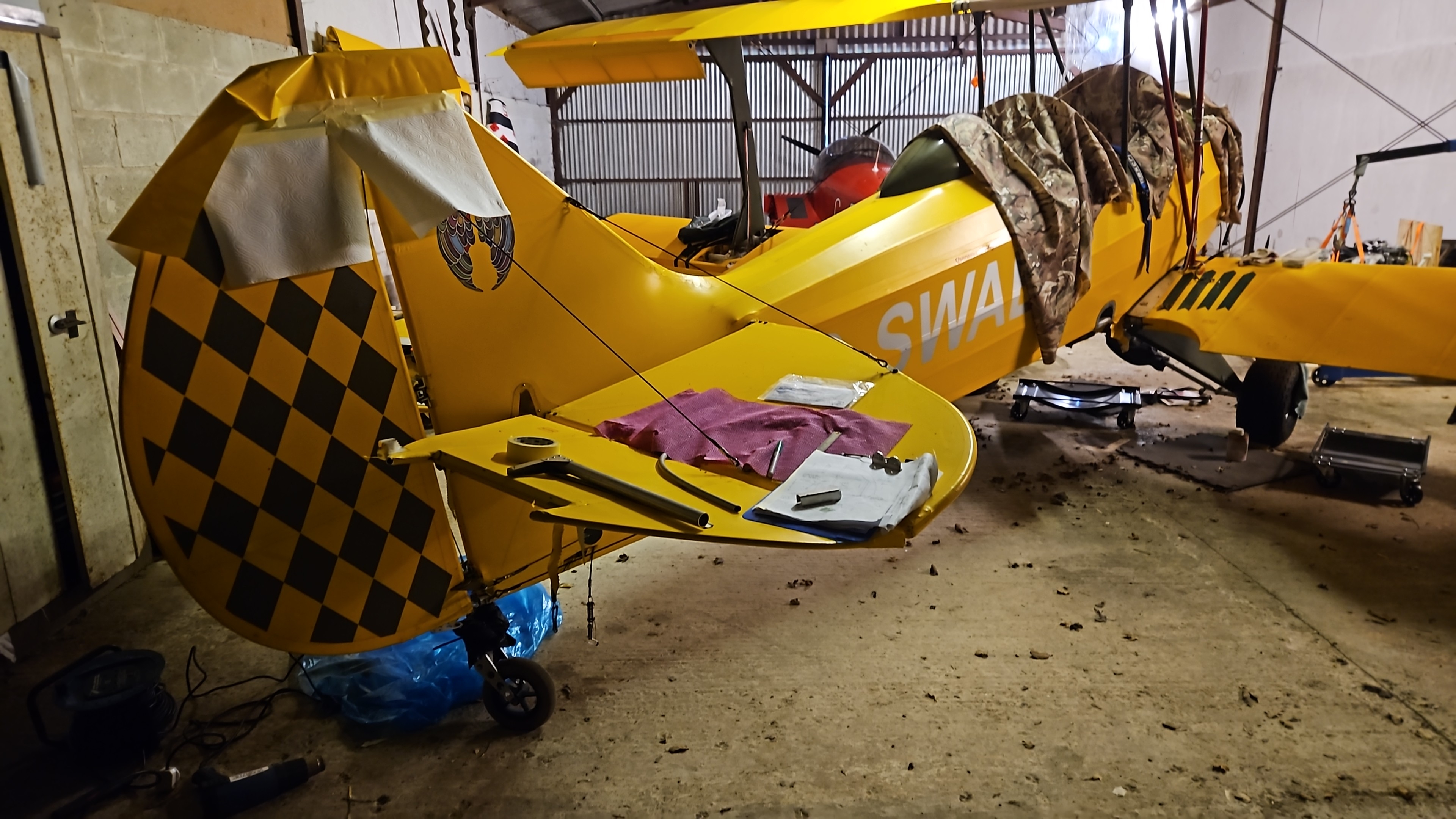
Inevitably, the arrival of an aircraft into a field of wheat..no matter how slowly … is going to make some marks on the paint and.materail
I have to say, the Oratex was incredible!
Thinking back, there wasn’t one scratch on the fabric! At all !
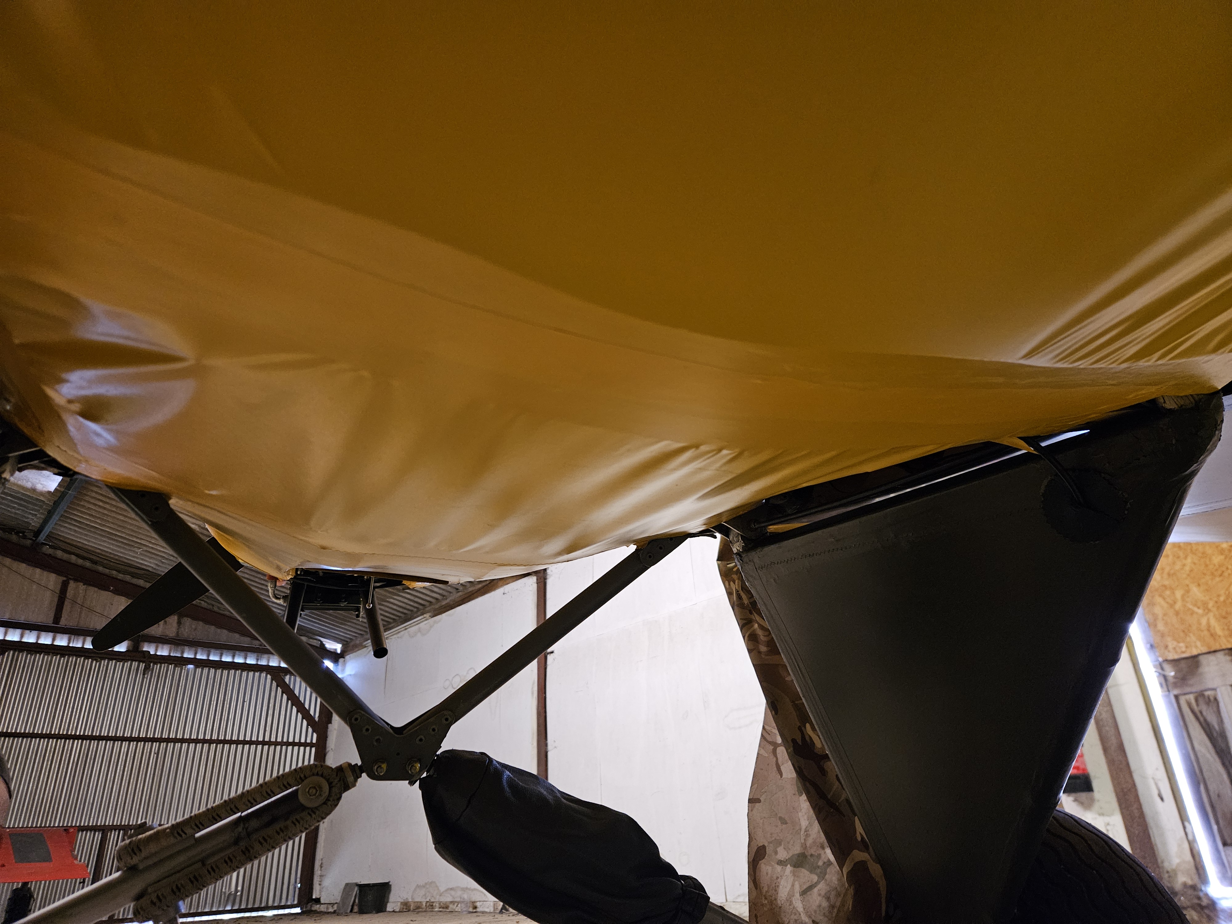
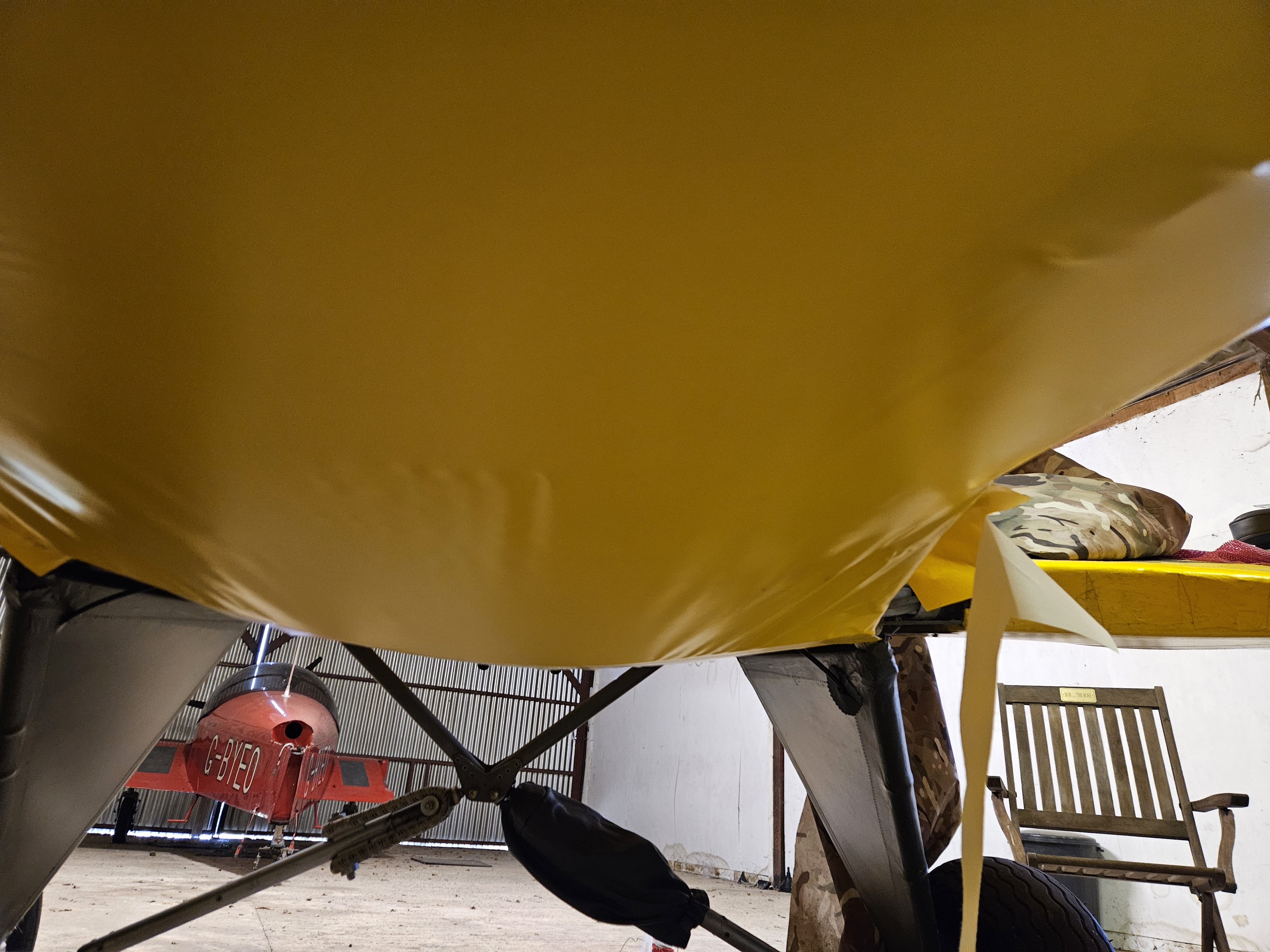
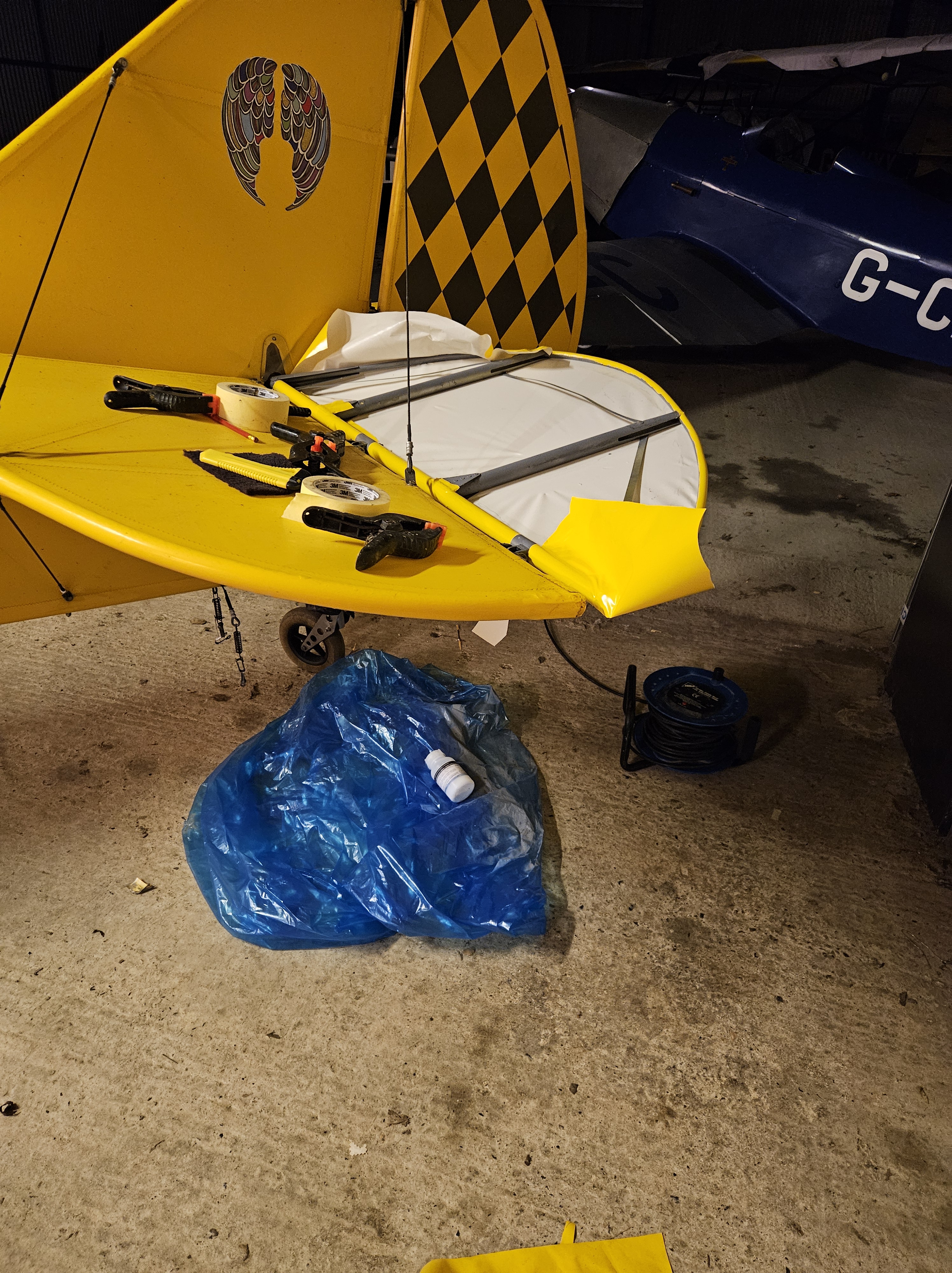
I had to remove all the fabric from the Port upper (for inspection to identify it was indeed repairable) .. i removed all underside from P1 back to the leading edge of the tailplane ..
But it simply didn’t have a mark on it.
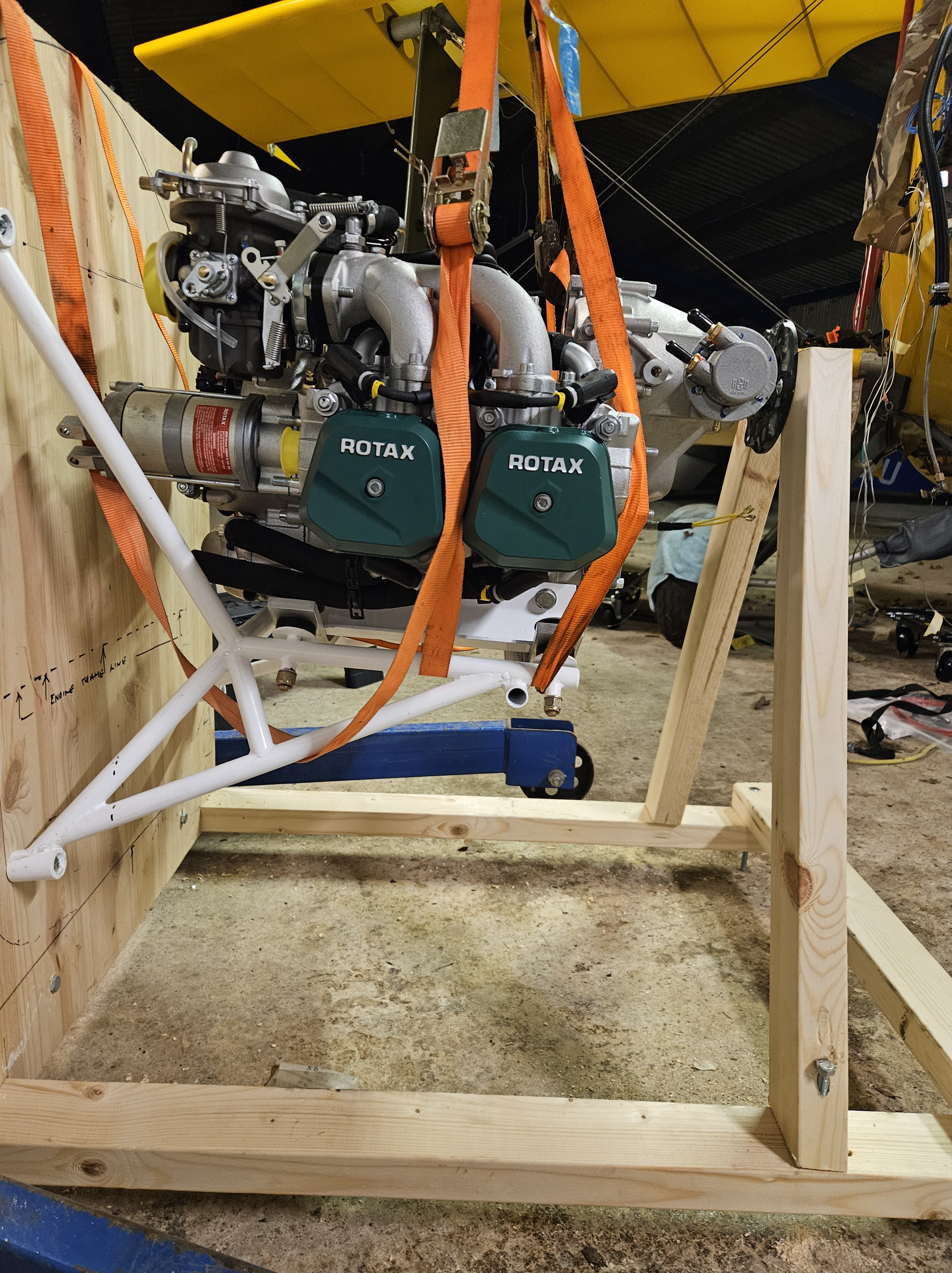
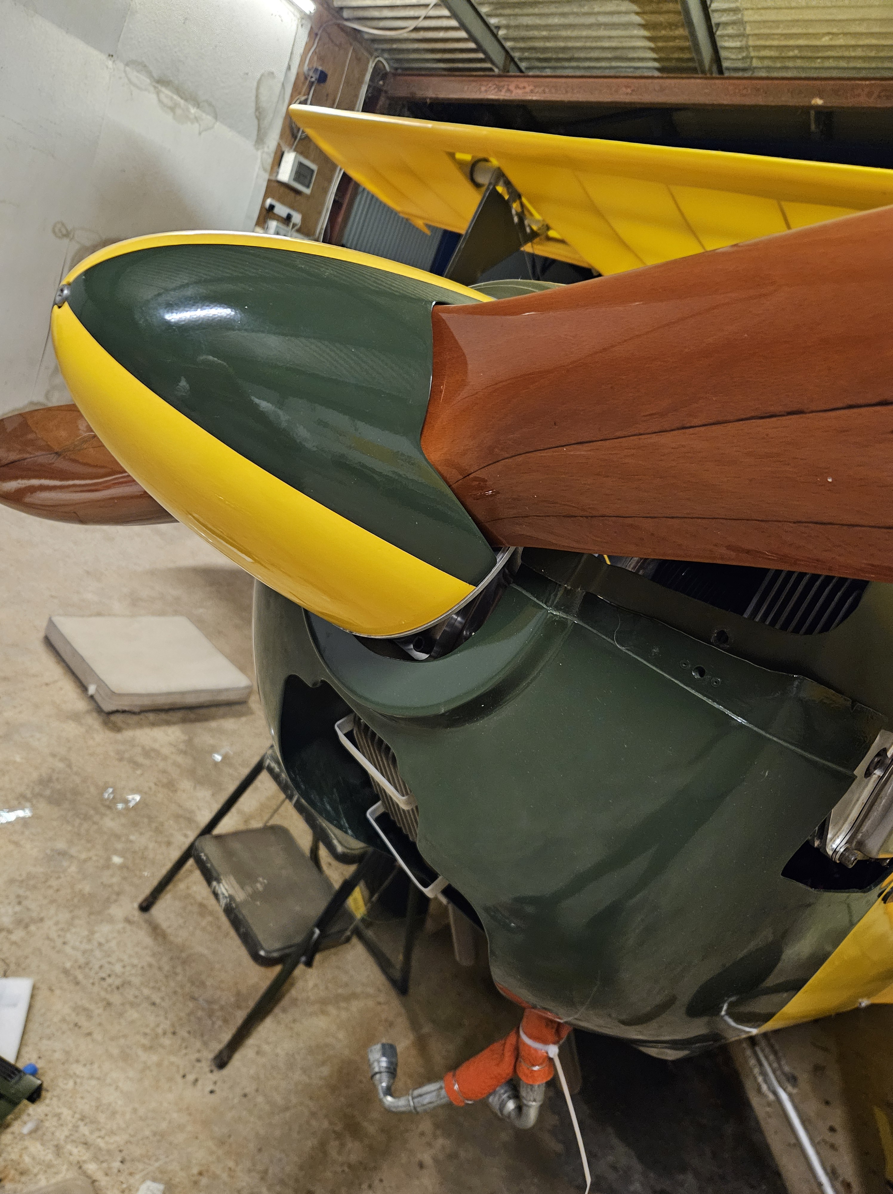
The lower cowl took the brunt from the crushing of ine of the most forward part ..the oil cooler matrix.
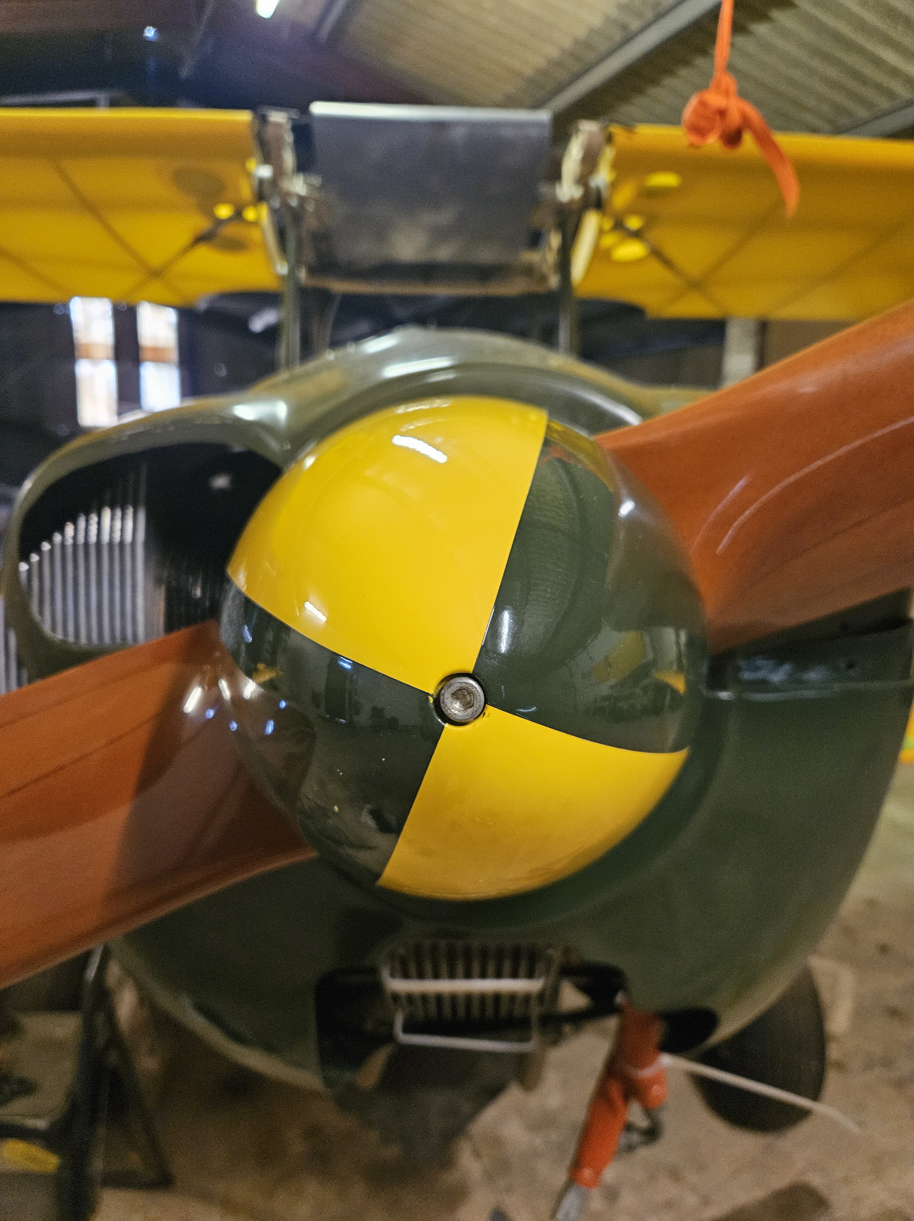
The spinner had quite a graze but I suspect that was from the recovery.. where we pirouetteed to take her back onto her main wheels
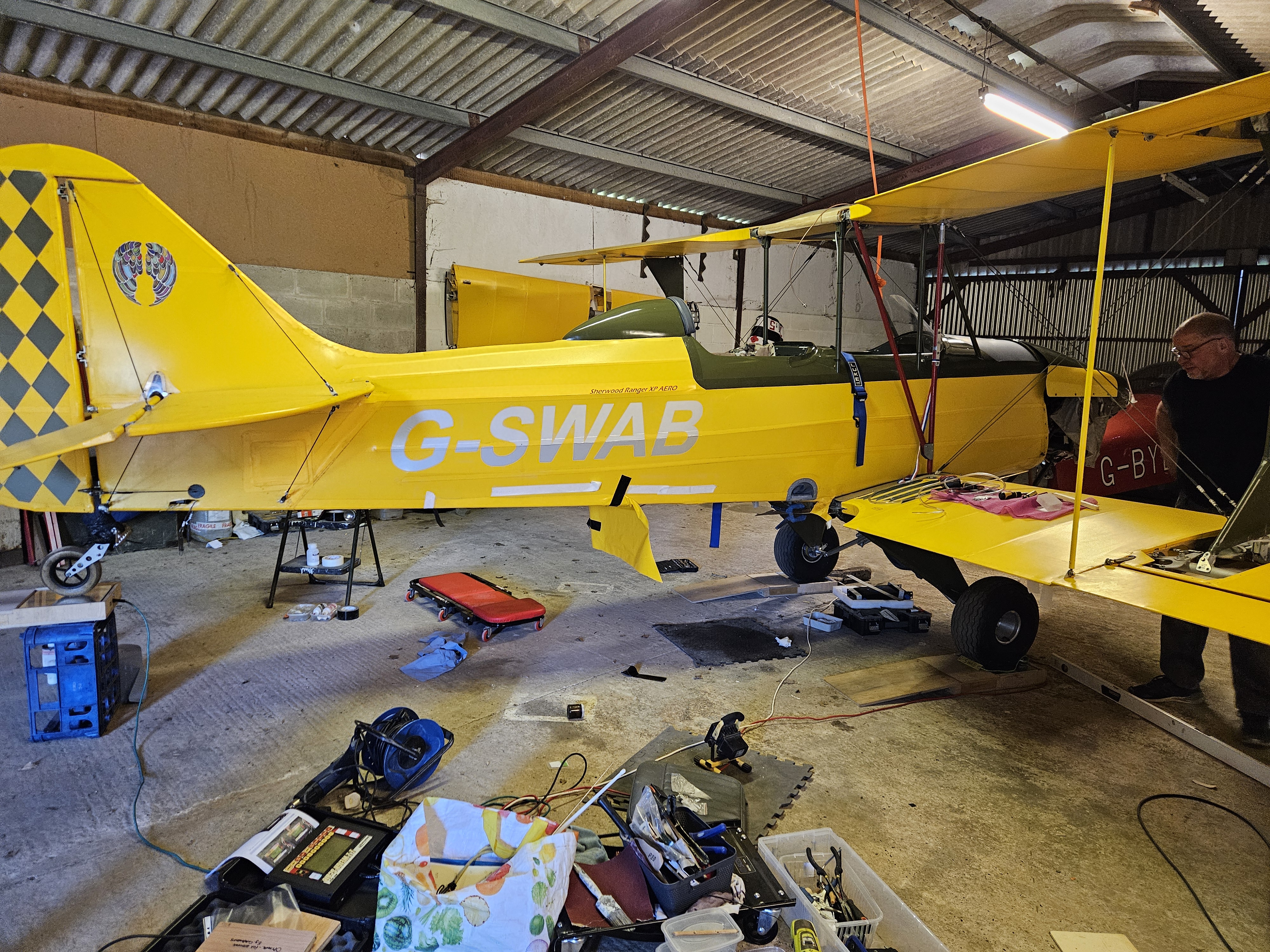
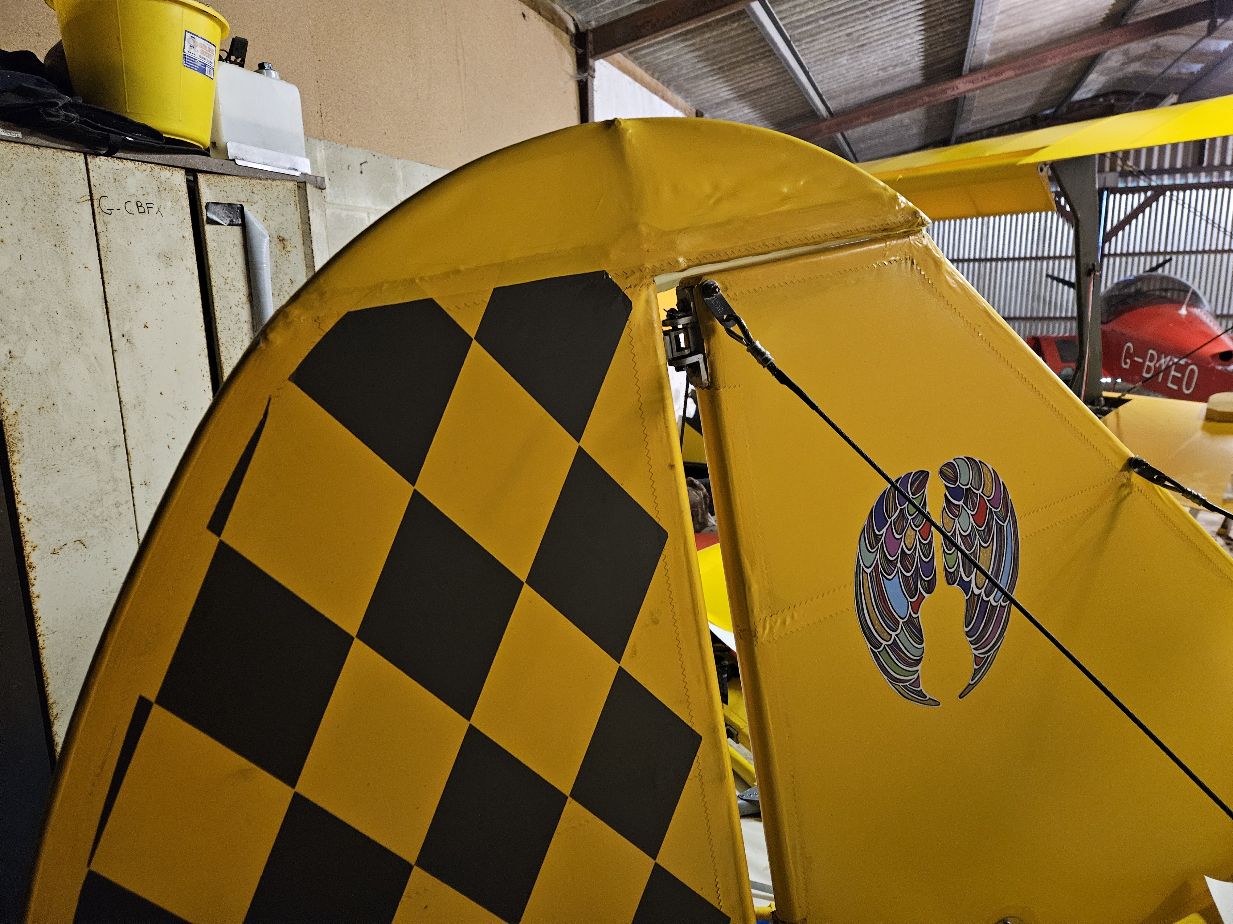
Roger, a great painting expert based at Priory Farm, stepped in and has done a amazing job.
The lower cowl, which had a number of holes to accommodate the exhausts and oil matrix, was reinforced with fibreglass matting before colour matching the olive Oratex and what a superb job !
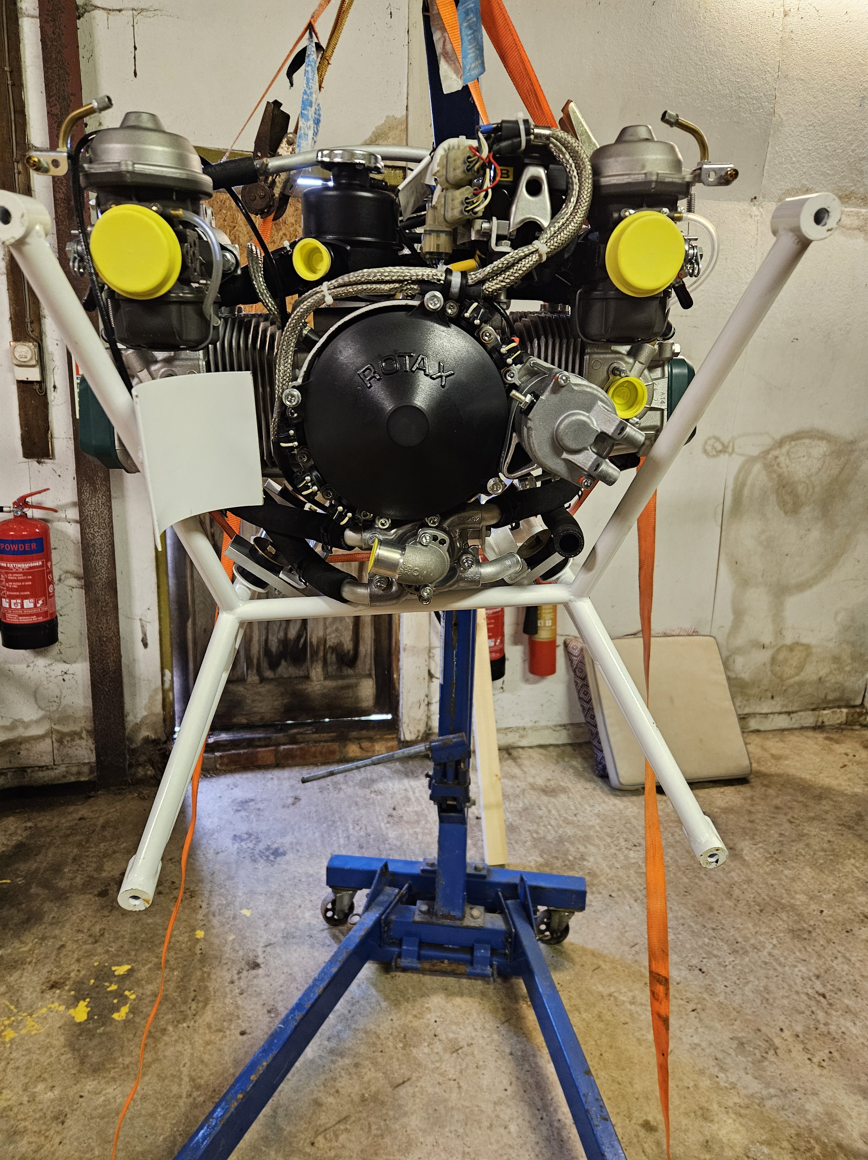
Now awaiting new oil cooler matrix cradle fit