Elevator intermediate horn

This is shaped and etched and spaced before applying rivet fixing on central spindle.

Intermediate Elevator horn Intermediate elevator horn 2

The intermediate horn sits between the seat rails and is positioned to pickup the ‘tail end’ of the elevator interconnecting rod (yet to be completed) that runs through the centre (internal) of the control torque tube.

Exhaust Duct

The exhaust duct is shaped from similar guage stainless steel sheeting as the bulkhead. Once shaped it has small flanges folded at the ‘leading edge’ to accept the mounting rivets.

exhaust duct

Seat Rails

The seat rails fit between various key parts on the body. They require mounting brackets to be profiled to clear rivet heads and the support members profiled to fit.

Seat Brackets

seat rails

Front Rudder Pedals

Rudder pedals are mounted on plates that sit just above the footwells.

The support brackets are drilled and shaped and then etch primed ready

Front pedal plate

Each pedal is bushed and the rivets pick up the main cross beams of the aircraft. The pedals are provided pre welded but need rubbing down, etch priming and then 3 coats of Hammerite.

Left rudder pedal

Bulkhead

bulkhead 1b Bulkhead 1 Bulkhead 1bulkhead 1 a bulkhead first fit 2 Bulkhead first fit Bulkhead 2
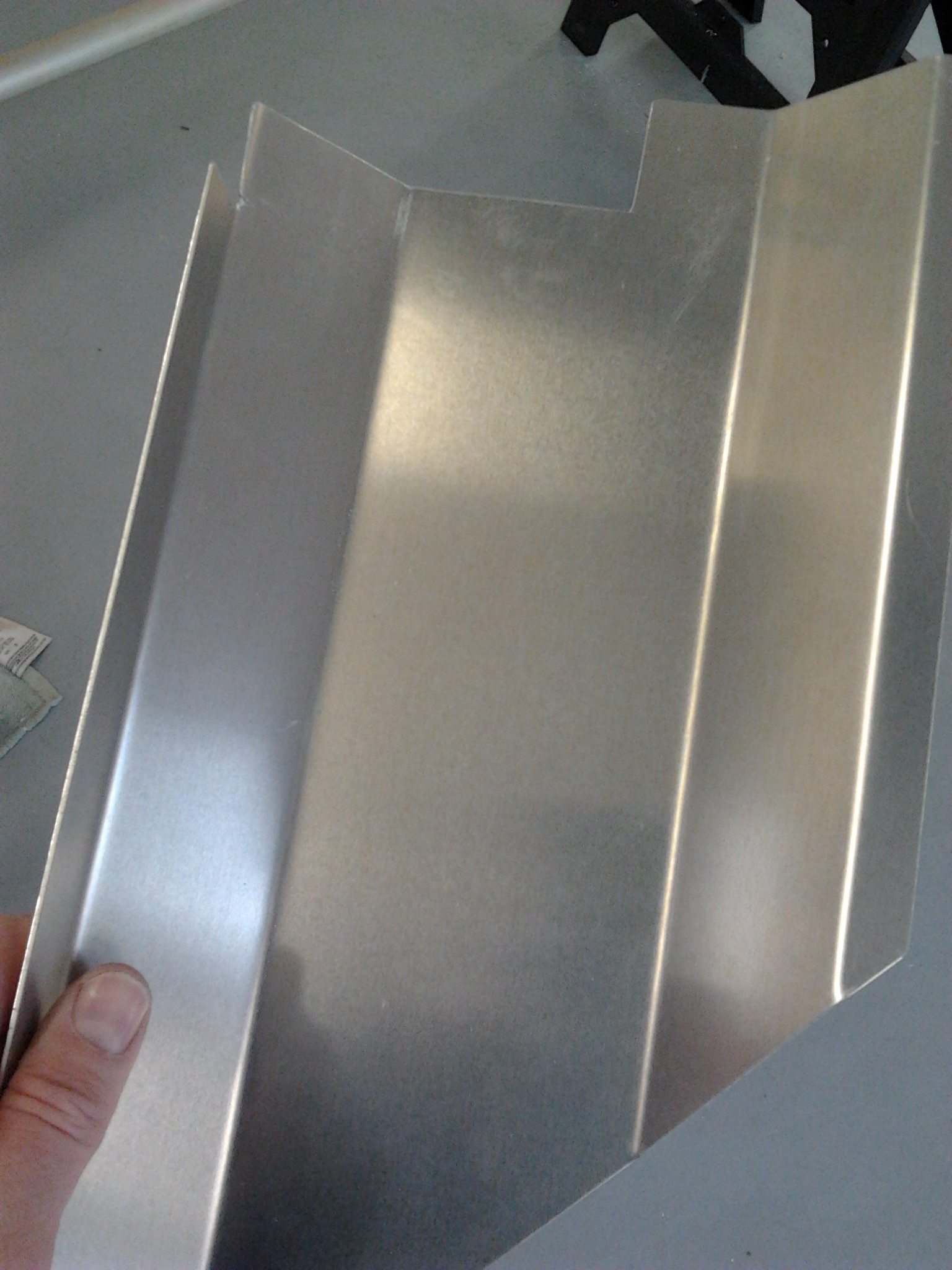
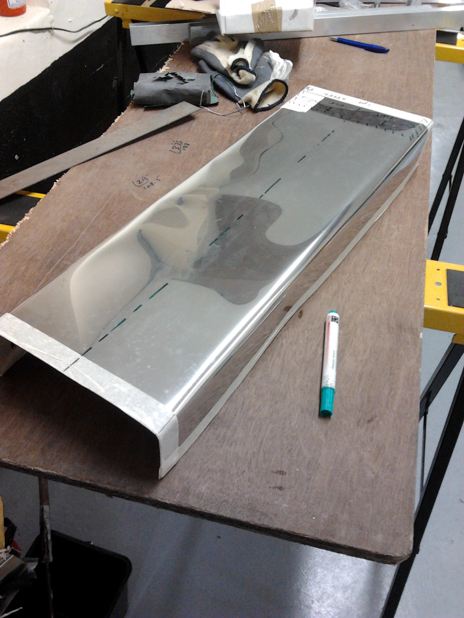
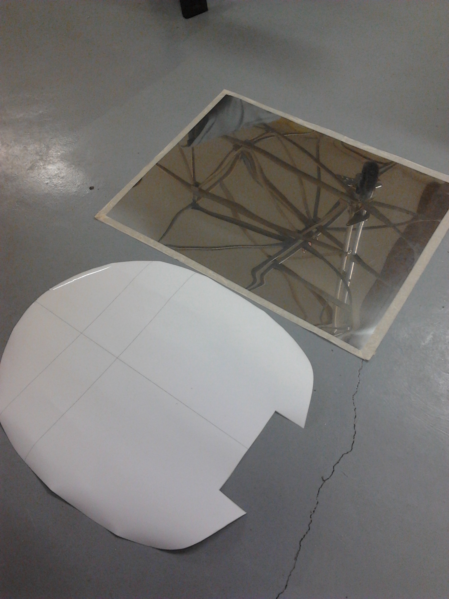
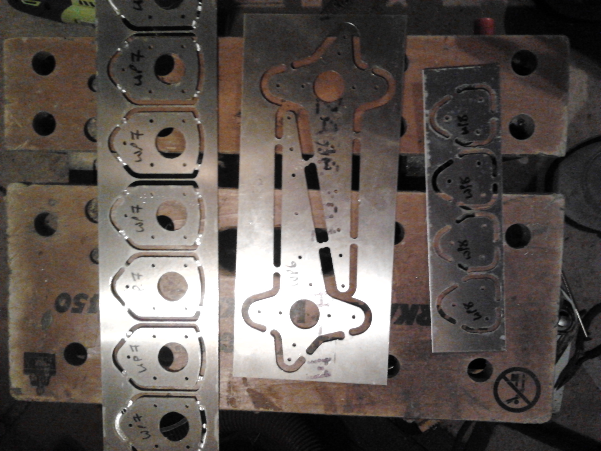
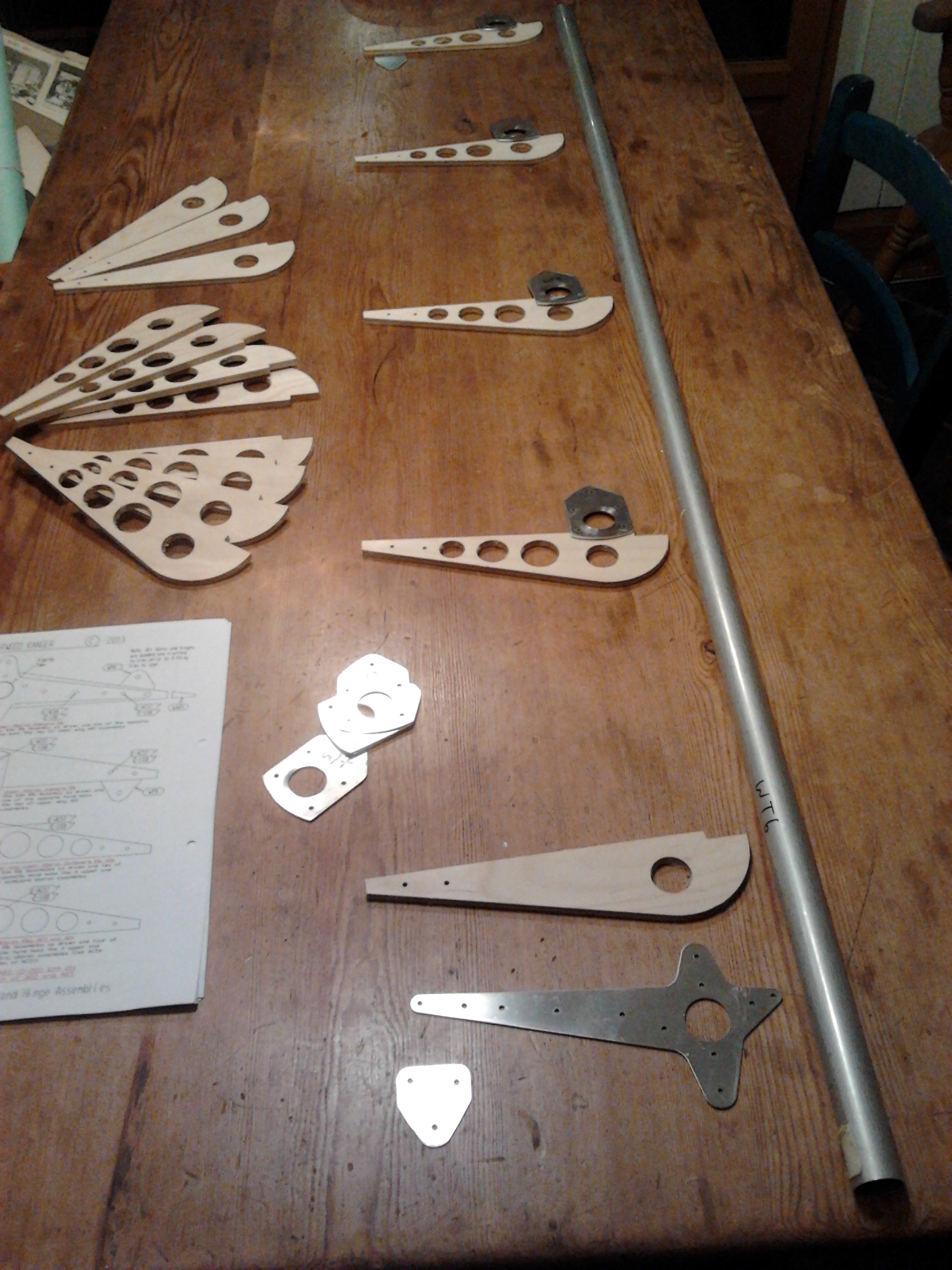
Engine bulkhead is cut from a sheet steel using the provided template…. note the indent duct which is for an add on folded exhaust section.

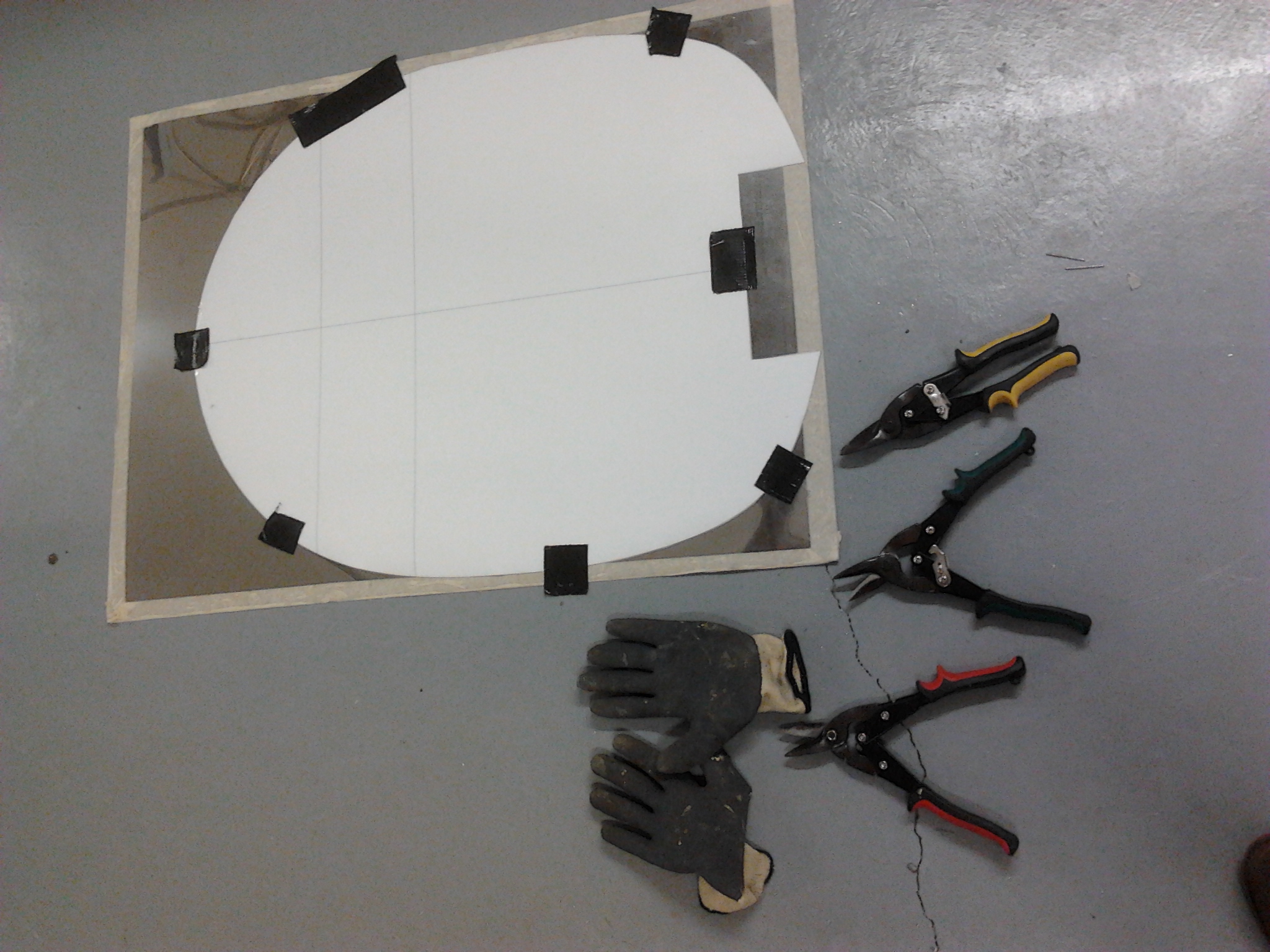
I was not looking forward to this step .. could end up looking a mess if you get it wrong ! and great if you get it right !

Used the template and heavy cutters and big gloves – cut edges double as Stanley knives .. only sharper

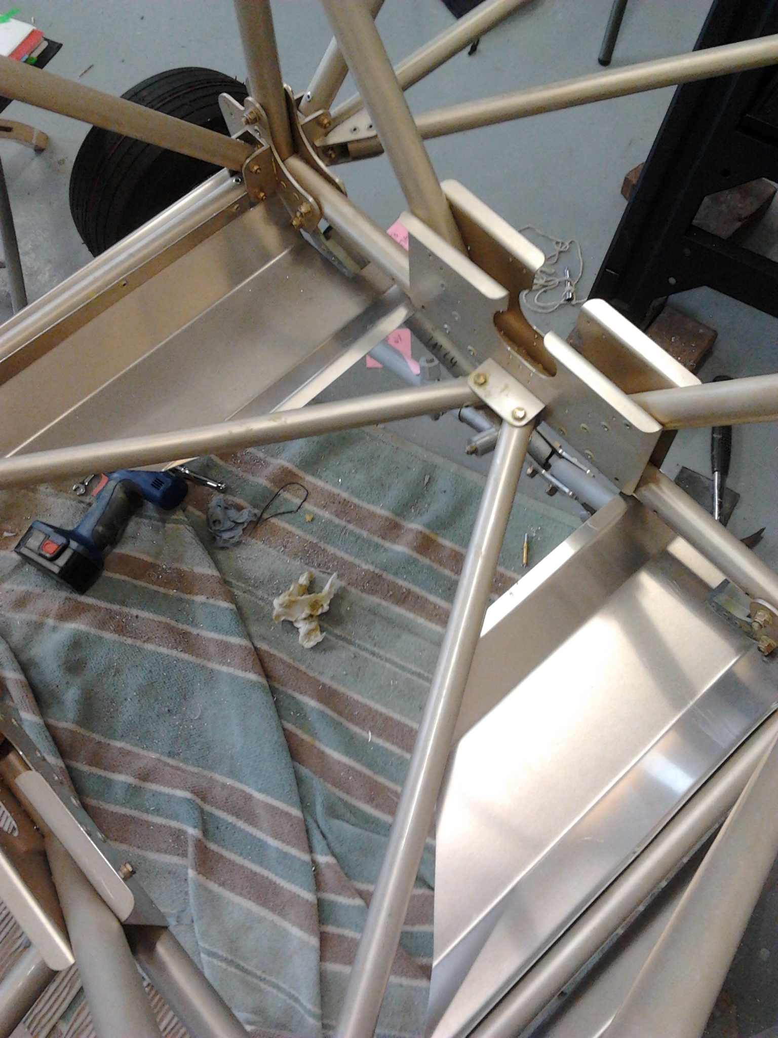
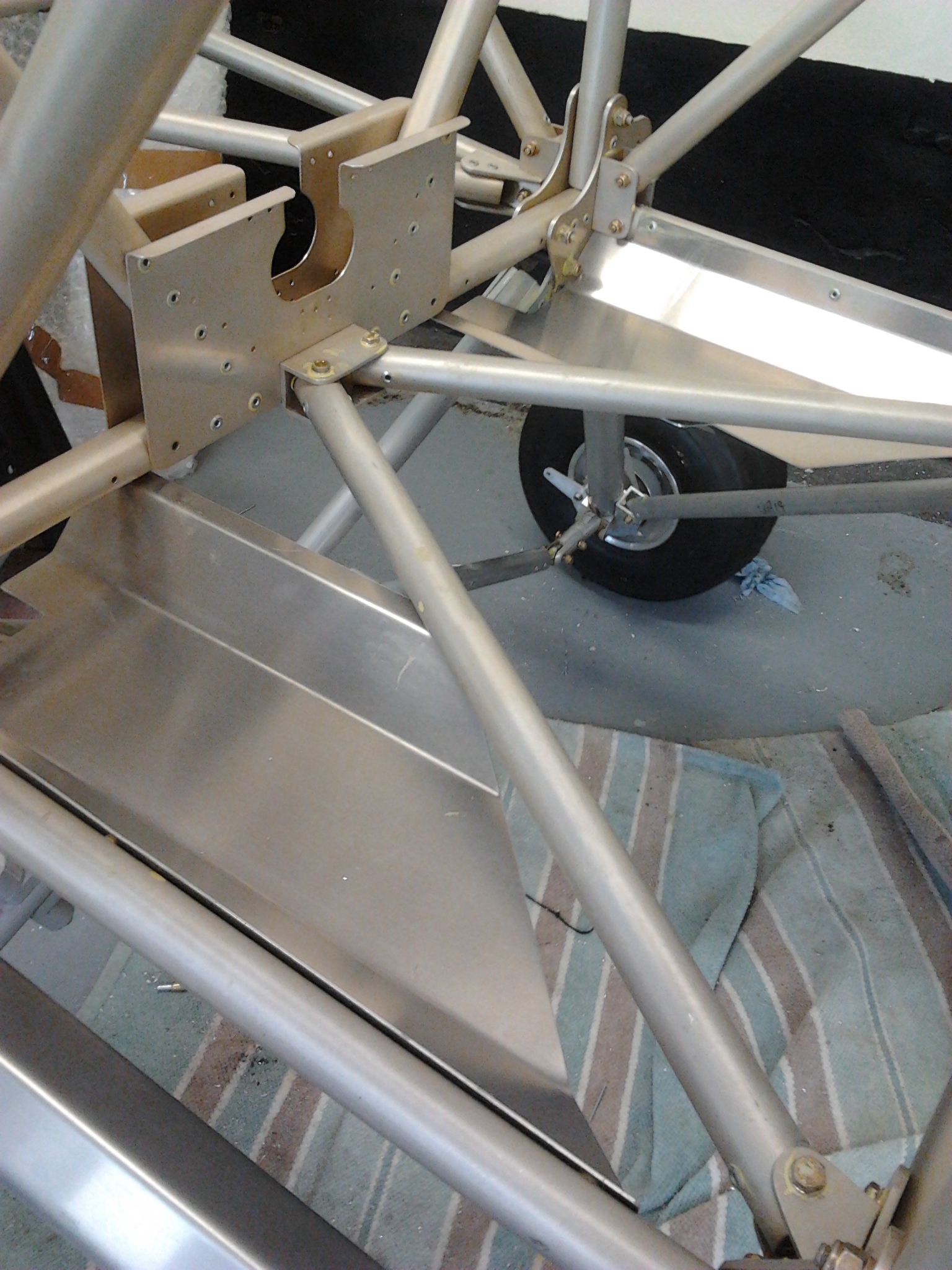
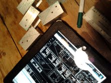
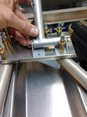
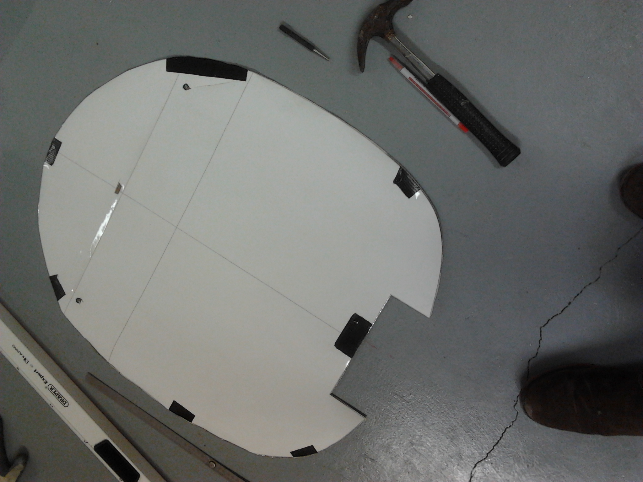
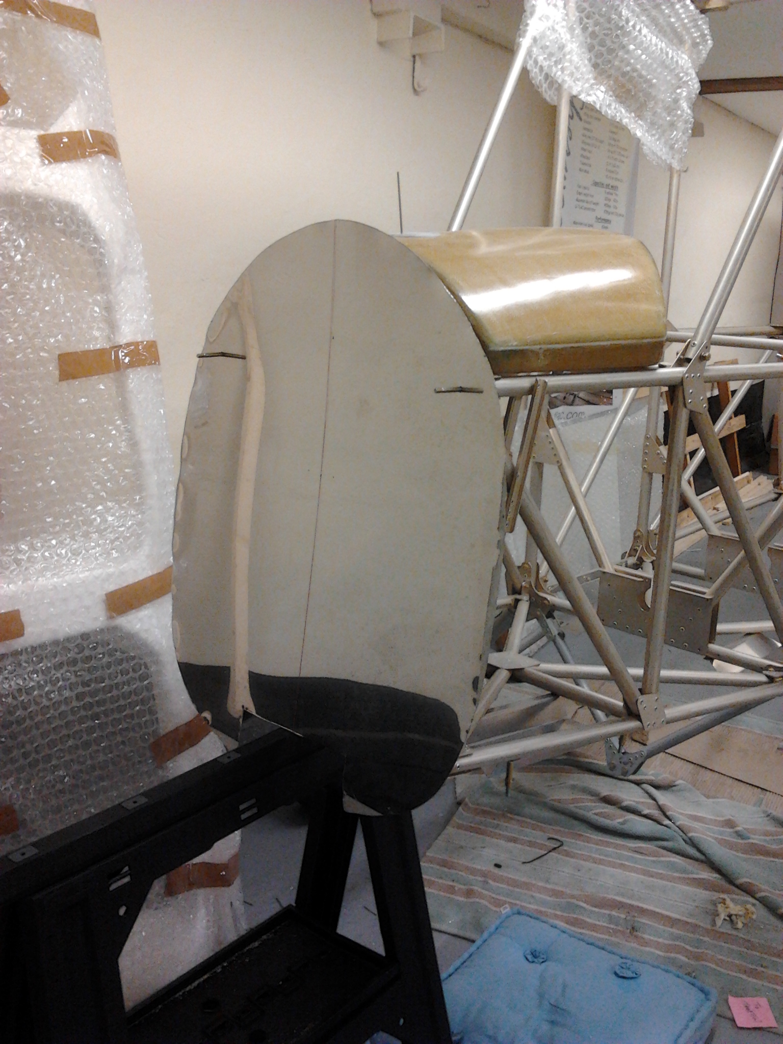
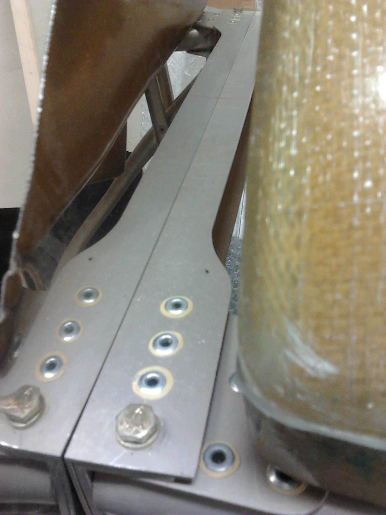
Then used the template to align centre vertical and cross check with copius measuring. Then overlayed template to nose and existing engine bolts to get these centre punched and then drilled … top two were spot on.

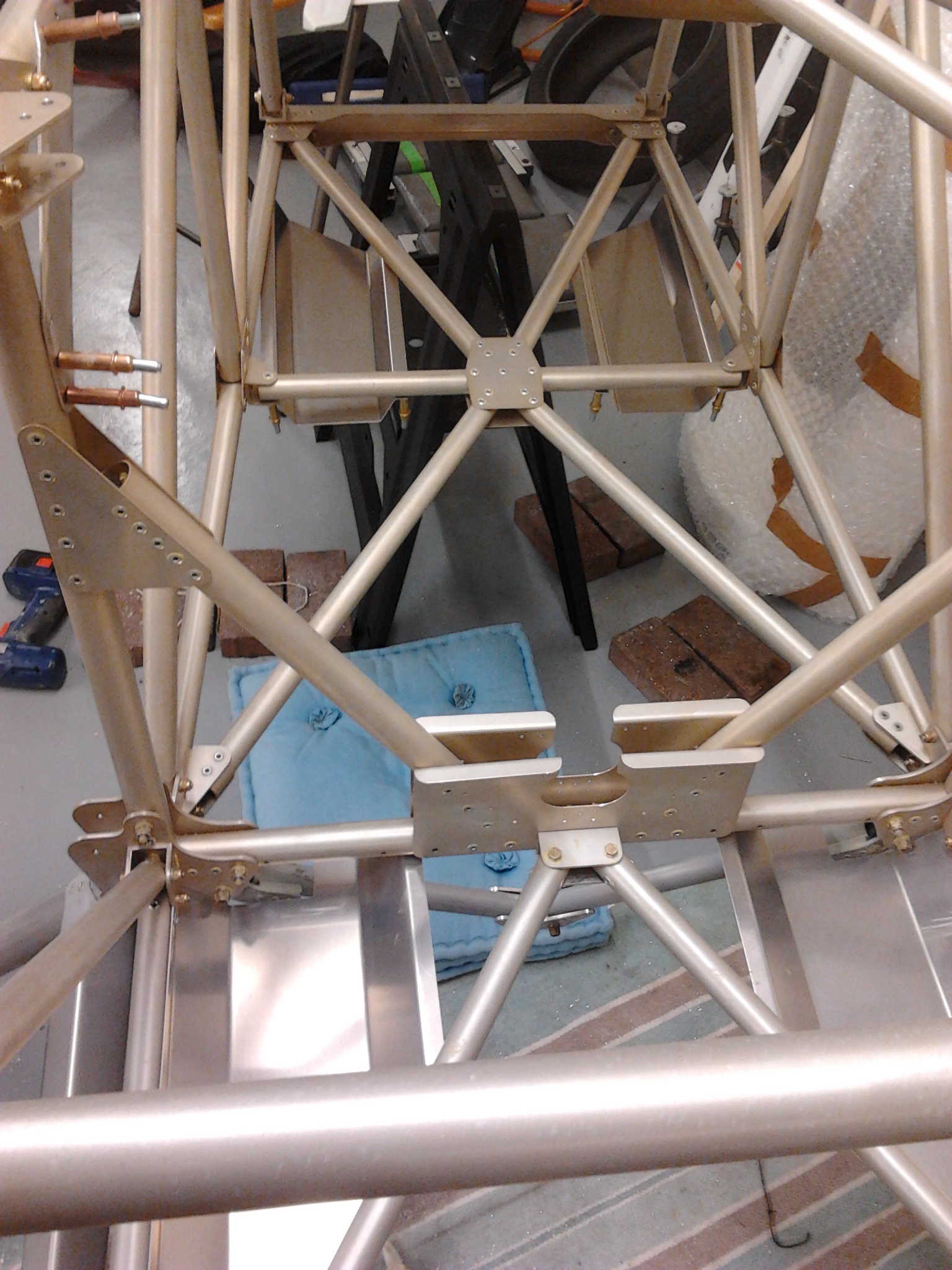
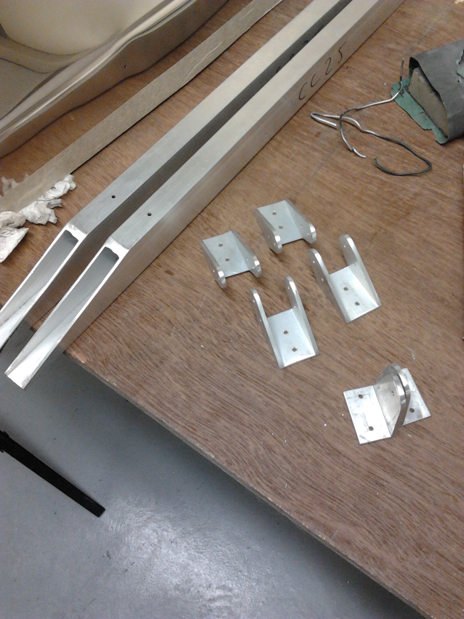
Next step is the fold in the bulkhead and top pilot holes before positioning to pick up lower engine bolts.
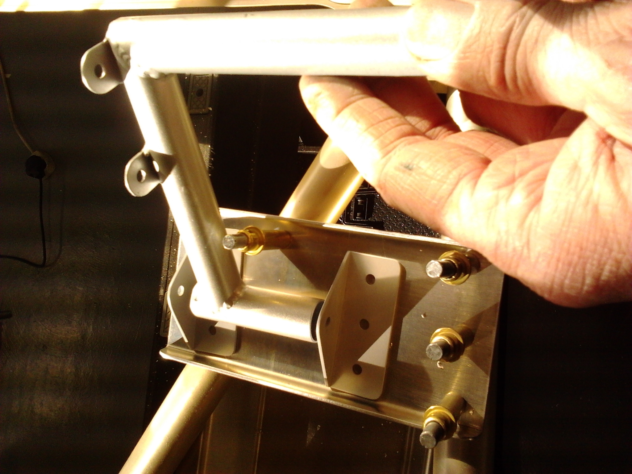
Ailerons – Start to prepare by shaping ribs

Aileron ribs are CNC pre (part) cut. Thicker ones are 6mm ply and need rubbing down for prep to test fit to aileron spar

aileron pre cutaileron prep1

Tucked up above my garage as the Force 6 outside winds its way up to  Force 8 its quite cosy cutting out ribs and bracing sections. Supposed to be nipping to Guernsey tomorrow in a Cherokee Six but forecast F7 Northerly’s on an E/W runway is not conducive to keeping the legs straight !

Footrests Rear (Pilot) ones first

Footrests are largely pre folded metal but require  little shaping to fit between body stringers

rear footrest profile

Had to loosen and move the two centre bracing bars that were factory fitted so you can get a drill square onto the rear of the footrest and drill into longerons. The bars moved out and then relocated with fresh duralac to fit snugly again.

Rear footrest 2Rear footrests 1

Front ones next

Front footrests

Throttle levers and Links

Moved from the tail end this weekend to start work on the cockpit area.

The first step is to shape and fit throttle support brackets and then start to locate these on the left hand side.

Lay out parts of the throttle linkages before assembly

throttle parts

This picture below shows after initial (first fit) … with bolts securing top two positions … one of these is changed to use a knurled stiffener top which is provided with the kit

Throttle 2

Blog at WordPress.com.

Up ↑