Aileron – Leading edge – Scarfe joint

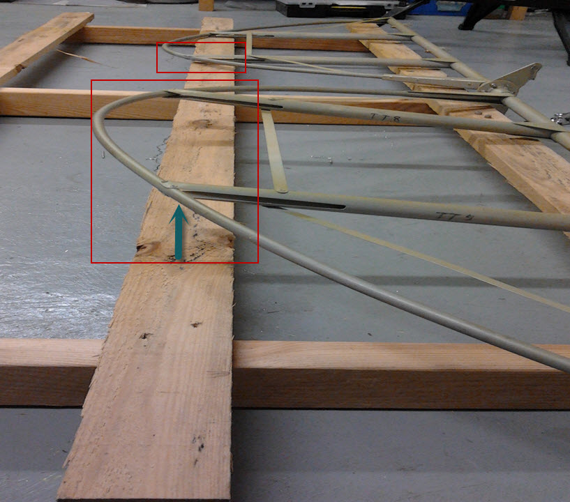
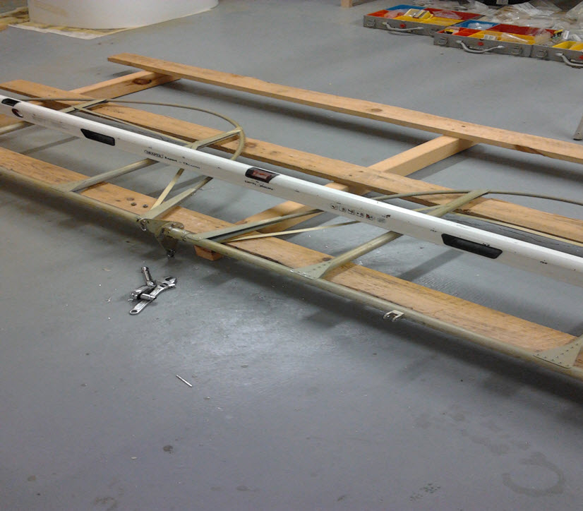
The leading edge ply for the aileron leading edge is 0.8mm so quite plyable … only problem is that it is just too short for the length of the quite large ailerons … this means making a scarfe joint to butt two pieces of ply together to make up the length.


Having read up on the internet exactly what a scarfe joint is … basically a layered joint to ‘blend’ one piece over the other. The internet was useful in that it gave advice on how your new joint was squared up … ie sanding using a hard block on the edge of a solid surface … then checking that the various layers (3 in this case) reveal in a straight line … then you know your chamfer is square


First Inspection

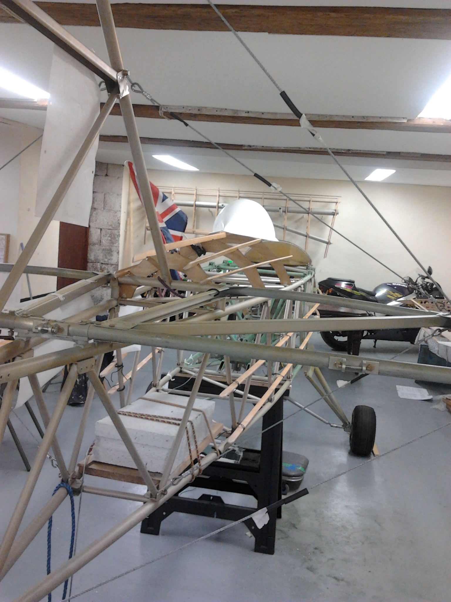
Been getting the plane and workshop ready for the first inspection. All the relevant build digrams have been stuck to the airframe in the proper place to make checking easier.

Fingers crossed as I cant continue with other cabling and top deck bits until that is approved.

Preparation for Rigging

To prepare for the tail rigging I need to remove the rudder

and then the Elevators

This gave me a chance to complete the Elevator horn alignment – angles on a 60 degree forward rake to pick up the cables from the intermediate elevator forn mounted under the pilots seat.

Turtle deck

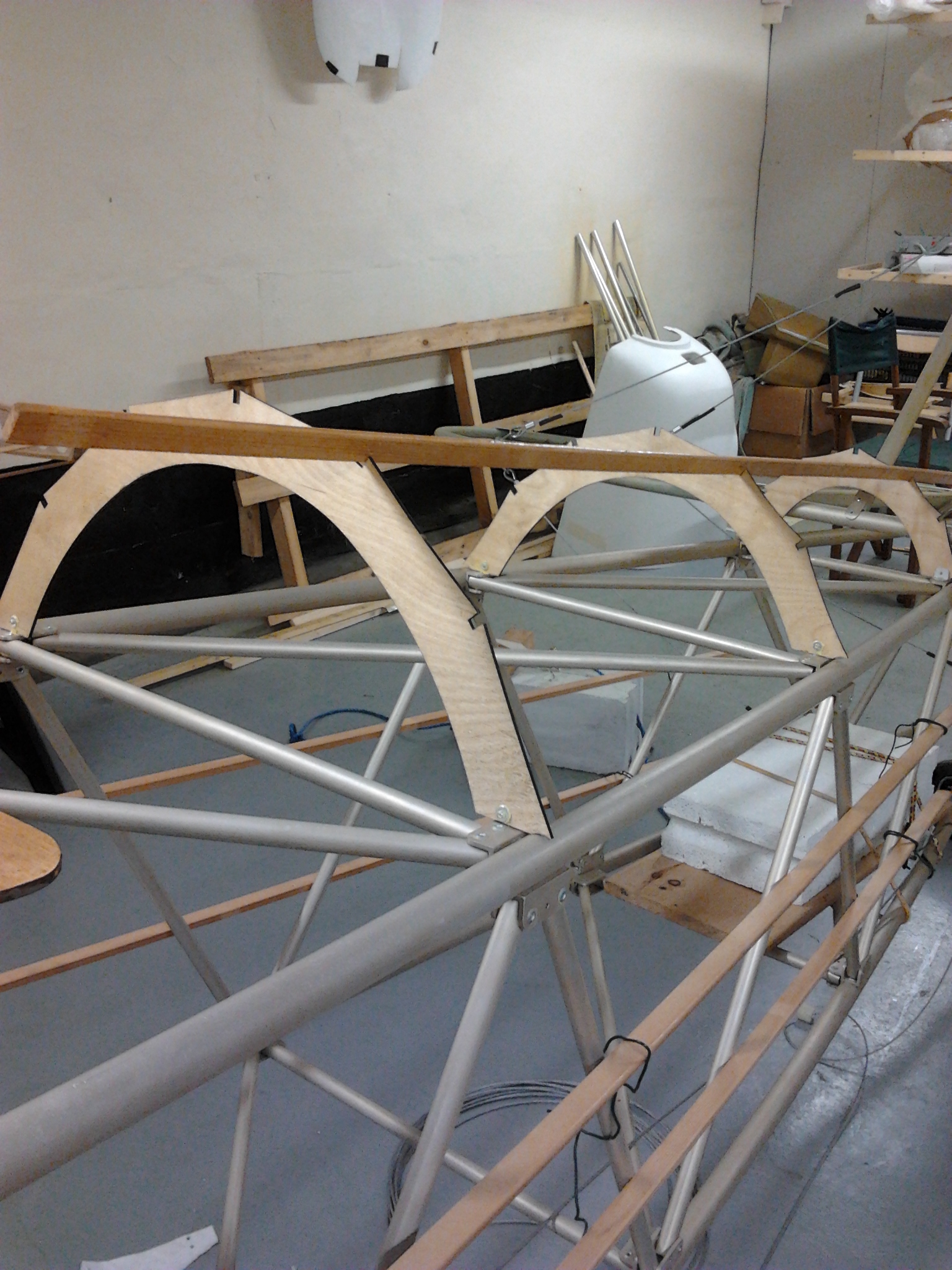
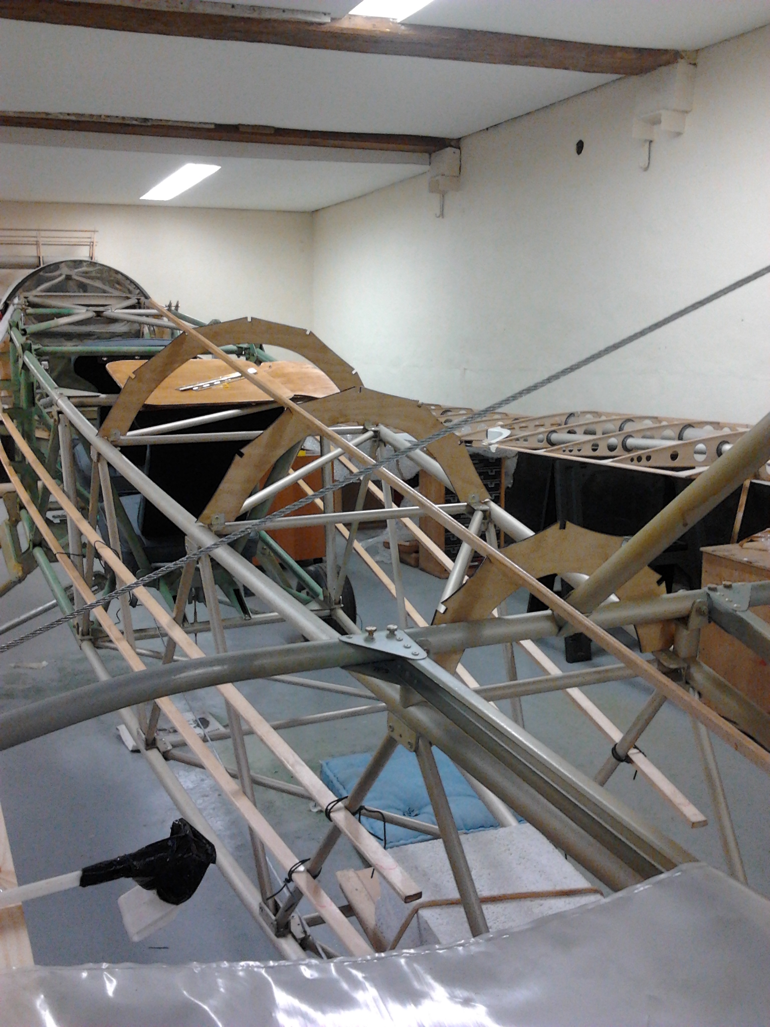
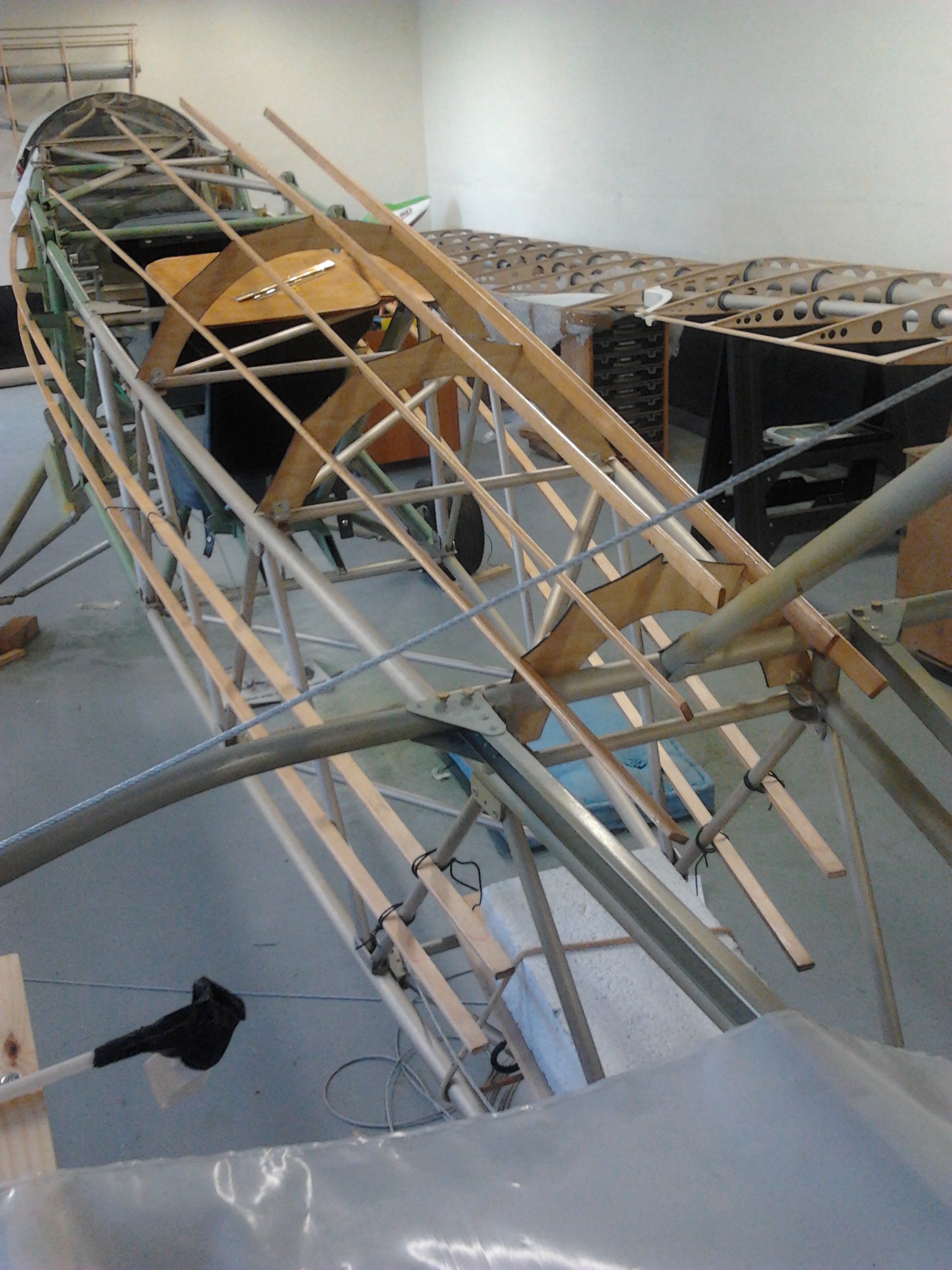
The turtle deck consists of some pre jigged ply former tops (3) and some beech strips.

The ply formers are riveted in position with small alloy angle brackets and the 5 beech stringers change the squared flat top in readiness for a more round finish which will eventually be covered in Oratex.

 turtle 1 turtle 2

The beech will need to be trimmed so that it tails off at the tailplane and buts up to mate with the moulded cockpit surrounds. The headrest then fits in the same way with small angled brackets riveted to the beech top stringers.

Turtle deck 3

Aileron Jig

To save a treck up to the barn for every build item I have repositioned all the aileron parts to my garage roof !  Now, with a jig built and a temporary rack setup so I can ensure I have a LEFT UPPER, LEFT LOWER, RIGHT UPPER, RIGHT LOWER ..

Need to make sure all metal rib doublers are in alignment and also that the rivets are countersunk and duralac’d with washers on wood facing sides

The jig lets you align and fix securly the lower leading edge spruce and the trailing edge spruce strips. I have used screw jig points to double check vertical and lateral alignment

aileron jig

Top Deck First Fit

Having carefully removed the top cabane (which needs top centre ribs fitting and shaping) I offered up the top deck for its first test fit and alignment check

top deck 4 Cabane top deck 3

Top deck 2 Top deck1

Rudder cables first fit

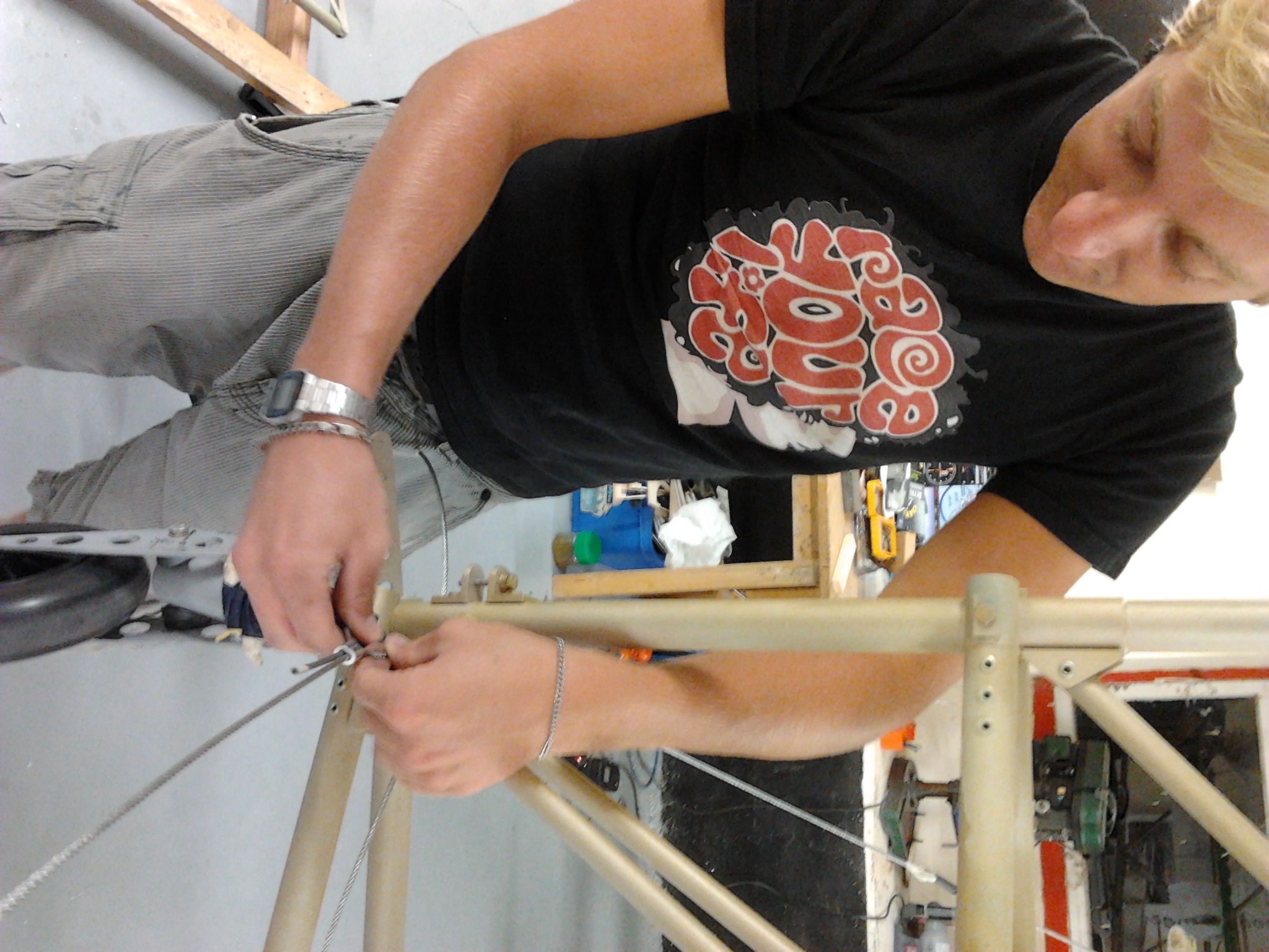
Having successfully cocked up my first two attempts at using the Nicopress crimper (kindly loaned by Channel Island Aero Services – you are a star Bob !) I finally got the hang of how much to leave as a ‘tail’ .. 64cm exactly between front (passenger)  and rear (pilot)  pedals .. so made a small jig ..

rudder cables 1

Heat shrinks yet to be heat shrunk !

Rudd cables 2

Cabling – A new Challenge and Learning !

When I was up at the TLAC factory in Norfolk last month Paul kindly stepped me through what putting a cable together entailed.

Ferrule 1Ferrule 2 

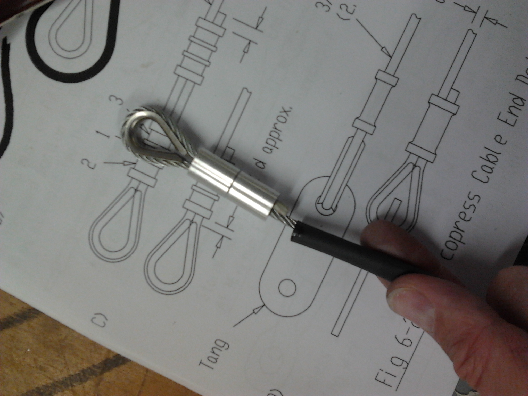
First you wrap a short piece of masking tape very tightly around the cut point of the cable. When you then cut it doesnt fray all over the place. You then get your FERRULE and place it in the SWAGER (the device that compresses the ferrule onto the cable) passing the cable around the THIMBLE and back through the ferrule. Pulling the cable through to adjust to length BEFORE clamping so you dont have to post trim.

Take care to thread two ferrules onto the cable if it calls for it PLUS the heat shink cable – difficult to slot on afterwards !

After the first press (in the middle)  you remove, turn through 180 degrees and compress again. Then you do the same one end and then the other. This ensures you have an even grip over the length of the ferrule.

Not posessing a swager – South Pier Ship Yard have kndly offered to let me use theirs (very many thanks Ed !) who has shown me some of the very neat job he does on their boat cables.

First step will be to accurately measure the point to point between the front rudder pedal and the pilot rudder pedal – as these are the first I will try.  As Ed suggested, mark where the cable ‘peaks’ over the Thimble.

Why is it taking so long !

The main question people ask when they see it is ..  “How long before its finished ?”

This is always a difficult question .. you are constantly having to learn new things and so estimating something that you have never done before is not a particularly exact science !

  • Riveting
  • Engine
  • Etching
  • Drilling Stainless Steel
  • Cabling
  • Covering
  • Wiring
  • Balancing

Also, if you are sensible, and pay attention to the small details .. you end up walking away from the barn with a satisfied feeling … although there have been times when that rivet that didnt sit flush … nags away at you and there is no alternative but to carefully remove it the next day and GET IT RIGHT !

The ‘Small stuff’ like rounding the corners of every sharp edged or square edged item by cutting, filing, then smoothing with emery which then removes the initial etch prime – so you have to touch up all takes time. But they jump out at you when they havent been done !

The project now has a number of concurrent strands running which means you can spread the interest/load and complexity. So if I hit a snag I am not stopped dead but can move on with other things. Current ‘strands’ are:

  • Engine – its in – but now needs air ducts, cabling, cooler shrouds, fuel lines, solenoid, regulator, RPM guages, Oil temp, Oil pressure etc
  • Stringers – the 2 long ones on each side are in and brackets being shaped – need to fit to front end, taper at rear. Belly stringers will be riveted in place once exhaust duct is filed smooth.
  • Controls – Torque rod done, sticks done, drilling clevis bolt for split pins, rear torque rod to complete
  • Bolts – all to tighten and paint mark – ready for Inspection
  • Ailerons – First (Lower Left) underway with rib location marked on spar, ready to tag glue then fibreglass

So lots of things running concurrently to keep me busy !

First Stringer on

Stringer fix

The stringers are long bits of beech or spruce that run alongside the body and change the shape from a boxed off section to take the curve of the material/covering.

The short ‘V’ shaped brackets that TLAC provide are tailored to length the further towards the tail that you go (for the side stringers)

Preparing the stringers takes around 2 hours each to round of the edges, then treat with 50% thinned polyurethane nefore another sanding, then final coat of full 100%.

They then slot part way through the ‘V’ and simply peg with a dowel – neat and simple !

Blog at WordPress.com.

Up ↑