Managed to get a heater to warm up the body before spraying (thank you Colin !). Jet style oil fired heater soon had sauna like conditions in the barn … Masked off the key parts
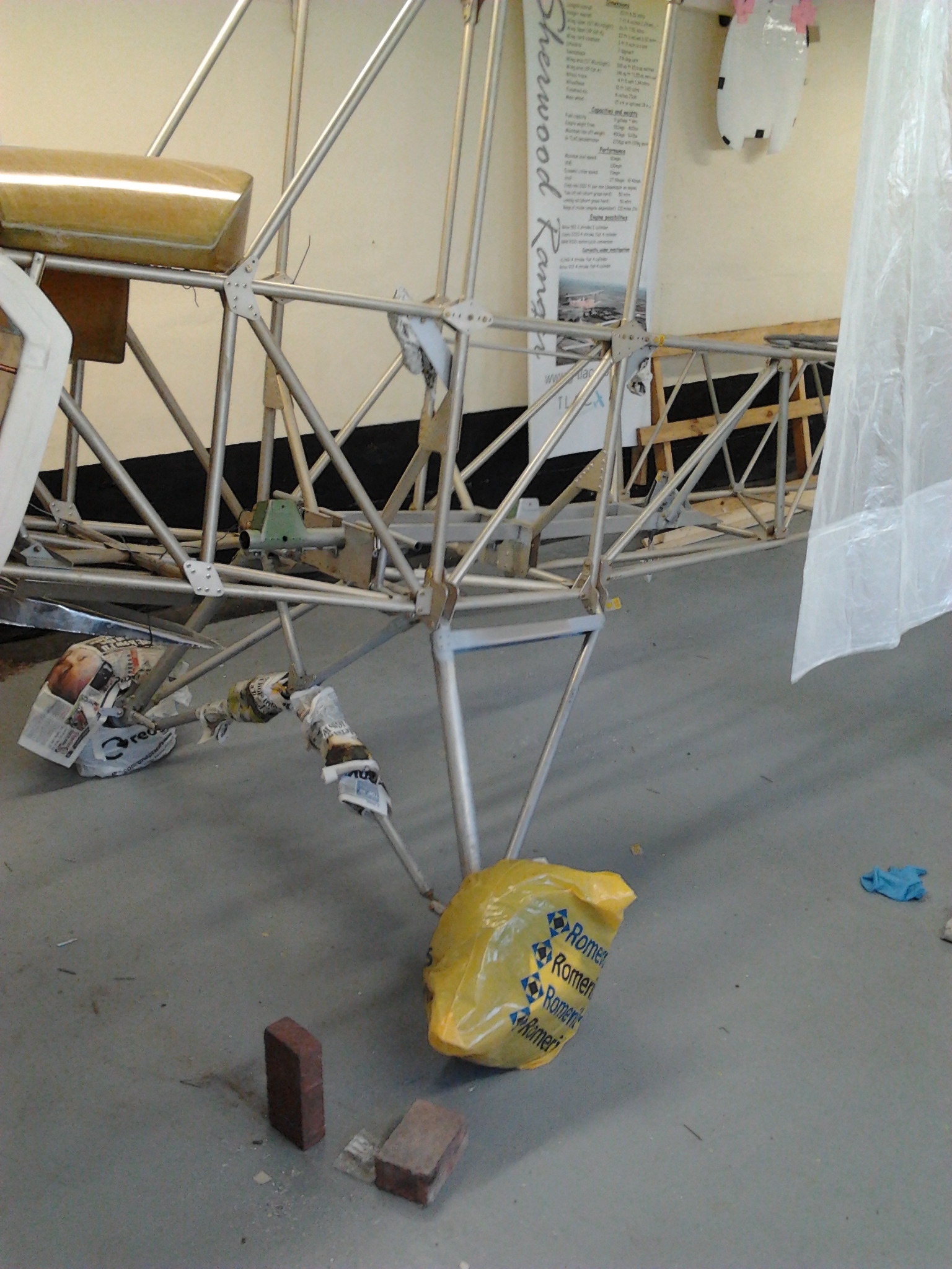
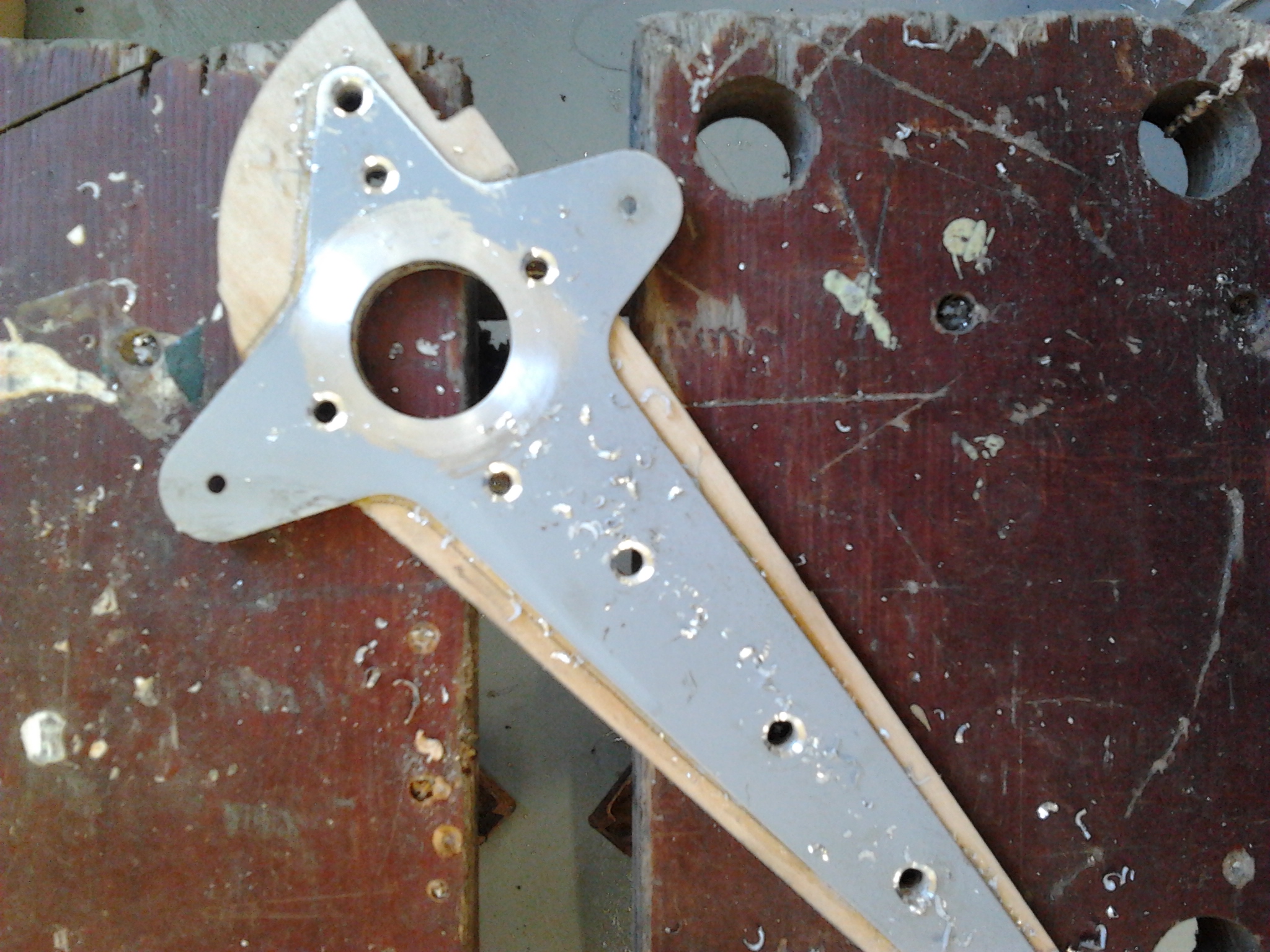
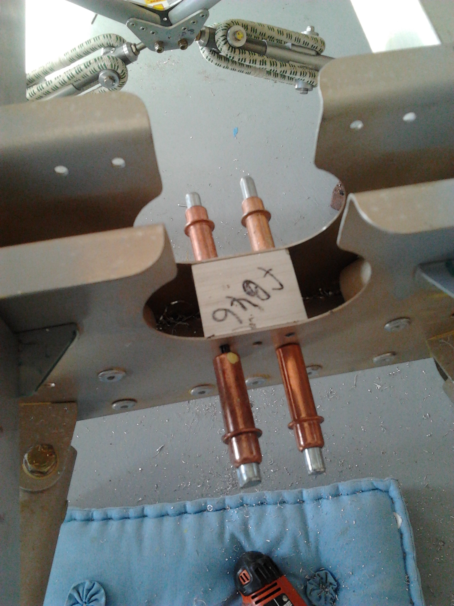
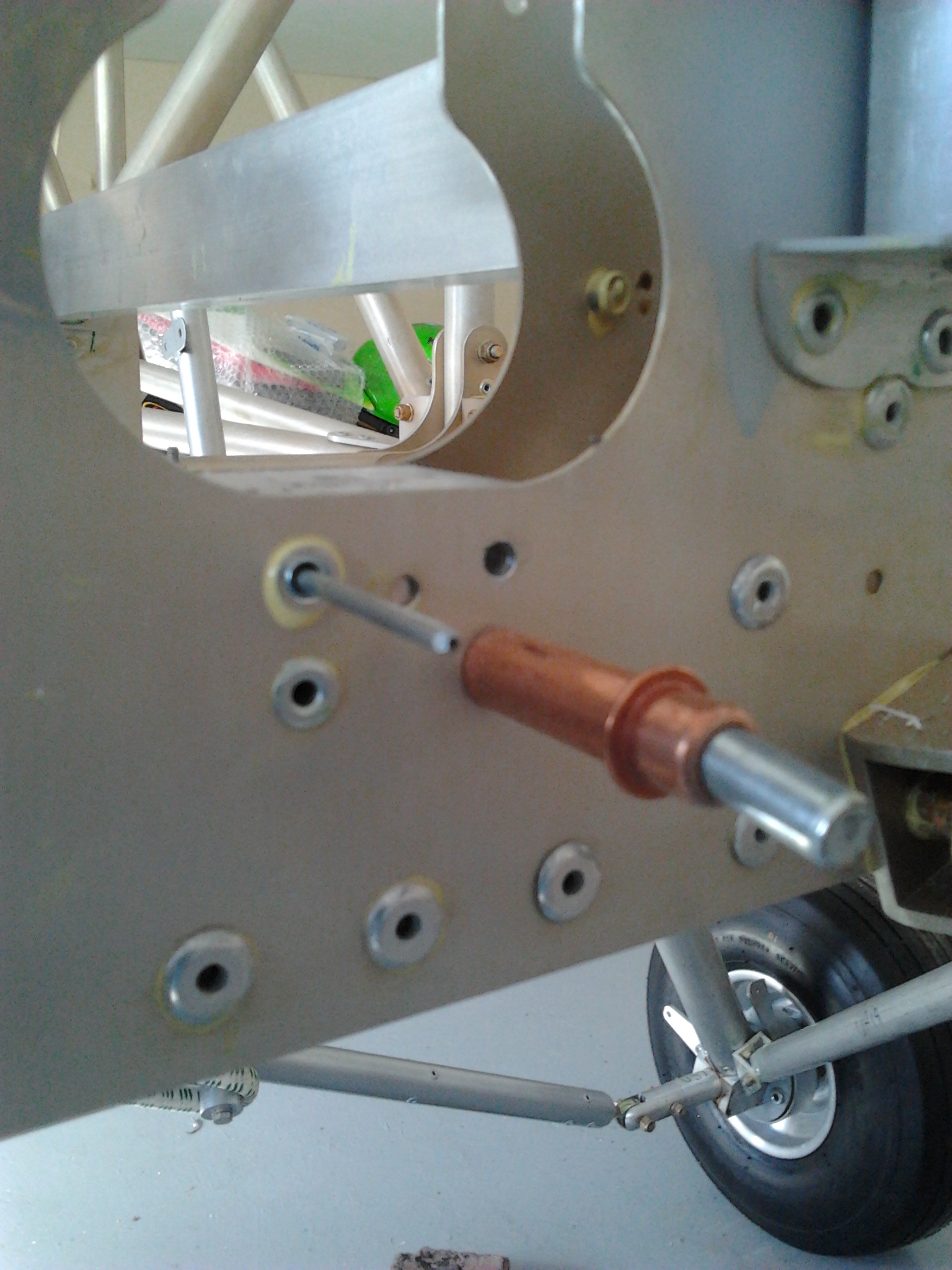
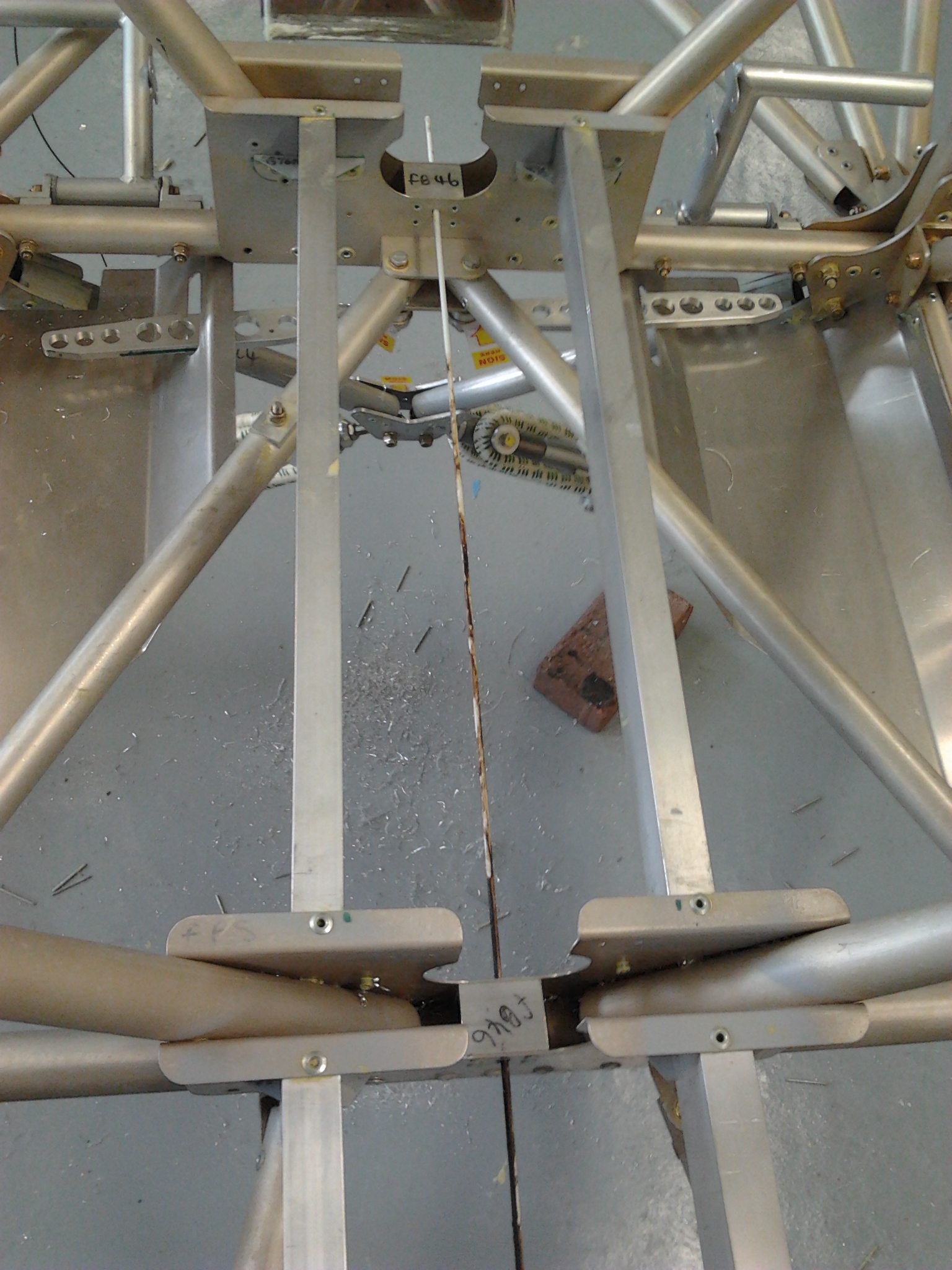
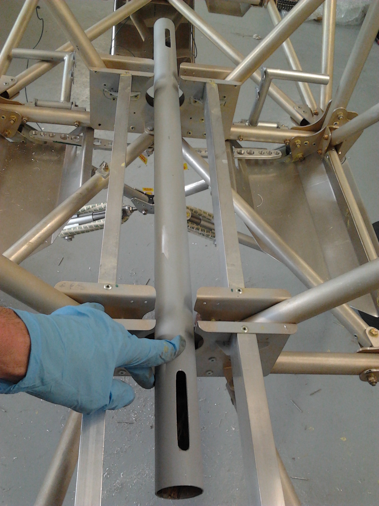
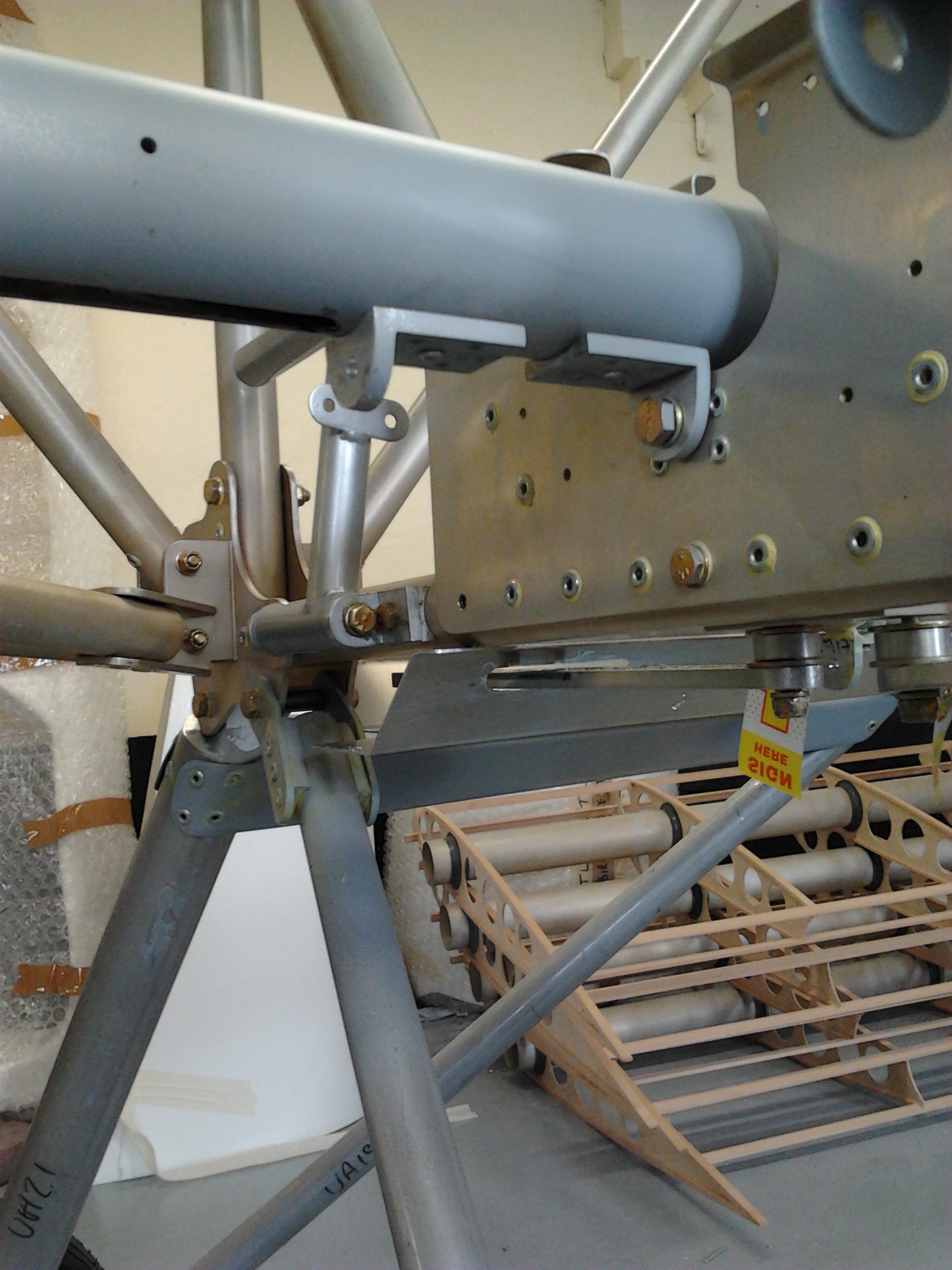
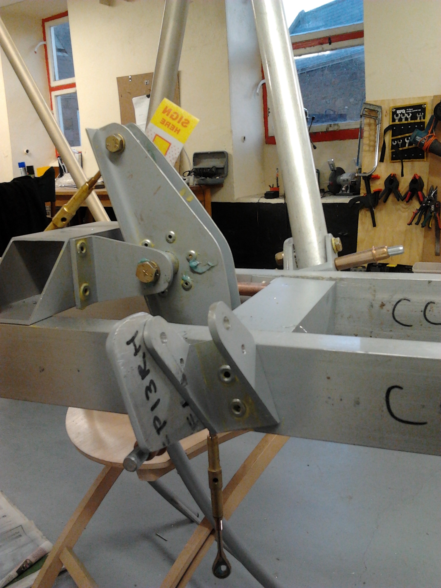
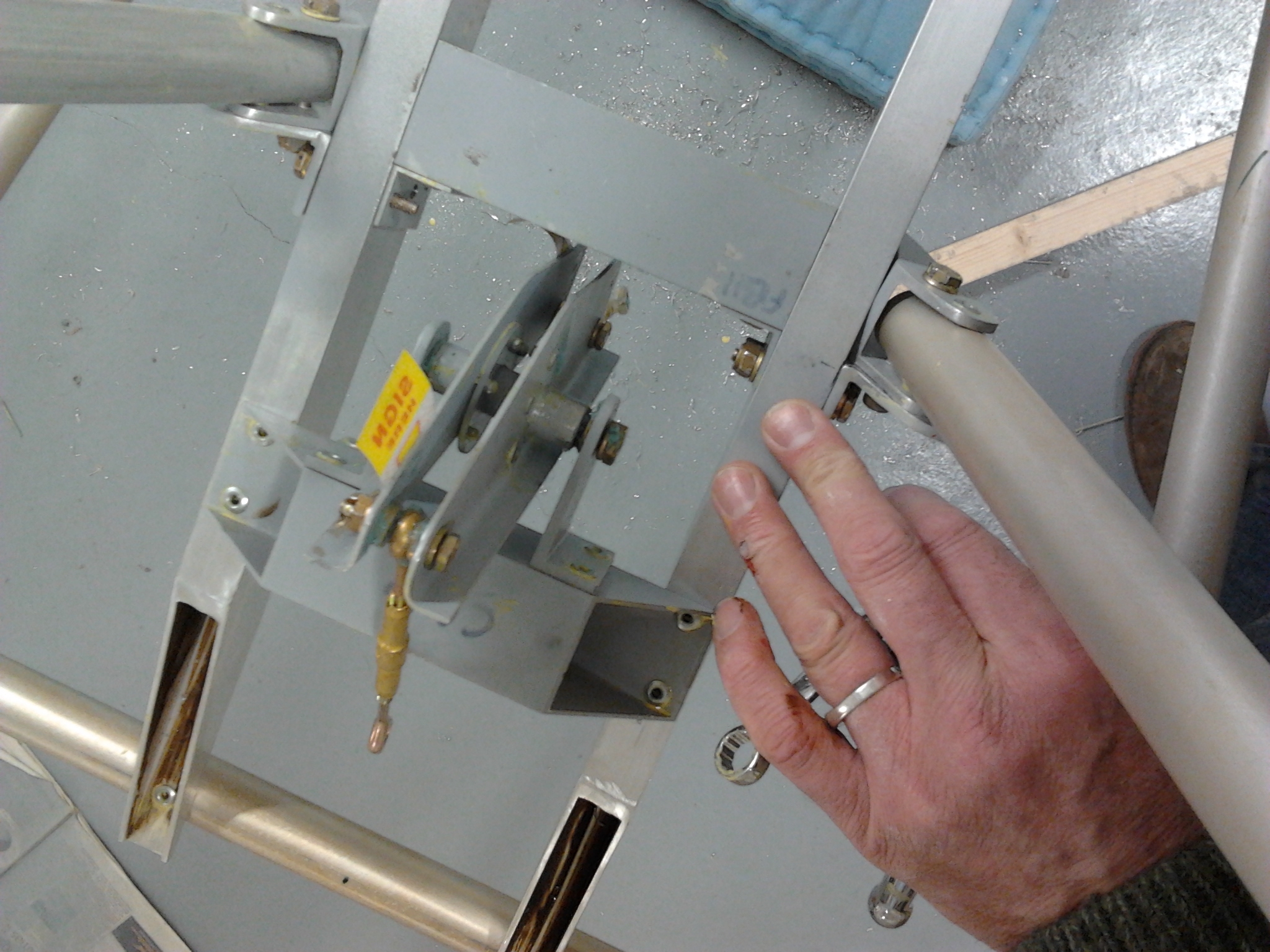
Etch paint duly mixed with its activator and left to stand for 20 minutes. Then applied to all bare metal surfaces that have been added, ie Tail feathers, undercarriage bits etc