Elevators Connected

Elevator cable closed loop 1

Big step forward on Friday evening/night (4th October) .. with the helpof Keith and a lot of his little helpers (children !) we managed to get the Elevators held steady/level, the joystick held centrally and vertically and in neutral, and the first cable secured and clamped before using the large Nicopress tool (many thanks to Channel Island Aero Services CIAS – Bob, Bob, Graham and the team for their continued good natured support !).

After a good couple of hours more of tweaking and adjusting first top, then bottom cables we finally went from a state of far too much down, far too little up and a neutral that would have had you heading earthwards at more than the approach into City airport !! to a state of great celebration as it slowly moved to 20 degrees up, 20 degrees down and a neutral that was spot on !

The turnbuckles just need a couple of turns to bring them in line with the MAX 3 exposed thread limit noted on the plans.

Aileron – Test align

Having started with lower left and lower right (driving) ailerons I have now got the ribs glued to leading and trailing edges and now started fibreglassing to aileron spar.

The centre two ribs are close together and make up the primary hinge point which is underslung.

This aileron is then offered repeatedly (lost track of how many 100’s of times I have done this !) to make sure it sits squarly and centrally in the wing slot.

Stbd aileron test

Rigging Tail

Sam riggingFerrule 2Last night was a fun packed session of tightening all the rigging at the tail. The Tail is supported by 8 rigging cables. Two on top at each side (supporting Fin to Tailplane) and two underneath at each side (tailplane to body)

The cables had been pre prepared, swaged at one end and each tang packed with 3-4 washers so that you have some adjustment once you have swaged the other end of the cable to length.
To assist in this process you have to place 5Kg of weights on the tips, check for level and true all the time and get the cables to have a dull twang when completed.
As the manual points out the effect of bringing these all up to tension gives you a fully closed loop effect. So tightening one affects all the others.

An evening of depression and elation followed as it all looked good, then went apparently slack, then went taught again as we successively did opposite support wires.
Rigging taught
Great job in the end as the whole thing began to settle as washers were removed to just tighten it all up.

First Inspection ….

Today was my first proper inspection. Bob duly popped around on what was a fairly traumatic day in Jersey with an early morning crash of a Cessna into the bay in St Ouen’s in thick (typical) Jersey fog.

The 14 or so checkpoints outstanding could be reduced by up to 3 perhaps 4 !!

Bob checked

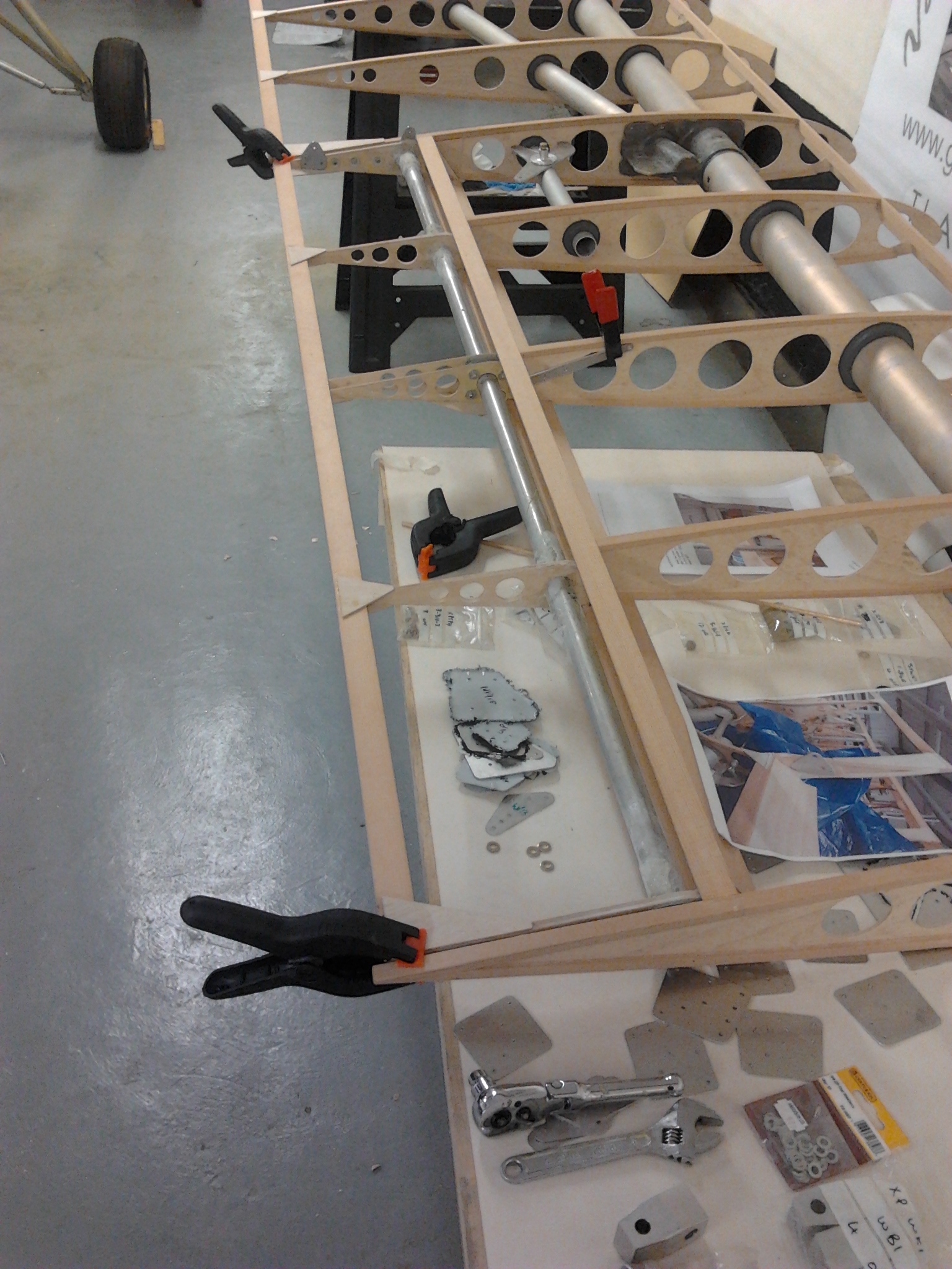
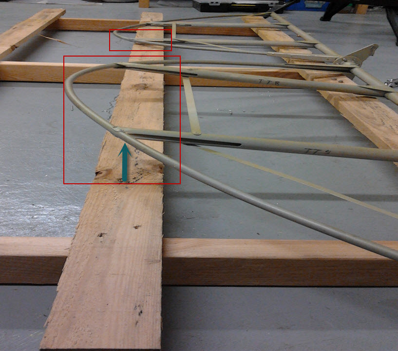
  • Elevator – fittings, finish, accuracy
  • Rudder – ditto
  • Tailplane – ditto

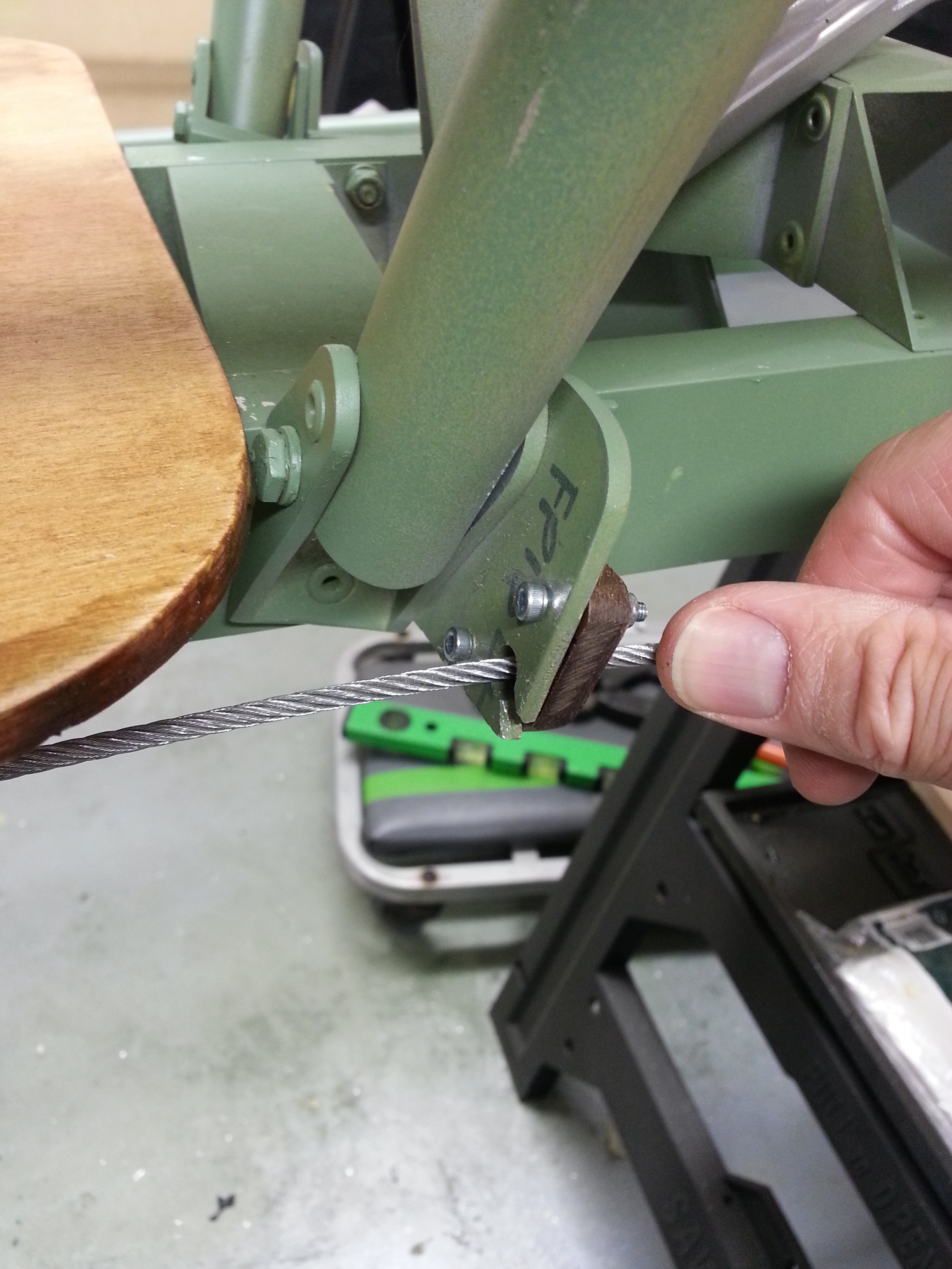
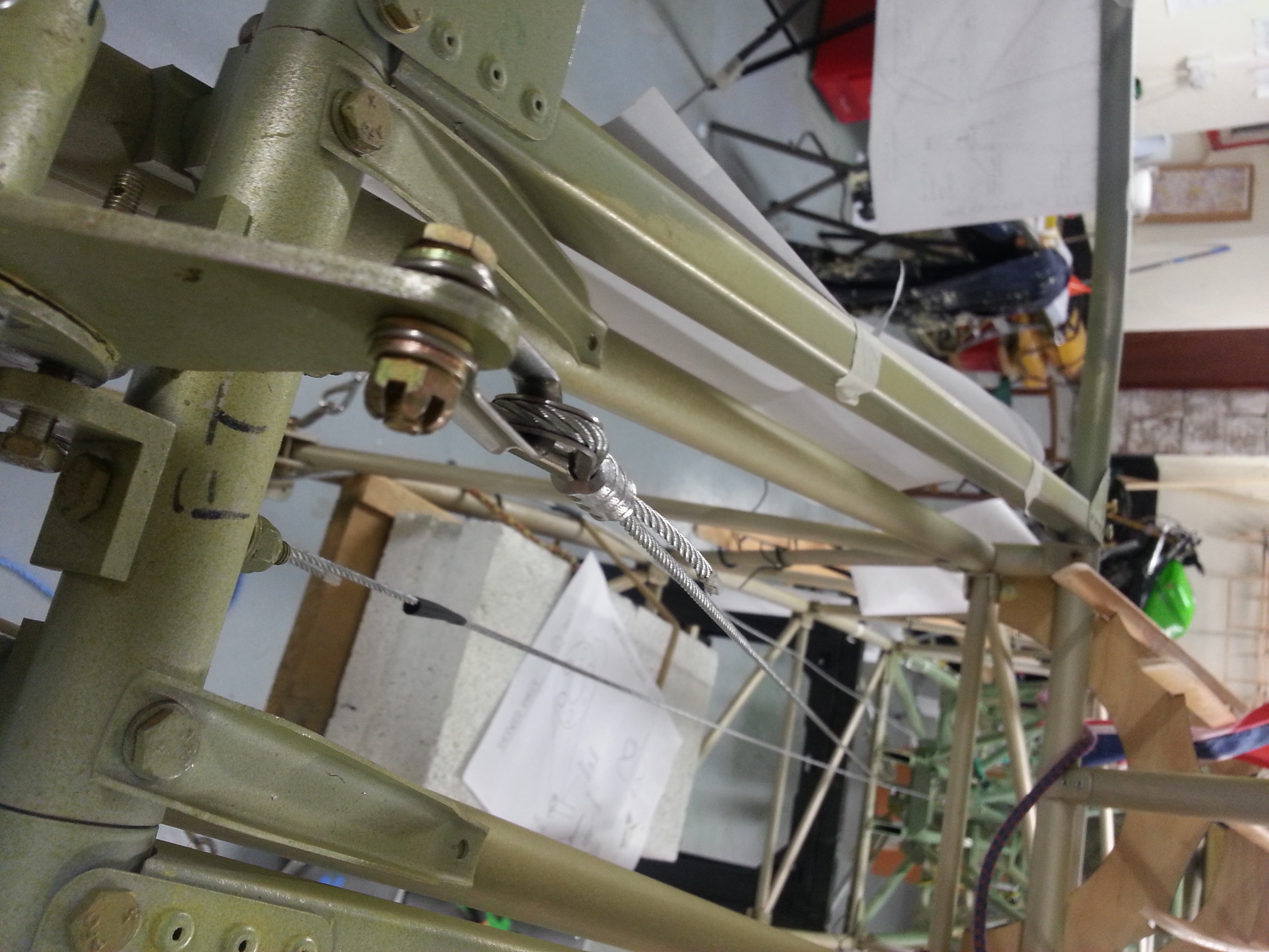
All checked out OK with a couple of comments and advice. One, which applies to all fittings, at least 2 threads should be showing beyond nylocs – my currently untightened bolts for the rigging will do this once tension is taken up and excess washers removed.

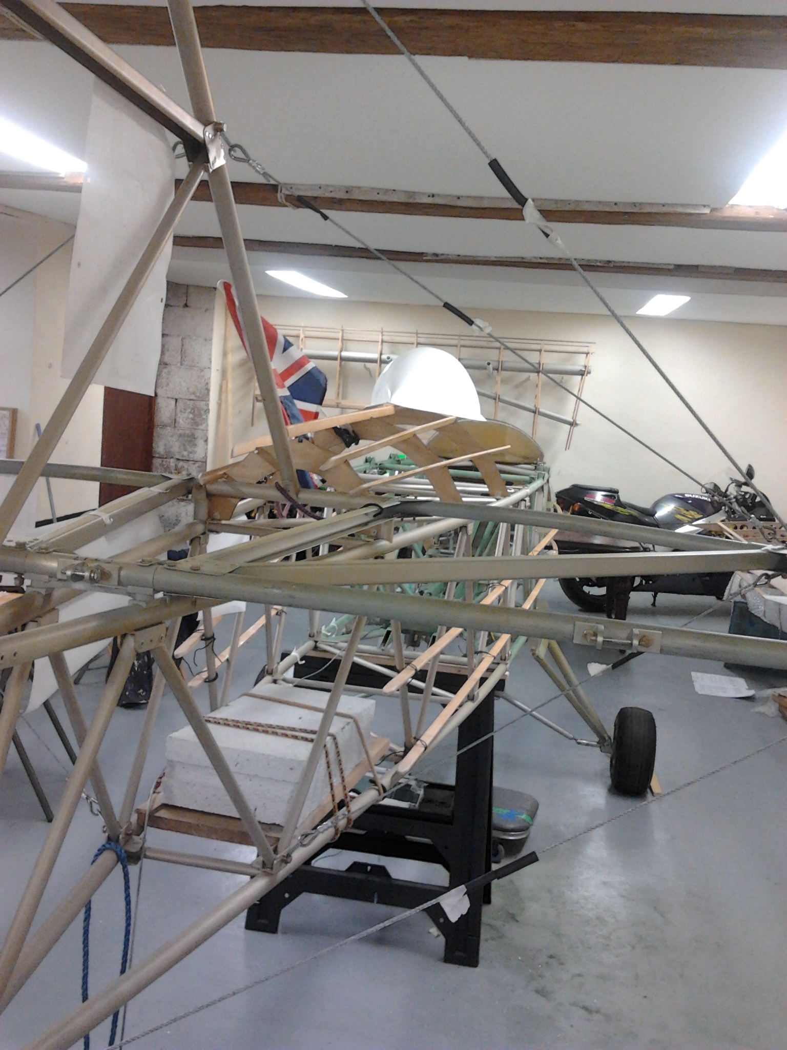
Bob also noted that there was no counter balance weight on the rudder, noting that some similar models and Pipers etc have a weight in the top of the rudder in the forward overhang as this adds stability and potentially prevents rudder flutter.

Double checked with Paul at TLAC and this wont be needed but good to check and get advice and input.

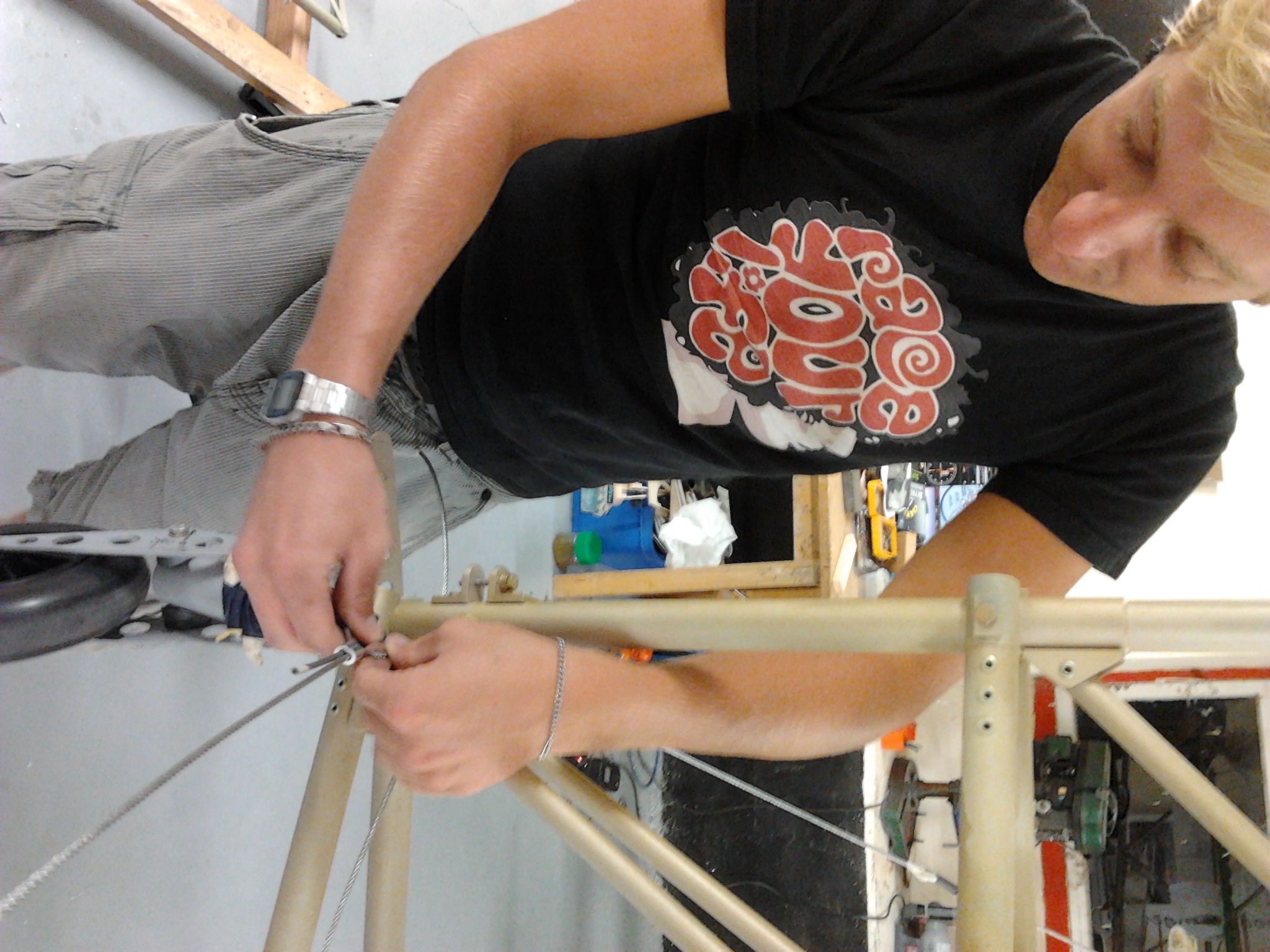
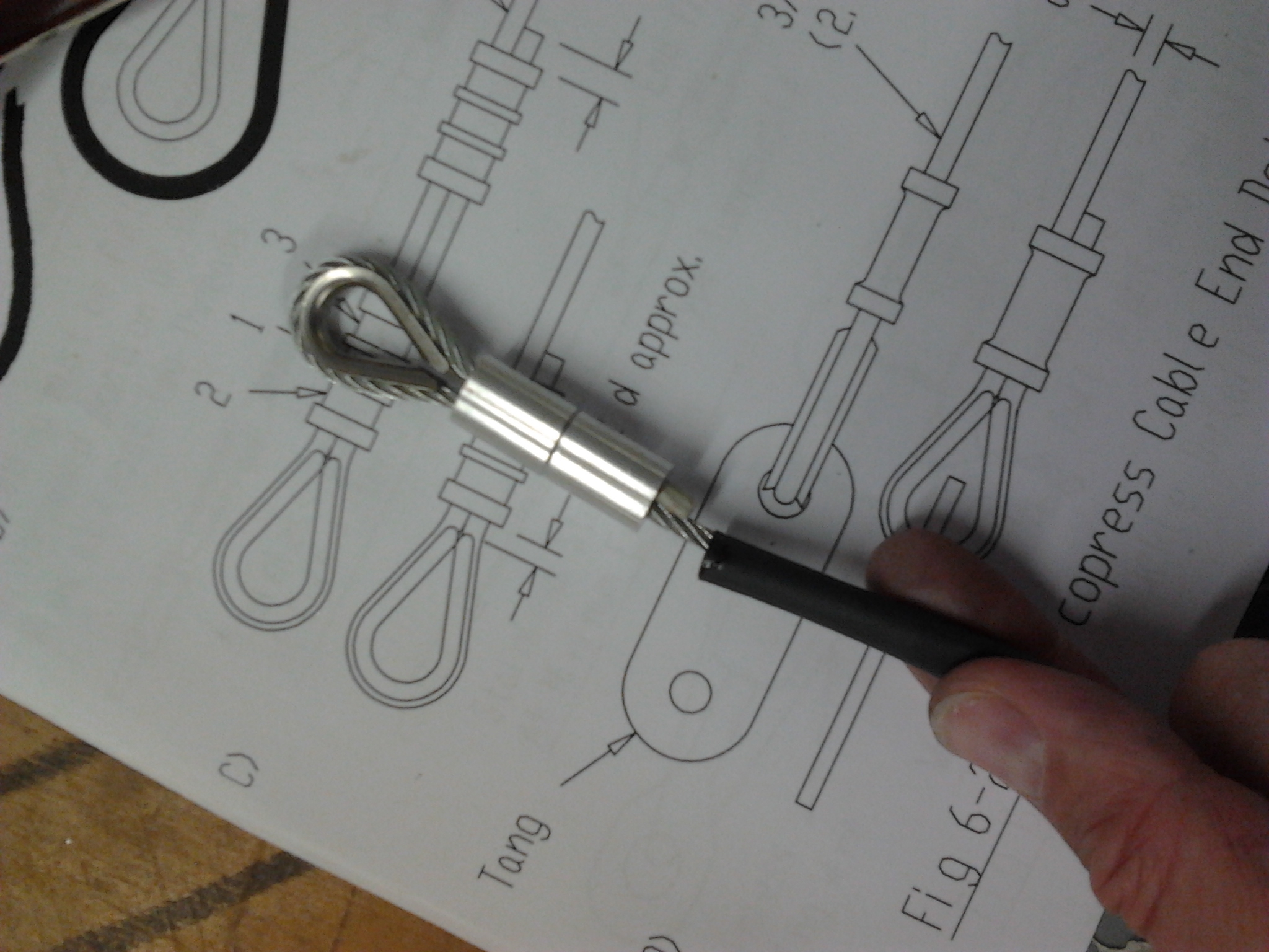
Now I can crack on with rigging and cabling and top decking.

Thoughts are with family and friends of N289CW

Elevators levelled and riveted

Tail not levelHaving removed the elevators to allow the tail to be rigged it is an opportunity to place them on a flat surcae and drill the centre connecting horns through once the LEFT and RIGHT have been levelled with each other AND the elevator horn has been set to the required 60 degree rake forward.

This would have been pretty hard to do whilst they were fitted to the aircraft due to incidence on tailplane and all bits generally getting in the way .. so much easier laid flat on the floor with a large spirit level
tail level

HIGHLIGHT – Elevator Intermediate Horn connected

Finally got around to working out the bushing and support for nthe rear intermediate elevator horn. A small 1/4″ washer is filed to provide an ‘internal’ facing chamfered edge to but against the industrial ball swivel. This allows the ball head a greater degree of movement rather than coming up agsinst the albeit very smaquare edge of a 1mm thin washer.

This meant I could trim the trailing intermediate rod – that is connected inside the torque tube to the rear (Pilot) joystick.  Once measured and checked 5 times in situ (DO NOT want to cut this one wrong !) then the whole torue tube, control joysticks and training connecting rod are removed from the aircraft to allow drilling and riveting of the end connector. Tube had all been pre coated internally with Waxoyl to prevent any internal rusting.

Once drilled and riveted the whole lot can go back in the ‘plane and a trial connection to the elevator intermediate horn..


FANTASTIC to see a stick pulled back move both sticks in unison (obviously !) and then the elevator horn move through the pre requisite angle and no catching ….

Just the cables now to the rear elevator horn .. remember they have turnbuckles AND crossover towards the tail to make sure Back on the stick equals UP elevator !!

Aileron leading edge support block

Blasa  blocks are provided to be trimmed and cut to fit between the ribs – mounted on top of the spar (using epoxy) to then be shaped to form a mounting surface for the top leading edge 0.8mm ply

The blocks are first pre shaped to provide a ‘mated’ key to the top of the spar. A 1″ round dolly is used with sandpaper wrapped around to provide a suitable curved channel in the bottom of the balsa block.


Once dried these can then be shaped on top using a larger hardwood dolly to overlay two ribs so that you sand down evenly to get a flat surface.

The 0.8mm ply is then epoxied to the top if the block and, once dry, Aerolite glue is used to secure to the top of the ribs and the leading edge beech.

Aileron – Firbeglassing ribs in position

Not a job I had looked forward to … hate fibreglassing at the best of times … not nice stuff to work with !

Cut 20 mm wide strips by 60mm of 600g (2 oz) mat (CSM) and this makes it more manageable when trying to get it over and around the compound curve of the aileron spar. These strips were overlaid but still managed to ping up occasionally in the drying process !

The small pointed sander came in handy to neaten  off  the usual spikes of strand that you get with this process … how anyone ever constructs major pieces with this stuff is beyond me

The finished sanded joints dont look too bad and have ceratainly made the whole thing feel very robust.

Aileron – Leading edge – Scarfe joint

The leading edge ply for the aileron leading edge is 0.8mm so quite plyable … only problem is that it is just too short for the length of the quite large ailerons … this means making a scarfe joint to butt two pieces of ply together to make up the length.


Having read up on the internet exactly what a scarfe joint is … basically a layered joint to ‘blend’ one piece over the other. The internet was useful in that it gave advice on how your new joint was squared up … ie sanding using a hard block on the edge of a solid surface … then checking that the various layers (3 in this case) reveal in a straight line … then you know your chamfer is square


First Inspection

Been getting the plane and workshop ready for the first inspection. All the relevant build digrams have been stuck to the airframe in the proper place to make checking easier.

Fingers crossed as I cant continue with other cabling and top deck bits until that is approved.

Blog at WordPress.com.

Up ↑