Spider off and bolts visible

Cut off a few cable ties to free some of the cables that were tied securely to the spider …

Labelled some of the cables for later re join

Slackened the 4 bolts securing the spider to the backplate … capturing the small 8mm nuts at the front end and their washers so they can be returned to the same position

Some of the supporting plinths stayed in position so easing the spider out ‘square’ was tricky … taking care not to pressure the alternator stators

The port mag decided to stay on its plinth so removed it in situ and can separate away from the engine bay. Having released the alternator pair of charging cables slipped through the centre hole and the spider could be lifted away. Boy, the magnets are strong and take some pull to get the unit out.

Wih the stator out .. you can now, finally see the 6 x 5/16 bolts that secure the flywheel in position

Now the job of locating a good quality Allen socket head to get good purchase on these … after considering whether to try the pencil flame idea of pre heating

100 hour check on the way

Pre planning the 100 hour engine check …

Its done just under 95 hours … at very varied power use .. which the manufacturers recommend .. ie don’t drone around at the same RPM hour after hour as the pistons glaze the bores …

(Update .. just cross checked my log book and engine run hours with my Hobbs entry and Hobbs is 99.25 … so time to stop and do this…. New bolts arrived 26th Jan 2021)

This has been a great workhorse .. hauling lots of small, medium and Large ! People around .. and also purring around at 5,000’ on very low RPM .. then nice fast turns with smoke and eager passengers who like to see the world on its edge ..keeling around on a wingtip ..

I’ve religiously changed the oil every 25 hours …after the first 25 .. you can go to 50 hours between changes but it’s so cheap AND a really easy way to make sure nothing is going awry over time …

Anyway … it’s 99 hours now .. so time to plan a usual oil and plug change but also … there is a service bulletin that states you should check and change the 5 bolts that hold the flywheel in place.
The great session I had at Skycraft last year showed how closely clustered these bolts are … they bolt directly into the rear face of the drive shaft.

They need initial checking to see if any have worked loose before they are all replaced with improved design and improved Nordloc washers.

In the early days, Jabiru had problems with these earlier bolts sometimes failing. A bolt failing on a flywheel as you might imagine pretty quickly adds strain to those remaining and your flywheel starts to think about other trajectories !

Not sure who it was … but years of clever research was published recently … and the LAA published in their regular magazine … Bizarrely.. it turns out that the recommended cruise RPM of around 2,700 RPM sets up harmonics in the assembly that is detrimental to these bolts !

THIS replacement is purely precautionary … but wise …

Location of flywheel bolts and inspection hole
Bolts fitting into tail end of drive shaft
Nordloc washers under NEW bolts

update 23 Jan 2021

Had a look at the back end of the engine today .. to see what the back of the ‘spider’ looked like .. turns out I can’t see the bolts .. but see a splined end .. so guess it’s a spider off and then release the splines mount ..

Spider removed to reveal alternator stators
Splined centre module … not sure what the spline offers ? But this is where the bolts are


I asked Dave Almey from Skycraft what the spine end was for … apparently it’s so that you can add a drive shaft to drive a vacuum .. if you use vacuum instruments … learn all the time) .. thanks v much for quick response Dave

This excerpt from the LAA magazine mentions the detail around removing previous bolts … that were secured with Loctite … and recommends pre heating to break that Loctite … vs … with Nordloc washers NOT to use Loctite PLUS differing torque settings

Will be interesting to see how you can “apply heat to the thread and not the head of the bolt” when zero thread is actually visible … it ALL being in the body of the drive shaft 😊

At last … after searching and sub referencing different Jabiru docs I have located the different torque settings associated with Nordloc washer on the cap screws … bolts .. for the flywheel …. 39nm

Another late evening freezing flight and 2 close circuits to finish

Great flying conditions.. cold .. but clear .. and some moody clouds thrown in …

Problem at the threshold just before take off … finally full and free movement check and spotted a loose inspection disc over my head … quick call to tower .. shut down at the hold .. unstrap .. lift out of seat .. slide panel back into position and restart .. 60 seconds … ready to go …

Thanks for the photo Sarah
So .. at 07:41 in this video … I look up and see a slightly loose inspection panel ….about 30 seconds later – call ATC and inform shutdown .. to push into place … then restart 60 seconds later
A figure of 8 in the sky for Clair M

Finish off the oil before landing …

2 final circuits – close Bad weather – nice to fish – with feet and hands like blocks of ice !
Close left base 26 into the setting sun
Thanks for the photo Greg

Investigate vs leave alone

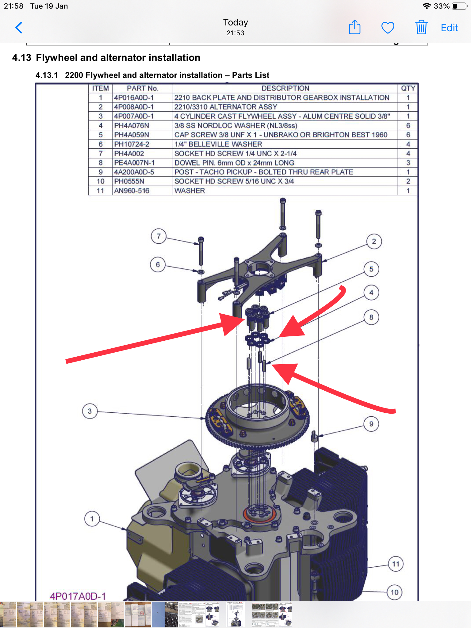
What do they say about not fiddling…

In my continued attempt to pinpoint the source of my random non rhythmic radio crackle I spent a good couple of hours before Christmas and, in the process removed and fully checked both magneto switches …

I had to cut away some of the very hard sheathing around one of the spades on each Mag switch.. to find that they were OK but probably could benefit from a re crimp with my later better quality crimps

I replaced the 2 switches which are a very tight fit on the right hand side cockpit coving and, conveniently right next to the push button starter… RIGHT next to it

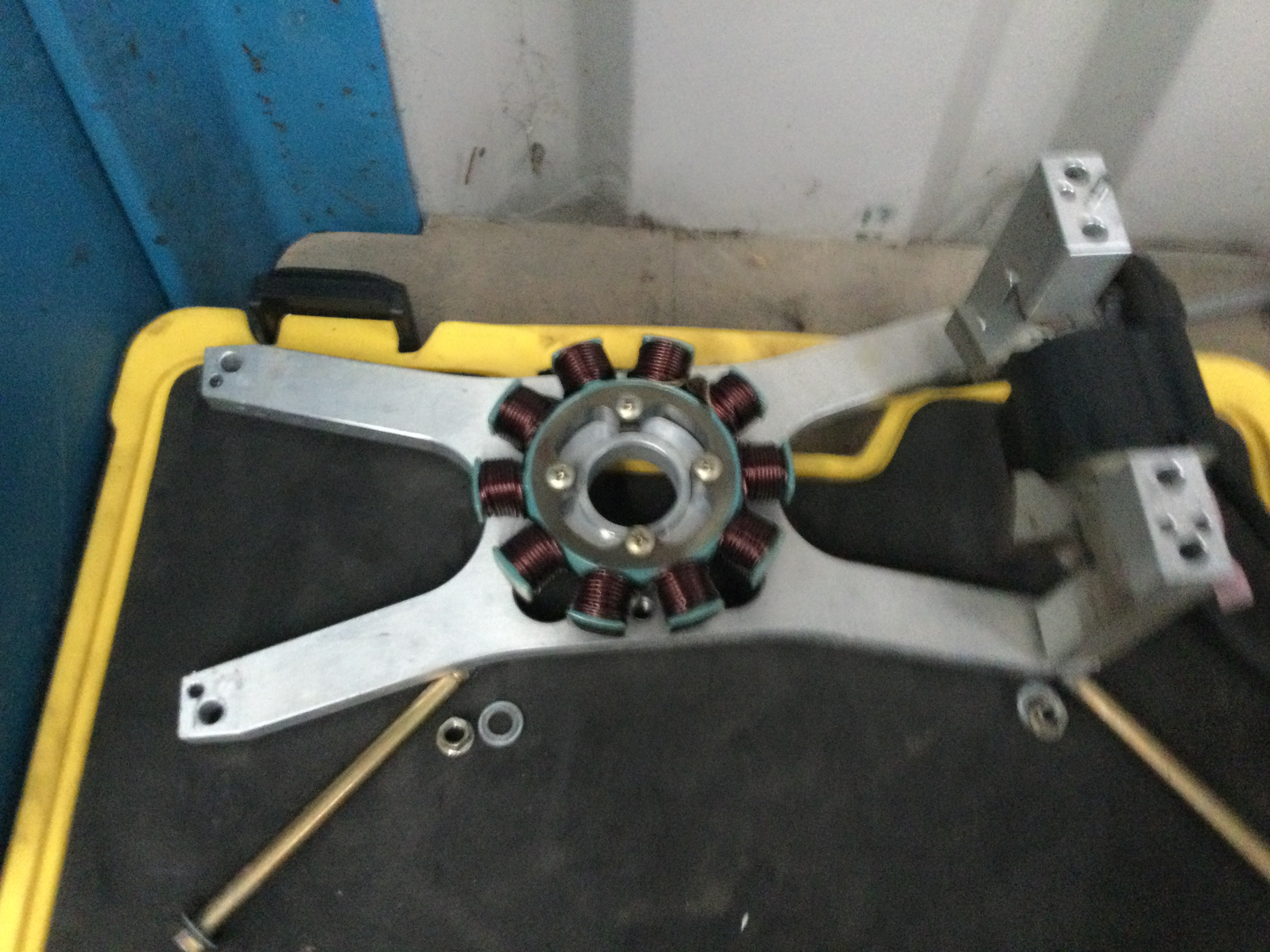
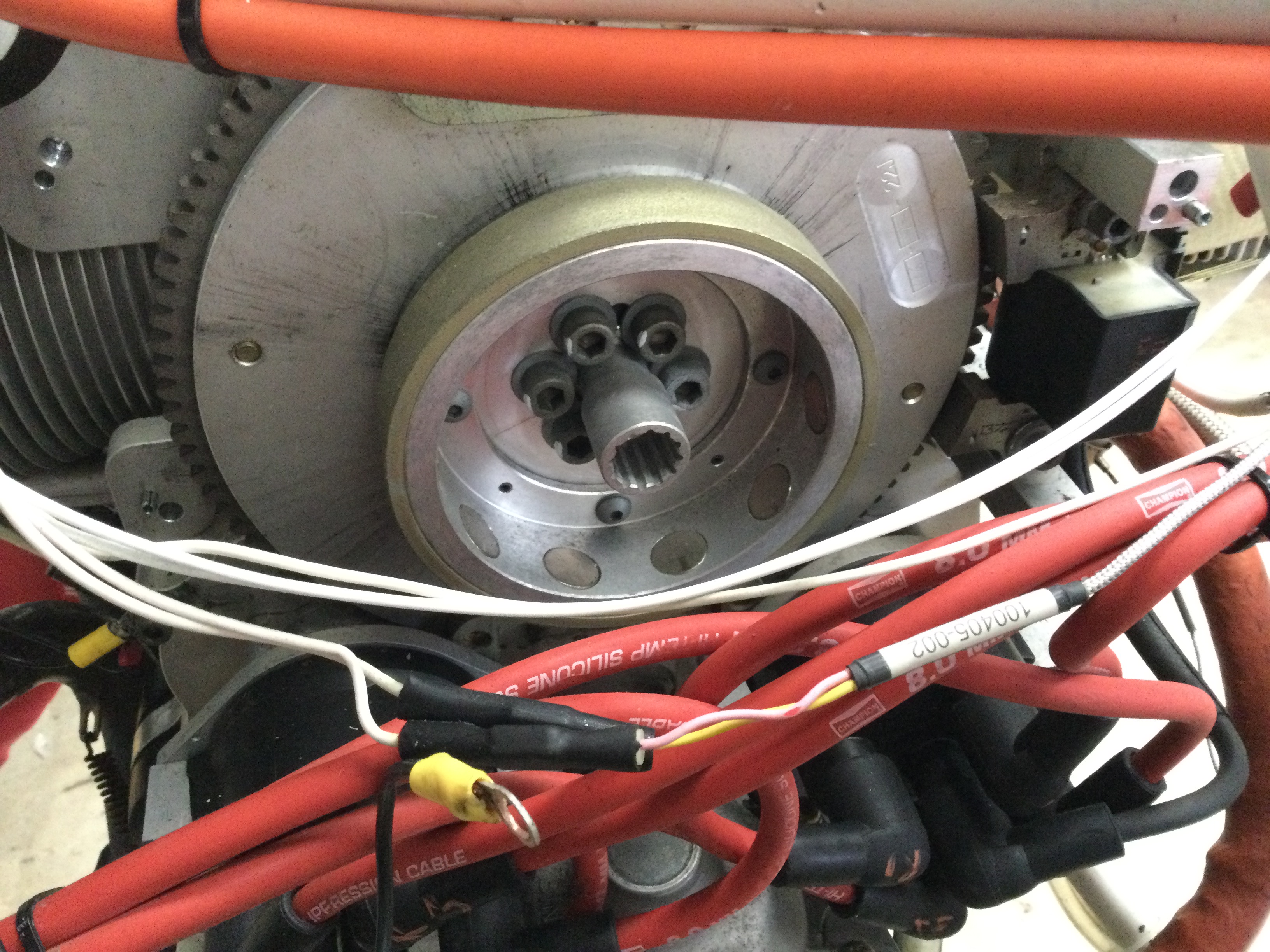
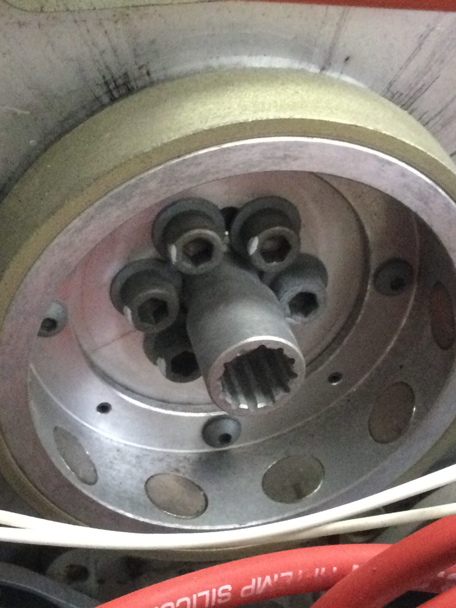
The last thing I checked was the spade connector on the Left and Right magentos in the engine bay. These too were hard sheathed and I found a bad crimp so cut off the spade …

Replacing it today and I hit problems … at first it simply wouldn’t start .. and ALWAYS start first touch … then it fired and turning the left mag off killed the engine completely….

After removing the cowl to re check the new spade .. nothing wrong there … so removed the two mag switches again … it looked like the left one could have touched the rear of the starter button … but couldn’t be sure

Then the starter simply wouldn’t start … and seemed to have lost all power .. I looked at this for a while as I wasn’t sure what was going on here … so .. step at a time .. try the alternate power source .. and pop … the first time I’ve seen one of the aircraft fuses pop out …

So .. this means its something around starter button …

It then dawned on me that if I had managed to get the rear of the mag switch touching the rear of the starter .. then a fuse would most likely pop and the failure of the primary master switch had no doubt blown the car style in line fuse 10 minutes before!

Removed both mags and let them dangle whilst pushing the pop alternate fuse back in and press start … Bingo … absolutely fine … and even got an improved left mag drop … so confirming the bad spade crimp I started to fix with …

It was now too late to fly so put her away all rigged for another day 😉

response from Nigel Snell .. I have pasted it in here as it was really descriptive but couldn’t see it in the blog

Hi David
Have you checked that your shielding on the wiring for comms and radio leads are not earthing out to the airframe, if that happens, you will create what is called a ‘ground loop’, which will result in crackling or buzzing.
The terminals, where they meet a metallic panel need to be isolated by fibre washers, likewise the cable shielding needs to be prevented from earthing out along its length.
Random crackling normally occurs when a flexible, or moveable cable is grounding out due to random contact.
Loose pins in block connectors can also create the same effect, or a loose shielding connection.
Hope this helps.
Kind Regards
Nigel

Hi David
Just ‘re read your reply, do you mean the comms leads are earthed to the airframe individually by small screws ?.
The comms leads shielding should only be earthed through the Radio earth back to the battery to complete the circuit, if it is earthed at more than one point, I.e. additional earthing points, it will create a ground (Earth) loop, if the wiring distance is short length, then it might not matter, but at times of high current draw, it can result in buzzing or crackling.
To explain electrically what happens is very complicated. About the simplest way I can describe it, is that normally the earth (Return), will take the least line of resistance.
When you initially press the comms switch, there will be a spike in flow, then the current will stabilise, this can sometimes be heard as a pop as you press the switch, which would indicate that the inline capacitor is not large enough to absorb the initial spike.
With regards the earth ground loop, because it will at some point, have electrons flowing along it in times of high current flow through the airframe, it back tracks up the earth lead, activating the speaker, hence the crackling.
Now, let’s assume that one, or more of the individual earthing points have corroded, and now the current has further to travel along the completed circuit.
When the earth routes were short, it didn’t matter, because the flow of electrons had completed their return to the battery as you released the switch.
With a much longer path to take, then, as you release the switch, there are still electrons trapped in the circuit, so the next time you press the switch, the trapped electrons flow again, but they want to take the least line of resistance, if that path is actually backwards to the speaker, so be it, the speaker is now getting a feed from both sides, so the speaker will alternate very rapidly between live and earth, the frequency will determine whether it’s a hum, buzz or crackle.
I hope I’ve explained it reasonably well, but, like I said, it is very complicated, and I’ve missed out a he’ll of a lot.
My dad was an electronics engineer before he became a University lecturer, so it’s not really my field.
Sadly, he’s long gone, but I know he would have been more than happy to solve it for you.
I do hope this helps.
Kind Regards
Nigel

Blog at WordPress.com.

Up ↑