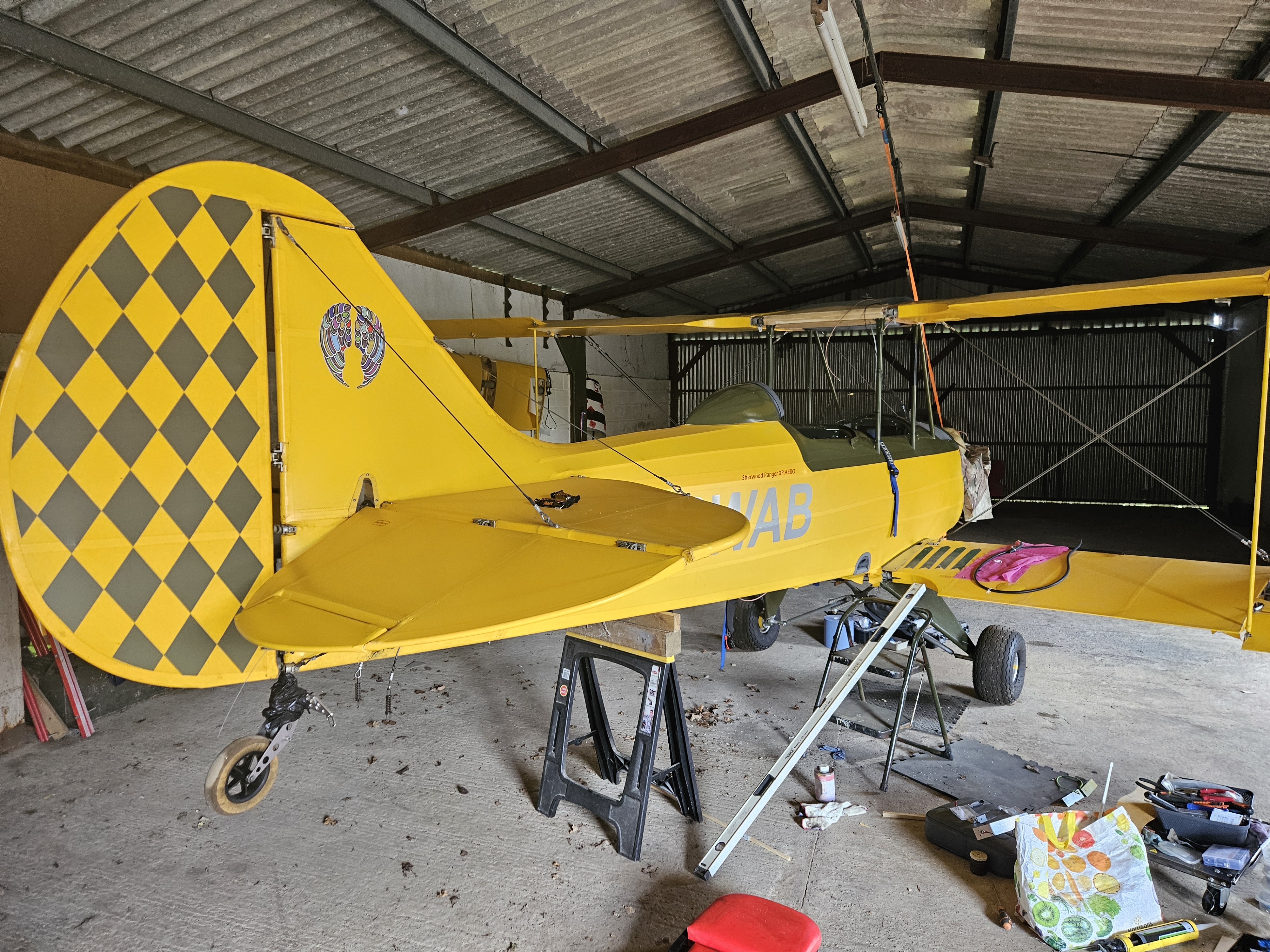
Over the years I’ve re rigged the aircraft a number of times … usually when the wings were on and off between transportation runs between the barn where I built her and the airport. Later trips were easier as I had a trailer and the folding wings were obviously a huge help !
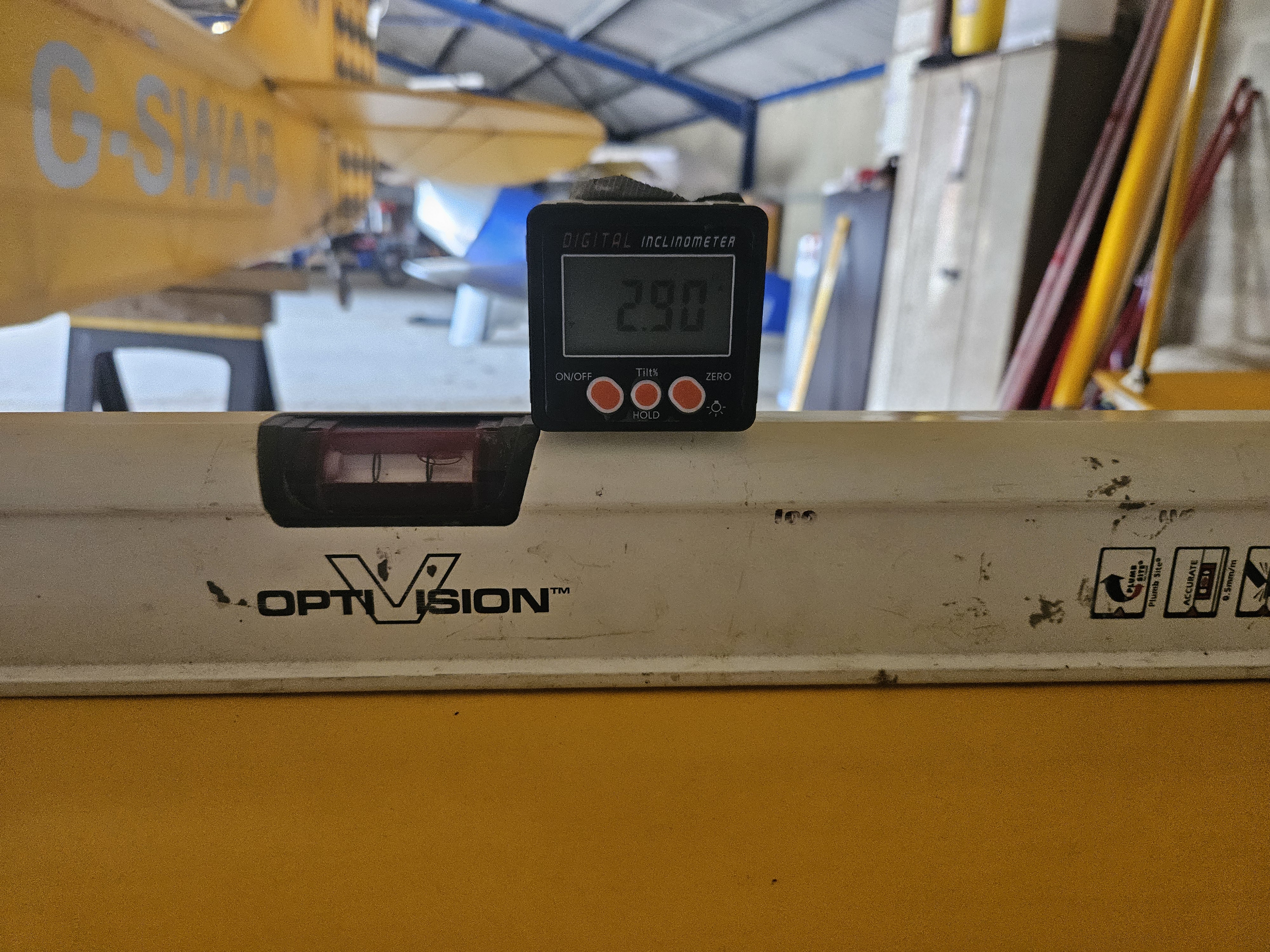
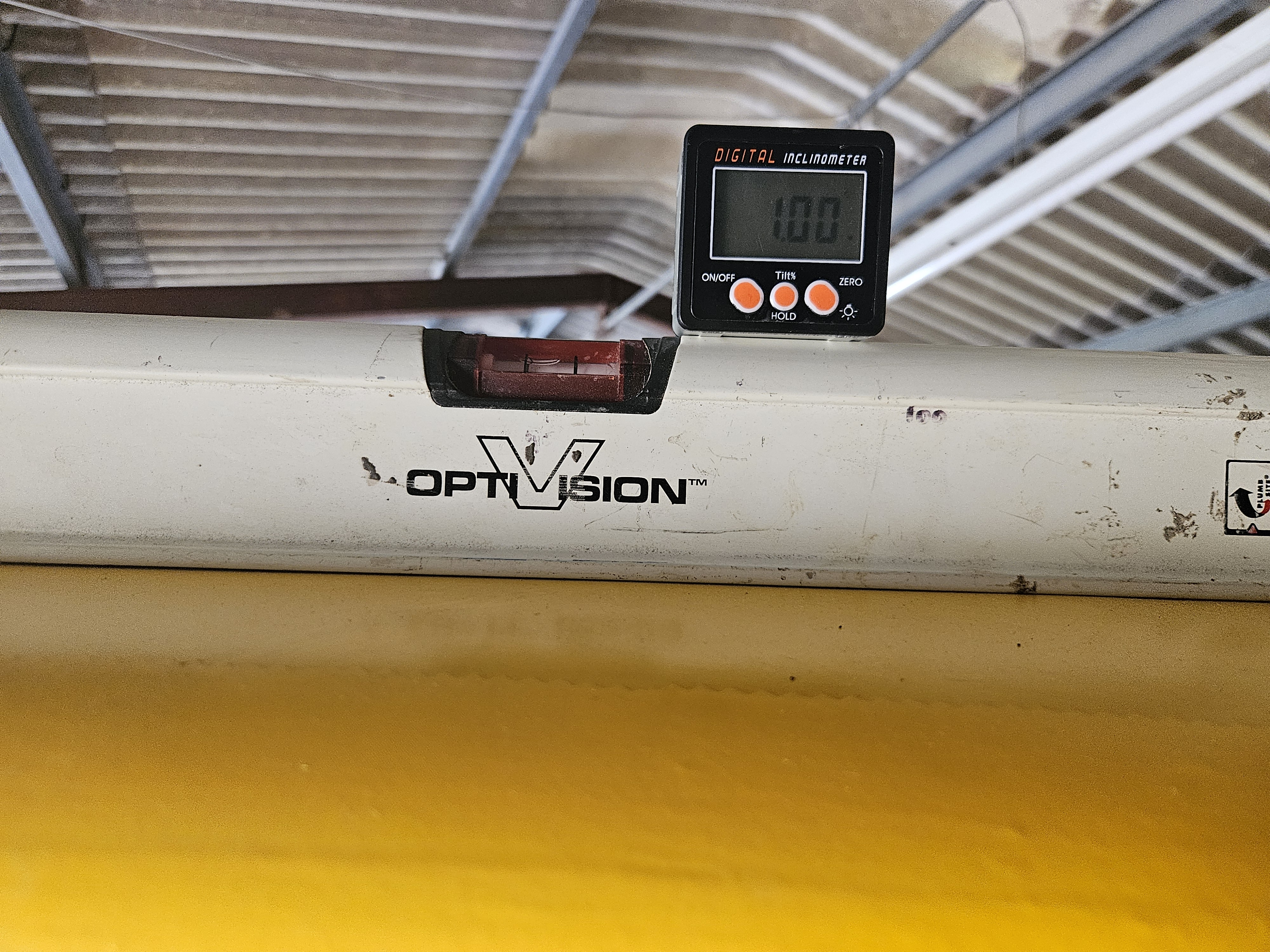
All turnbuckle wire locking removed and each wing with a trestle under to support the (almost) correct angle .. allows you to bring up the turnbuckle tension to achieve the desired angles
Lower wings – 3 degrees
Upper wings – 1 degree
It didn’t take too long before the numbers started aligning and the flying and landing wires started to ping quite nicely
Getting the aircraft straight and level and into ‘flying’ position first is key to ensuring correct settings
Part of the rebuild was a slight modification to the P1 panel.
Although I’ve (technically) not flown IMC in the Ranger ..a couple of unexpected cloudy descents … but flying any reasonable distance can be quite tiring.
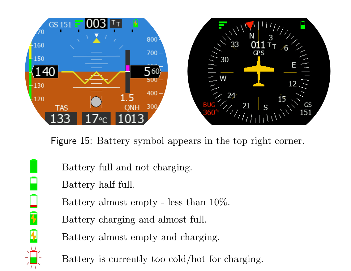
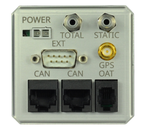
The guages aren’t exactly big or easily visible in an open cockpit with sunlight, so I invested in a multi colour Horis. This provides all the key information in one single very clear instrument.
Unboxing and checking the detail out, it looks very simple to connect. Power, a provided GPS, splitters for the static and pressure tubes and a temperature probe.
Some of the repairs are for bits that weren’t directly caused in the accident.
The port elevator was part that got the material scraped in the hoist recovery…trying to repair the scuffed material was proving a bit tricky so decided to strip and recover. At last the ambient temperatures have risen above freezing so allowing gluing to continue.
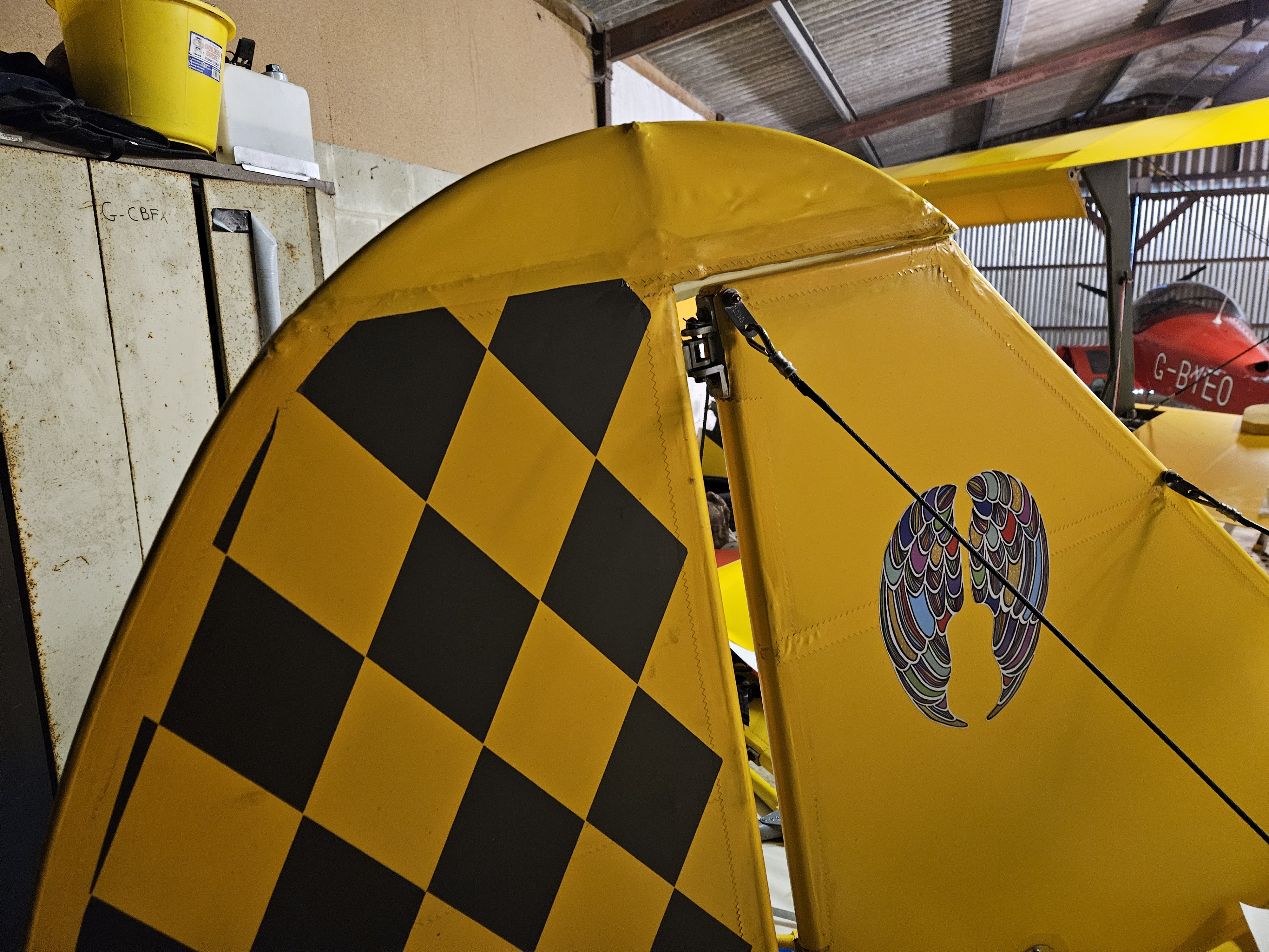
The top of the rudder showed a small crease in the material as it tipped over, so was stripped back to check.
No damage was located so the material was terminated on the top rudder rib and the metal cleaned and prepped for a small repair panel.
It’s a bit of a pain that the diamond pattern in Olive green has now been slightly trimmed ..but may ne able to source a s.all section from the Jersey company that did the original. Remember them saying they couldn’t guarantee the rudder diamond pattern sections wouldn’t peel off at speed ! They have lasted VERY well !❤️
Not too bad ‘pre shrink’ .. will let it all cool and harden and do the other side before applying heat shrinkage to tighten
A busy weekend with home bits but managed to get up to the hangar to start the new setup and position of the radio antenna
The original was smack in the centre of the upper cabane as this was largely an open structure bound by 2 capped ply edge ribs and a centre rib. The whole thing was covered in 1mm Finnish ply and beefed up in the centre which a ply mount for the antenna.
The new upper alloy spare dump tank means that the open structure has gone but the large aero shaped tank is slightly slimmer (at the edges) and so allows space for an offset mount of the new (replaced) antenna .. the other , although probably fine, was bent through 45′ as the aircraft flipped.
I don’t really want the antenna in the body although that could be a logical location..the original, with its upper cabane location and large baco foil style landing plane gave me solid reception up to just short of the Isle of Wight from Jersey at just 2,500 – 3,000′
I’m planning on using the same foil and sandwich idea to get good connectivity
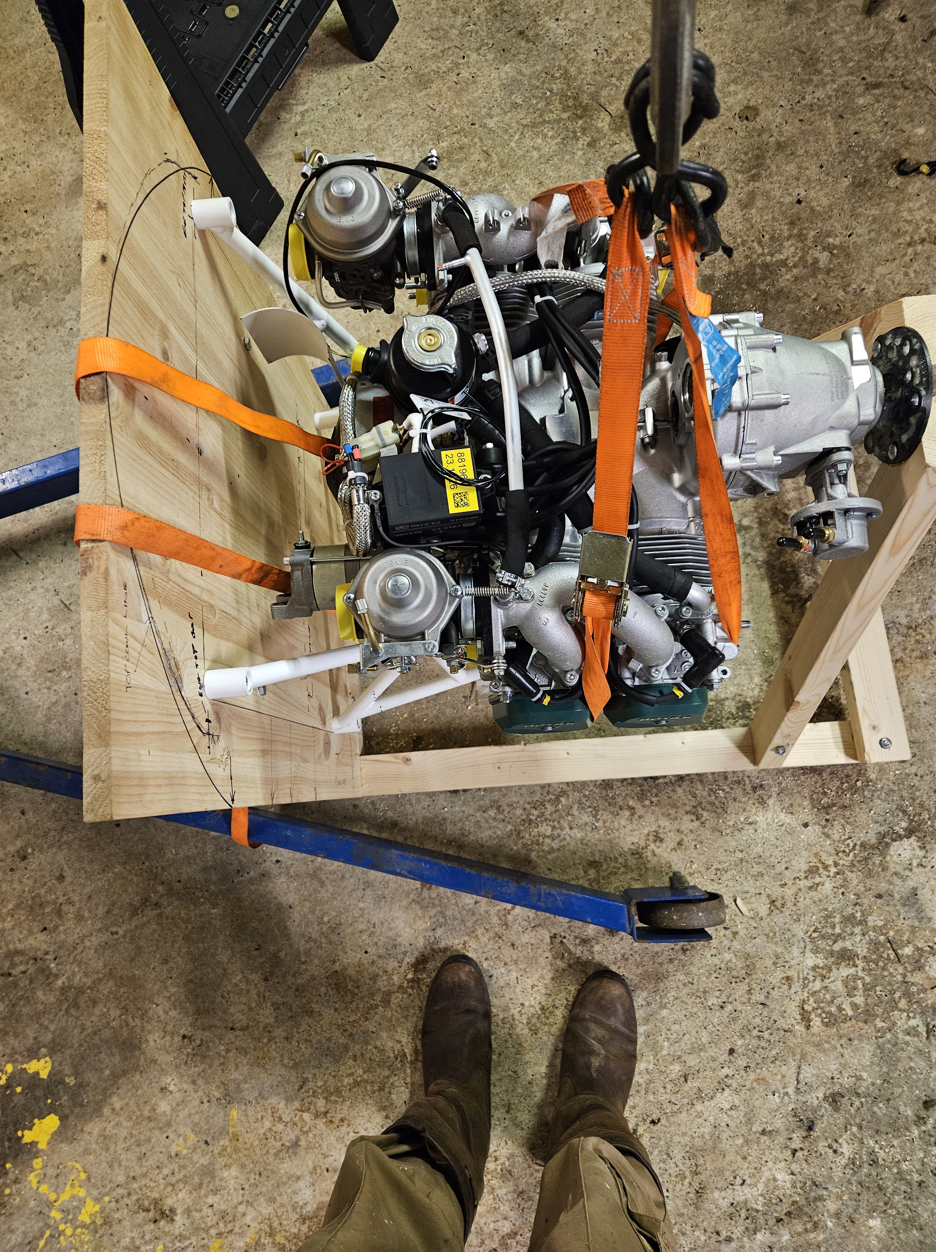
Now that I finally have collated all the parts associated with the new engine fit i can remove it for the exhaust make up.
The local company who are going to be doing this work are an amazing set of engineers who support a whole range of enthusiasts and industry covering classic cars as well as manufacturing incredible items such as Spitfire and Hurricane exhaust stacks !
The assembled parts include:
Exhaust kit (Czech supplied) with straight tubes, O ring angle rings, springs and silencer box
Lightweight oil can that fits very snugly between the rear of the engine and the firewall
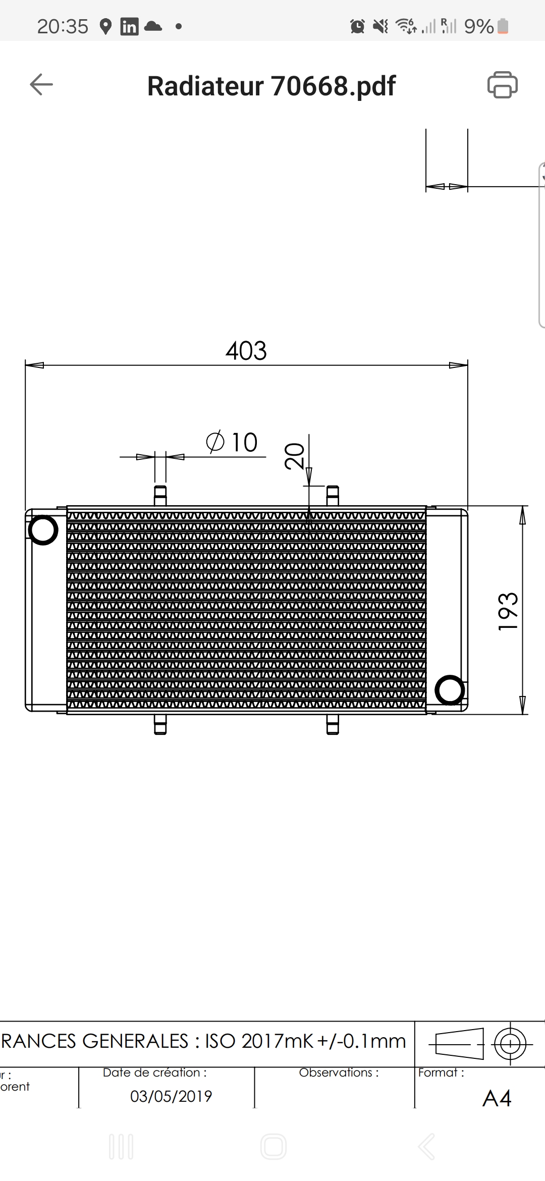
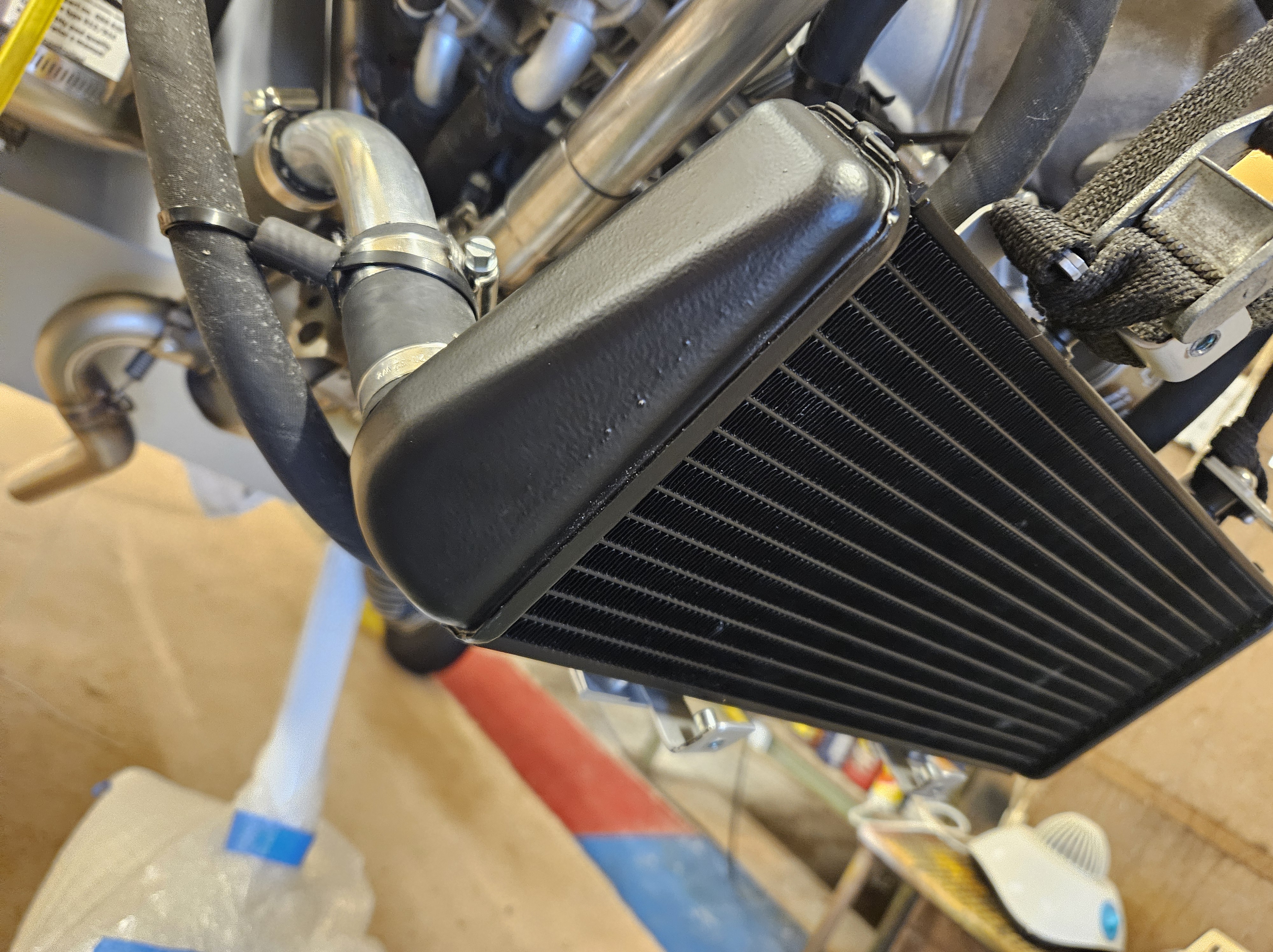
The large (French sourced) water radiator – this will mount on support brackets underslung under the main body of the engine
A much smaller (than previous) oil cooler – actually found someone in UK to supply this ! And the the support arms that will place this right behind the front cowl ‘mouth’ intake
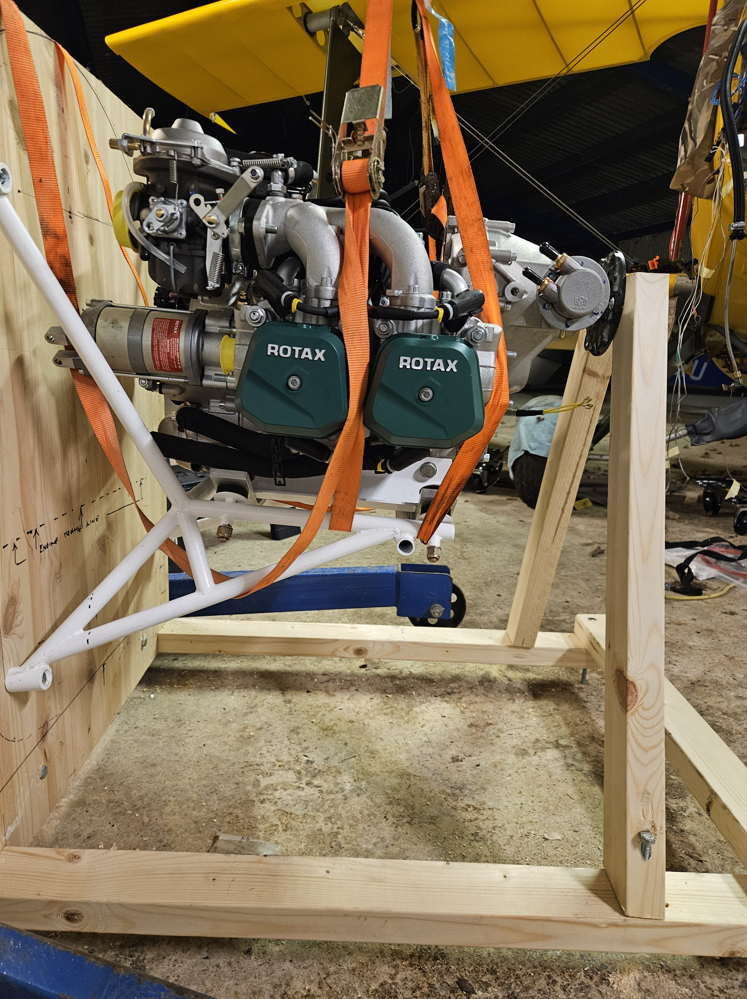
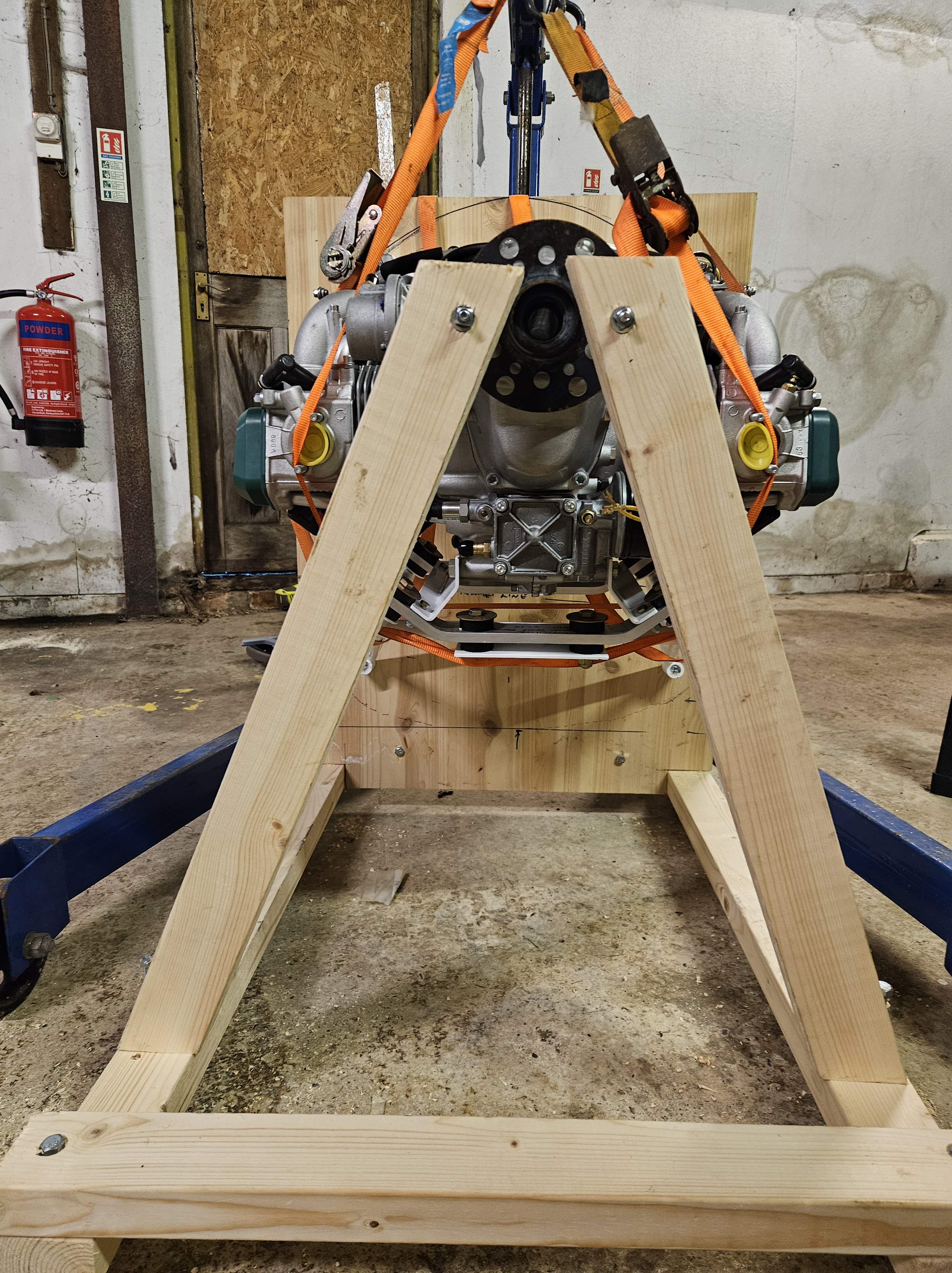
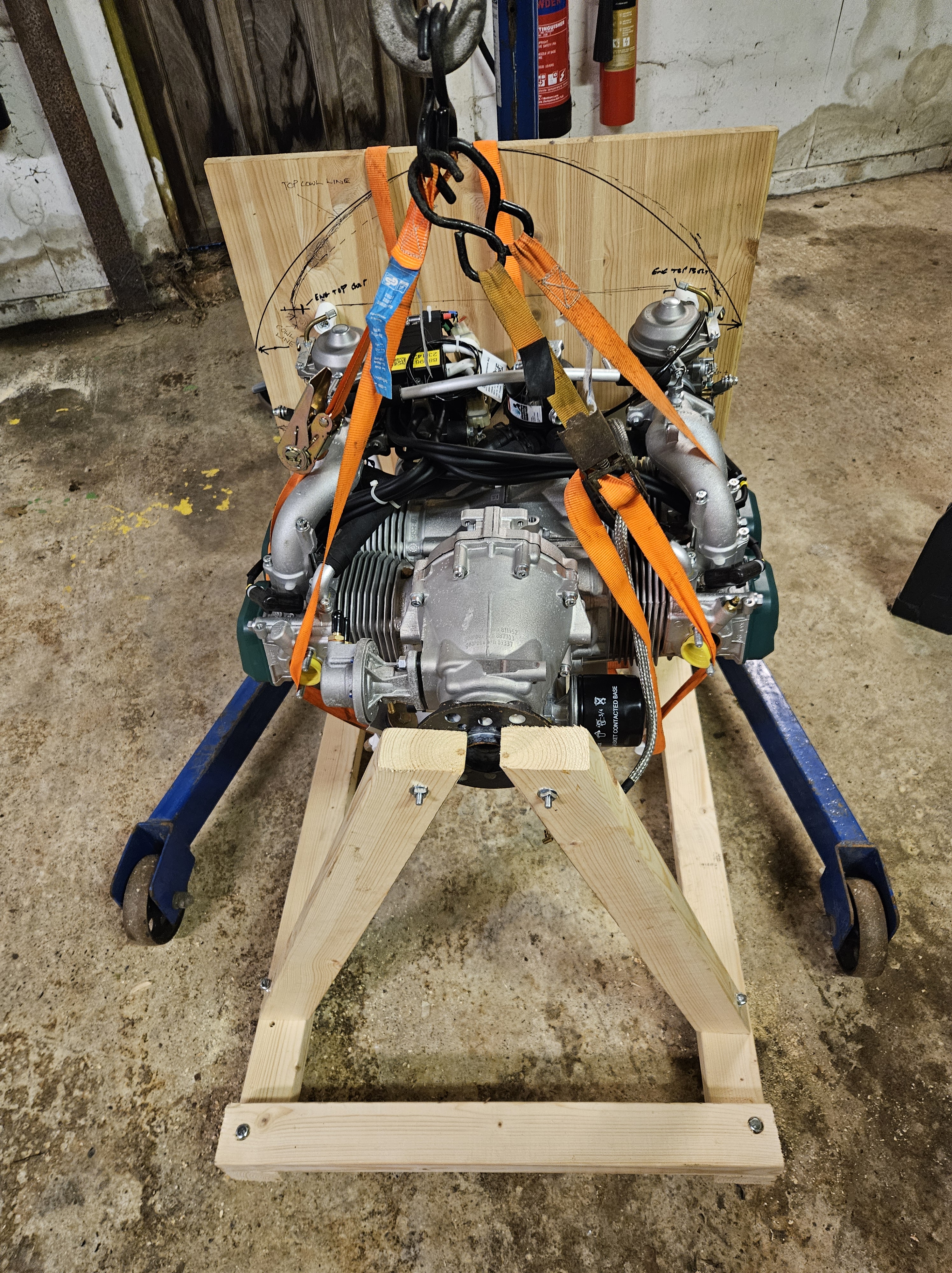
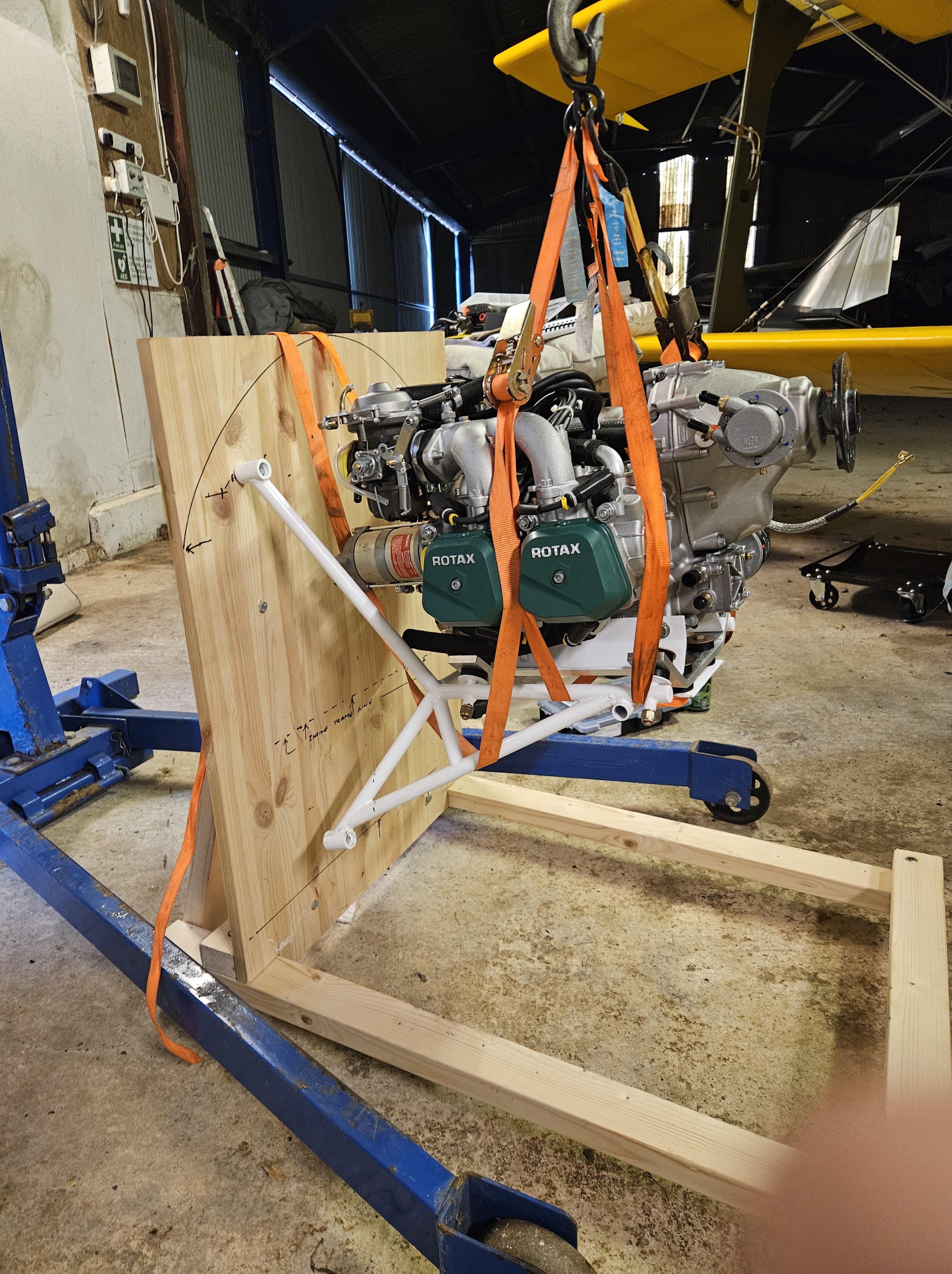
To make it easier for the engineering company to work on things (and they originally suggested perhaps taking the aircraft to them), I decided to make a cradle for the engine to mount in, and try to represent Firewall forward.
This should give them the body line as well as lots of room to work as they assemble the parts in situ and bracket up.
At some point, and now with ready access to the rear of the engine, I can look to heat up the water pump mounting bolts and feed pipes and realign 2 of the pipe exits so that the rubber coolant tubes miss the engine mount bolts.
Having bought the mice shiny new Rotax 912ULS i thought it would be a hop, skip and jump to getting her in and ground run…I was warned….
It turns out that sourcing something sime.like the water cooled radiator (something the Jabiru never had – being only Air and oil cooled) is a minefield !
Size, shape and properties are just the simple things ! Relatively .. the next main thing is actually sourcing one ..
You would think that would be easy but no … after much hunting around AND picking the brains of some French friends across the channel I have finally located a source … turns out their online system has to take your order and pre process it to calculate the (proposed) 25 Euro delivery fee… but … it doesn’t actually calculate it online. Their (intersting) way around this conundrum is to show a charge that is so off the scale .. it’s obvious that it hasn’t been calculated …
.. for the circa 300 Euro water radiator .. the delivery charge (pre estimate) ..is …not 100, not 1,000, not 10,000, not 100,000 … oh its quicker to say …
Euro 10,000,000 !!!!
Yes, I’m currently awaiting a (slight) decrease in my estimated invoice of 10,000,300 euros … I’ll let you know
The exhaust had been a similar and arduous dilemma until I located a Czech company who provided and shipped the kit relatively painlessly.
The oil radiator I’ve managed to source in the UK along with some throttle and choke cables and await these with my Horis instrument upgrade. The oil rad will not be mounted front and centre in the cowl as the fairly large radiator will make for some wide cowl cheeks .. so it’s going to be underslung at an angle .. say 30′ to the airflow but perhaps have a ram air duct to drive Air through .. the French have tried this and it seems successful on the relatively slow moving Ranger.
Once this ‘Eurovision’ of engine parts comes together it’s off to the local specialist for pipe shaping and bracket making …
Then we can start to think propellor and cowl… wonder which continent next 🤔
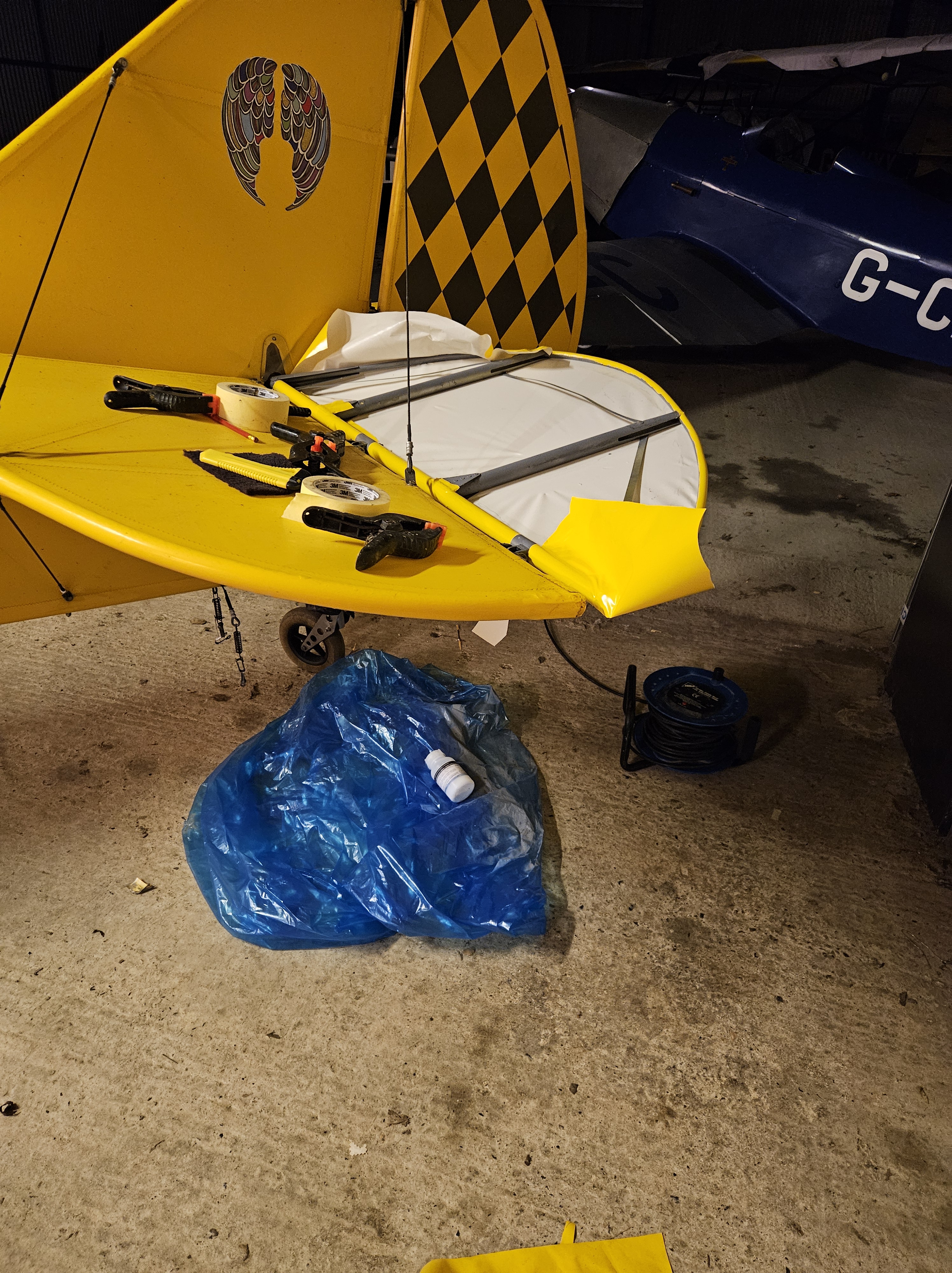
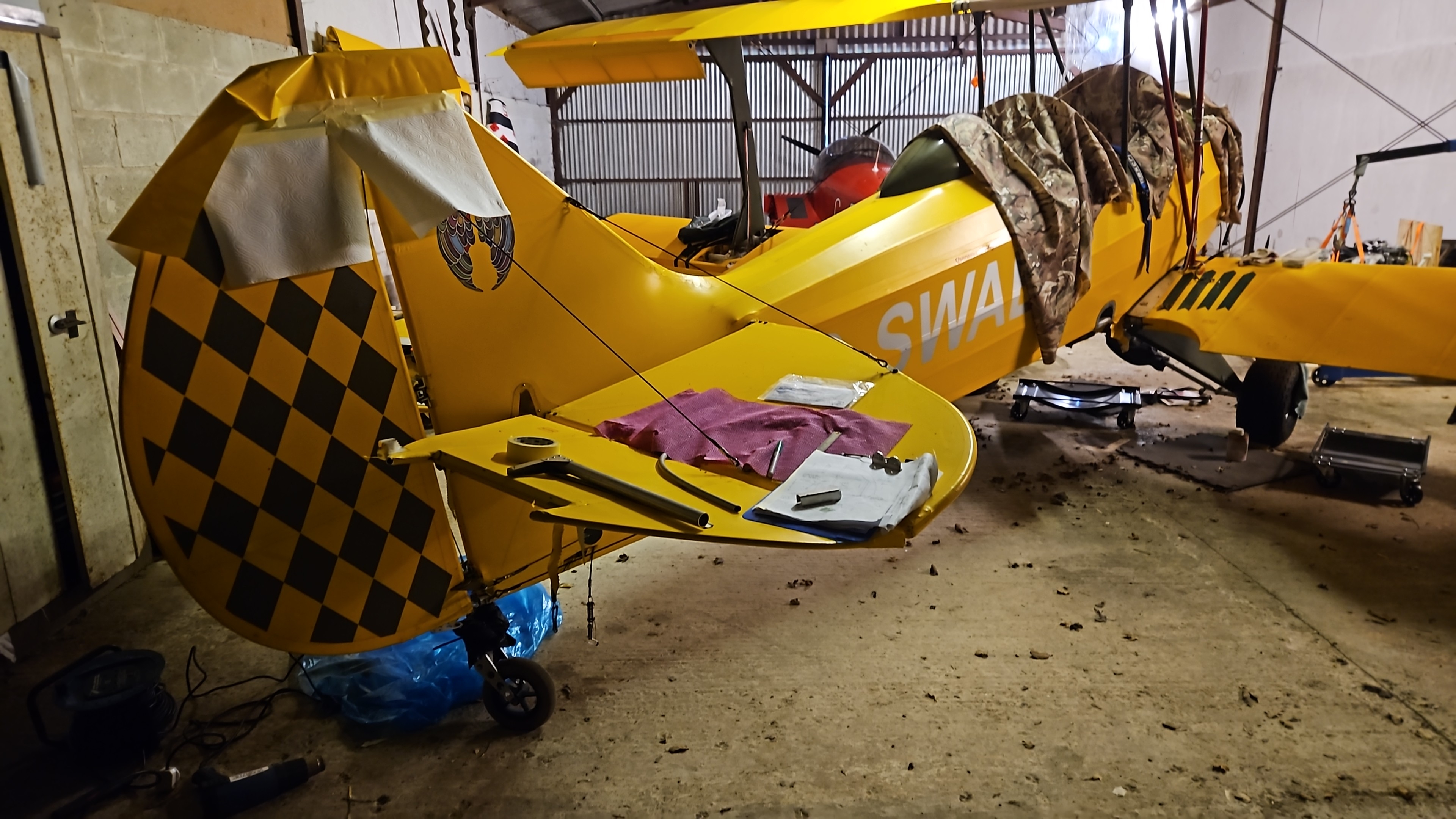
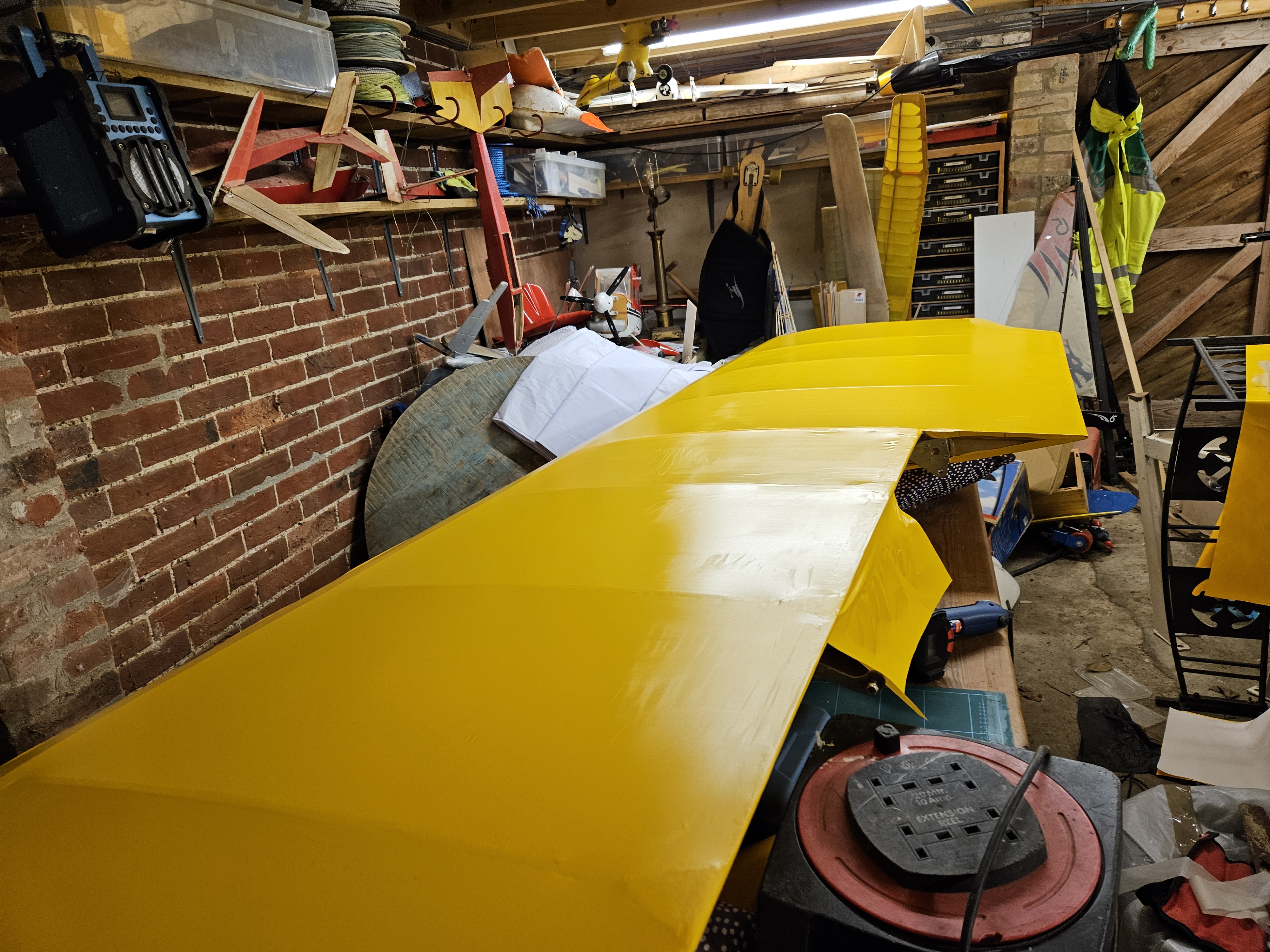
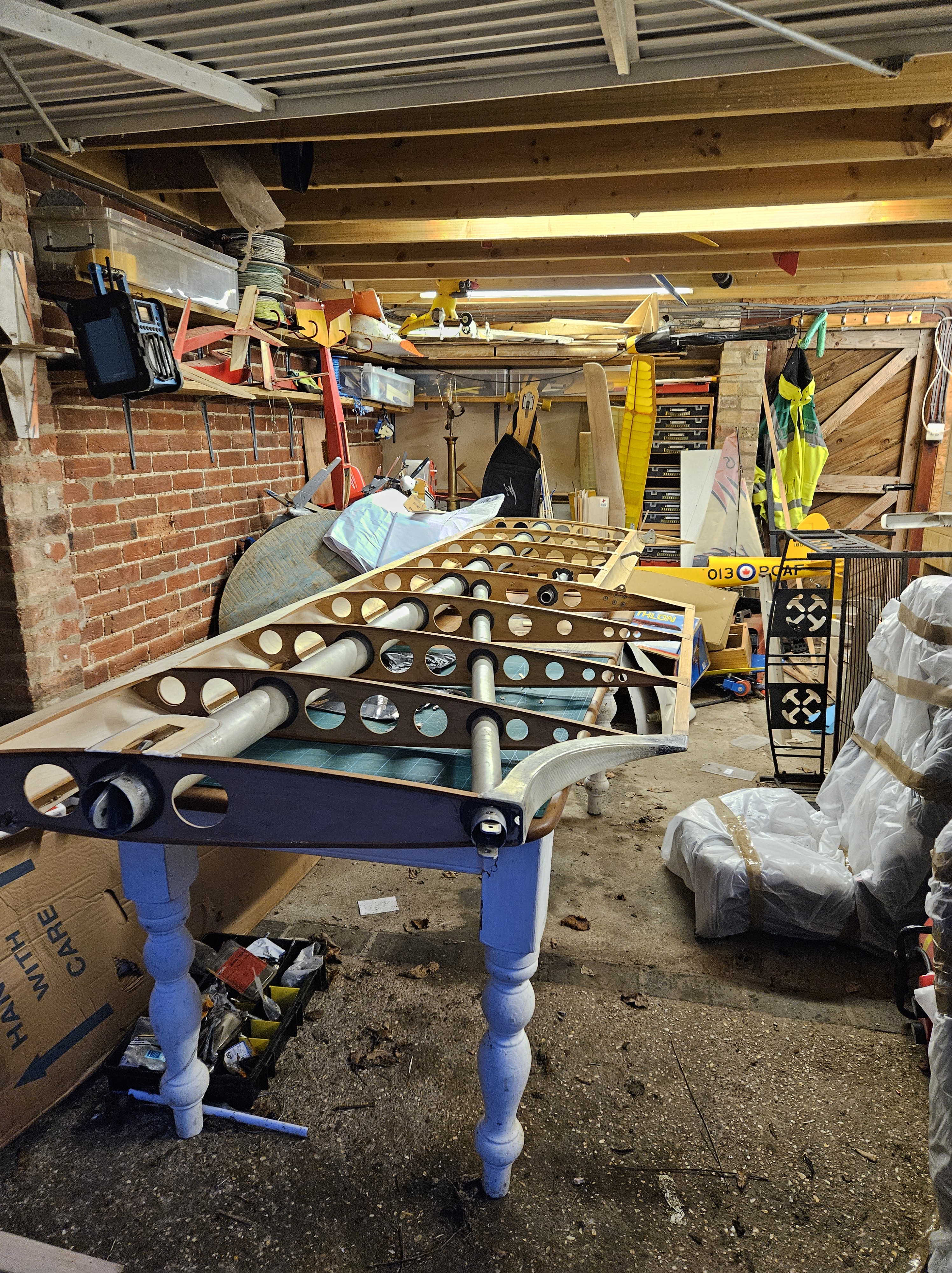
Having covered the first set of (4) wings nearly 7 years ago I’d forgotten how fiddly it can be 😊
Its a mix of frustration and sheer delight as the heat gun tightens everything to perfection
All the little bits in between are the challenging bits …
Making sure all ‘hard’ edges are chamfered down
Making sure you mark the templates for both Top and Bottom covering before sealing one side down
Checking that you have pre glued the wood surfaces as dried off surfaces don’t look like they have been prepped
Getting sufficient pegs or tape to hold wings down whilst you pre mark the glue areas
Getting the overlaps right.. in terms of size (top always goes OVER the bottom)
One key thing to remind myself .. once you have trimmed and pre glued and let it go off and get to the exciting stage of fit .. don’t charge ahead and try to tackle and shrink straight away
The shrink rate is about 25% and can easily pull the tag points away if they haven’t been allowed to cool
Having had the repaired wing back for a few weeks I have had time to replace aileron mounts, prep the bare wood (repaired) sections and add new rear strut support mounts, it was time to remove the wing (Port Upper) and drive it home.
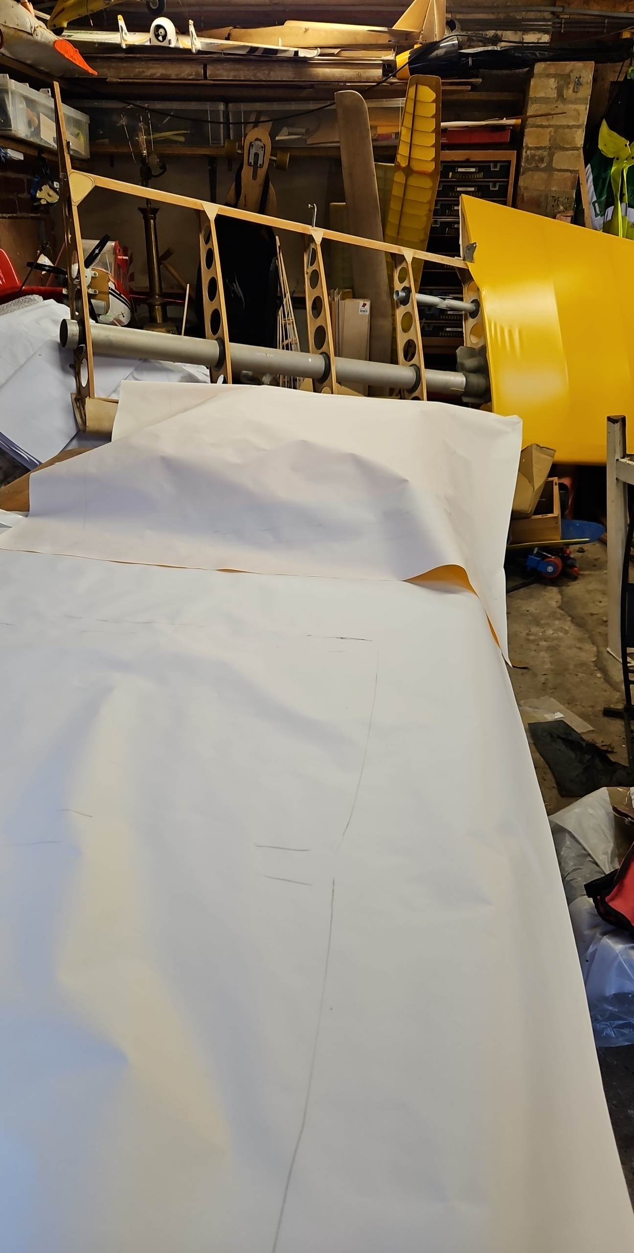
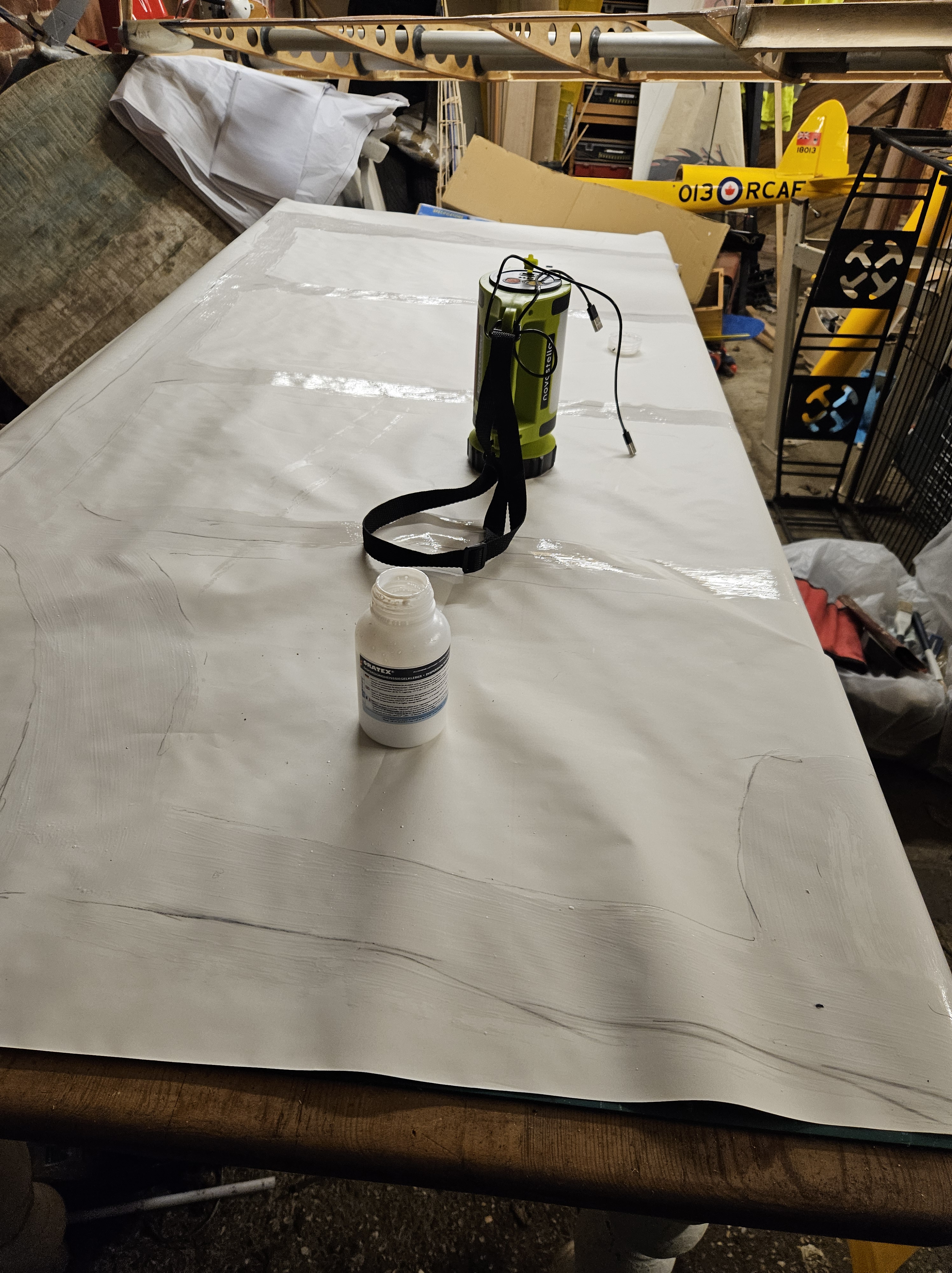
Safely in the garage, I could finish off the material landing plates where the glue had eased out and present some new Cub Yellow Oratex up to mark up the undersurface of the material where Oratex glue needed to go.
The first time i did this (some 7+ years ago) I overmarked the underside and the marks showed through in parts. This time I used feint marks with a chinagraph lead so as not to make too much of an impression.
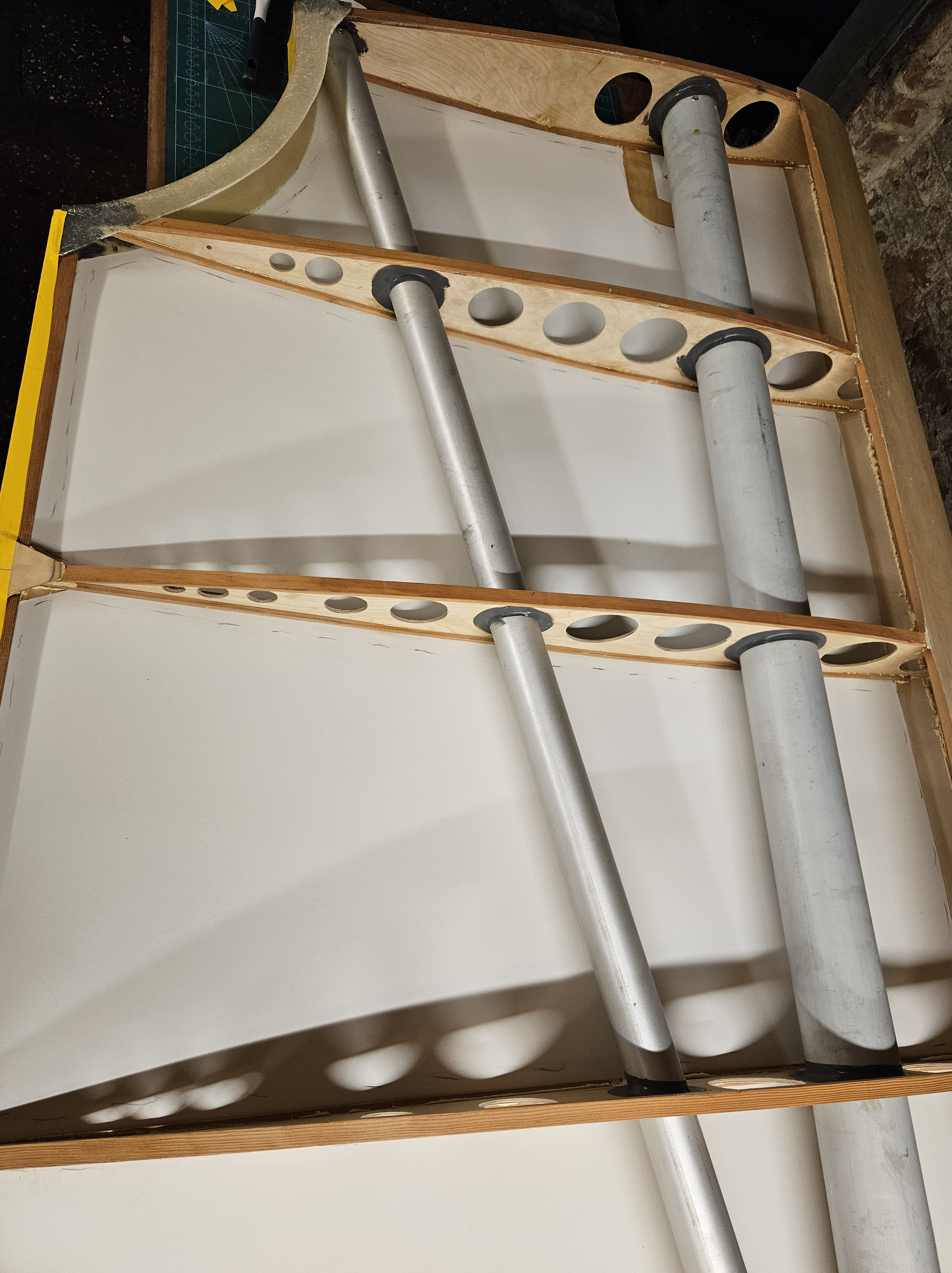
The underside of the upper wings have 2 large (removable) inspection panels so I’m changing from using a full length piece of material (root to tip) as its quite wasteful.
Instead, I’m terminating at the panel where the rigging cables and strut fixing plates are.
This saves quite a bit of material as well as making the size of the material you are working with more manageable and less like a slippery eel !
I usually leave the hotmelt glue to go off overnight although I know you can use a heat gun to accelerate the drying.
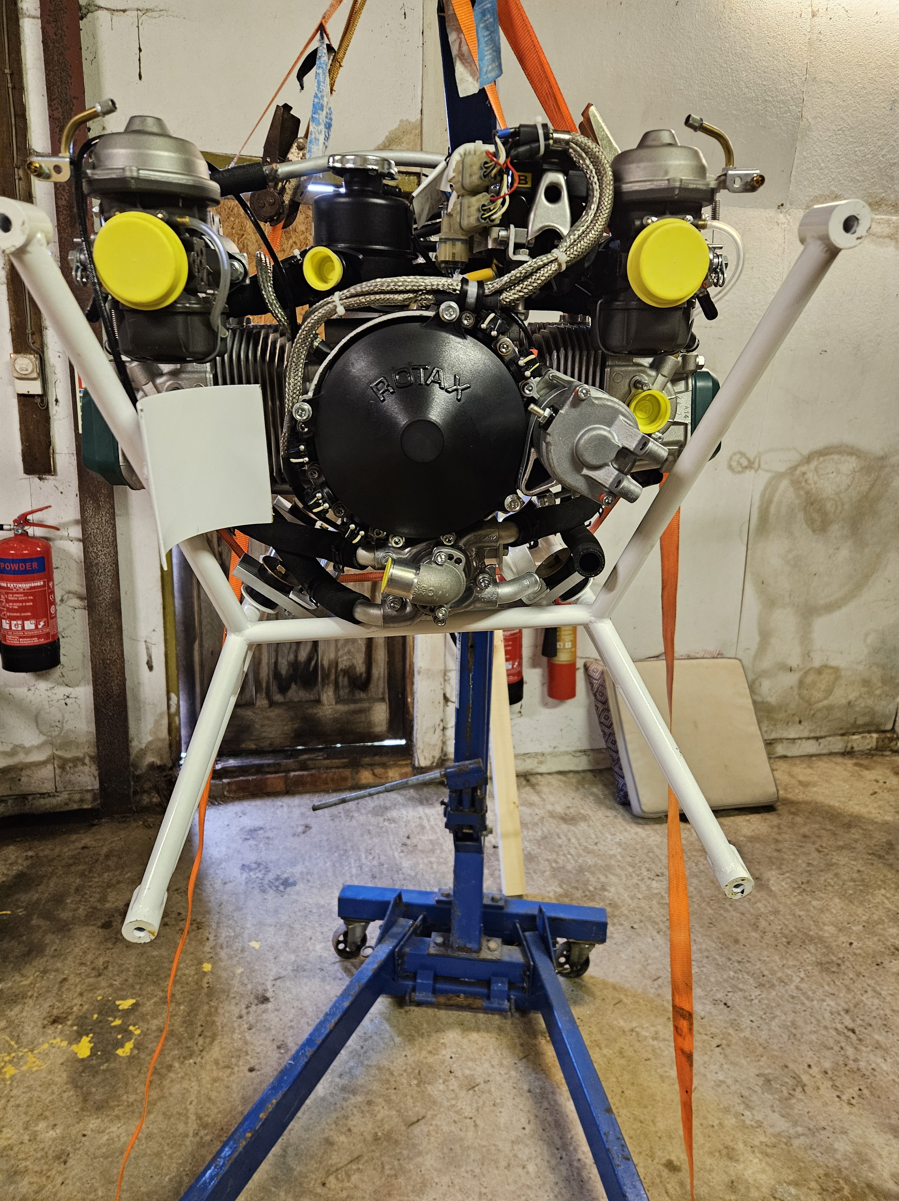
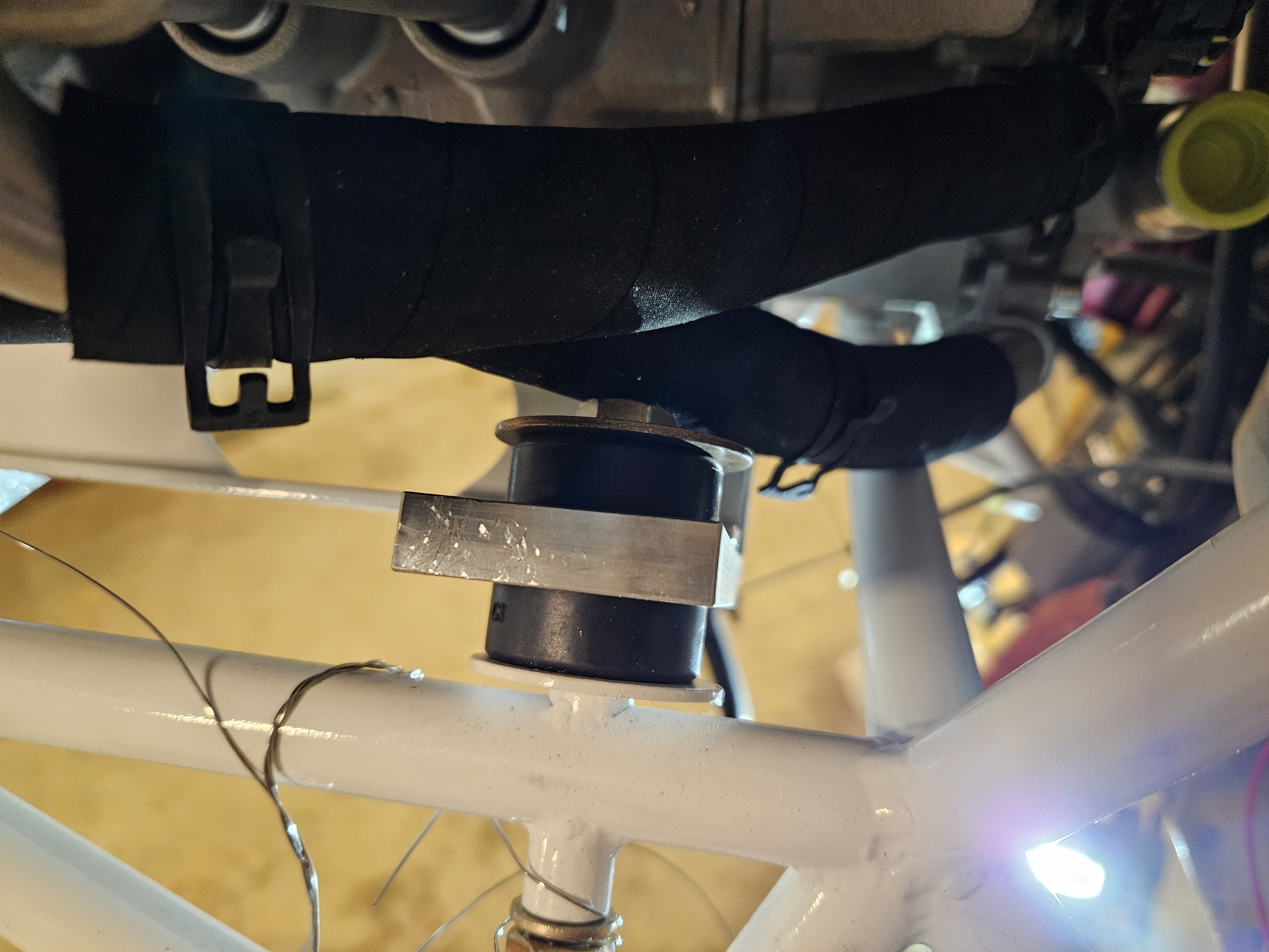
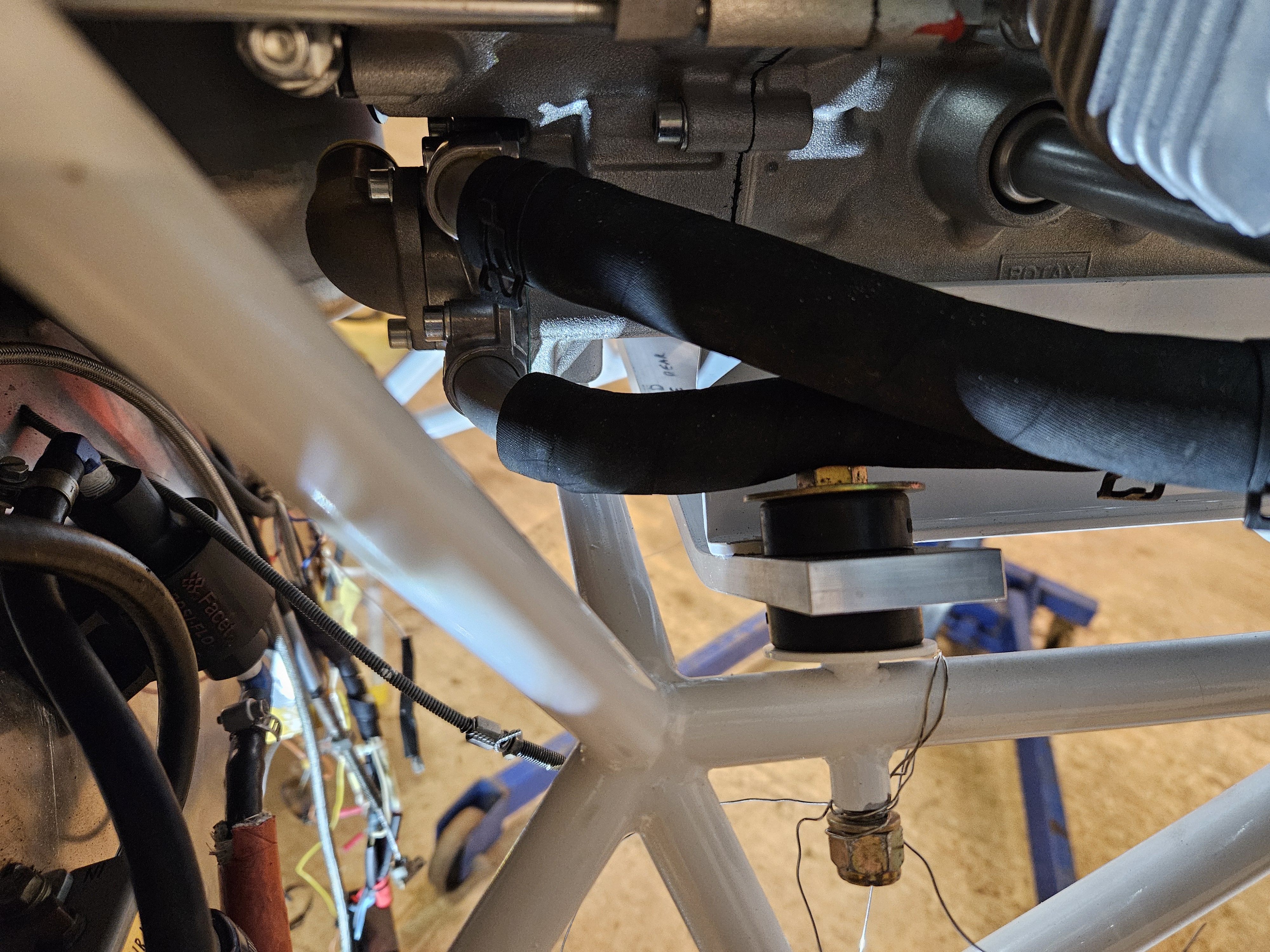
One of the things I’ve been concerned about is that the new Rotax 912 and new engine mount have meant that the coolant tubes run is too close to the engine mount bolts and the coolant exit pipes (that leave the water pump).need to angle slightly to ensure the coolant rubber tube misses these
A bit of research has identified how these pipes can be loosened and angled
Still struggling with the cooling system on a Kitfox IV w/ 912ULS.
In order to get the final hose installed from cylinder 4 to the water pump, I need to adjust 4’s cooling inlet fitting by about 10 degrees so it’s not pointing directly at the engine mount. There’s no way to install a hose without a kink in it otherwise. (Old hose had significant kink.)
Looking through the MM, I don’t see any text about removing or adjusting those fittings. There is a star next to them (page 336), but I find no correlating star in the text.
Going back a few pages to the water pump disassembly and reassembly, the same part numbers can be removed after heating to 180 degree F cleaned and re-assembled with a minimum of 5 turns and Loctite 243.
Is the procedure the same for the cylinder mounted elbows as the water pump? Am I missing something in the MM text?”