Engine – Pre Read

Off skiing at New Year so printed off the Jabiru 2200 engine manual which the factory have usefully put on the web. Time to get into what lies ahead !

engine Jab 2200

DSCN1592 DSCN1594

Got a brand new unused 3 year old Jabiru 2200. Converted before it left the UK to run on Avgas … nice to have a built in starter – compared to hand swinging the Gypsy Major on the Stampe ! Nice to have learned how to do it though and really makes you appreciate key/push button starters. I remember it was always a finger and arm counting job after starting ! and especially challenging on hot starts … anyone who can hand start a hot Gypsy Major 5 minutes after landing in Dinard and still keep a safe technique on the  20th swing !

Still need to source a prop – but have looked at the Hercules wood, and why would you pick anything else ! Just need to decide colour pin stripe to match ‘plane colour

Tailplane Ribs

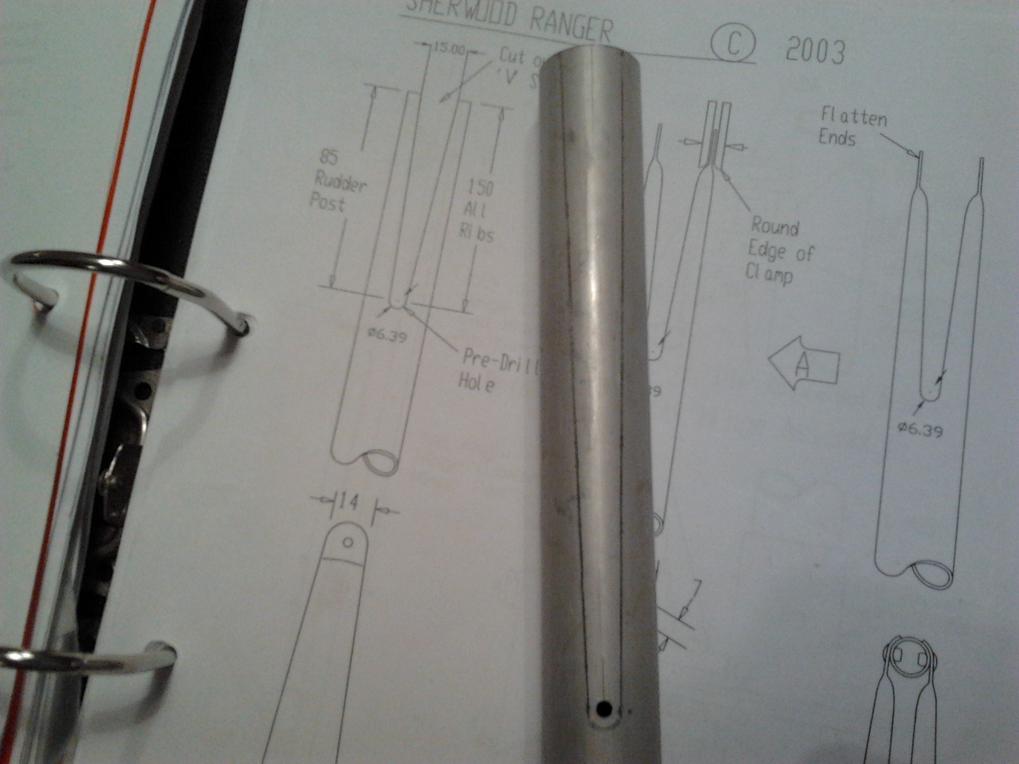
The 3 tailplane ribs are supplied slightly oversized and so require trimming back and shaping so that you get a neat joint with the rear of the Leading edge or the front of the Trailing edge. This is slightly trickier when the centre rib, which angles at around 45′ comes in to make a neat joint in the gusset sandwich.

Taking small amounts off with a file and constantly checking and re-checking helps.

Tailplane rib joint closeup

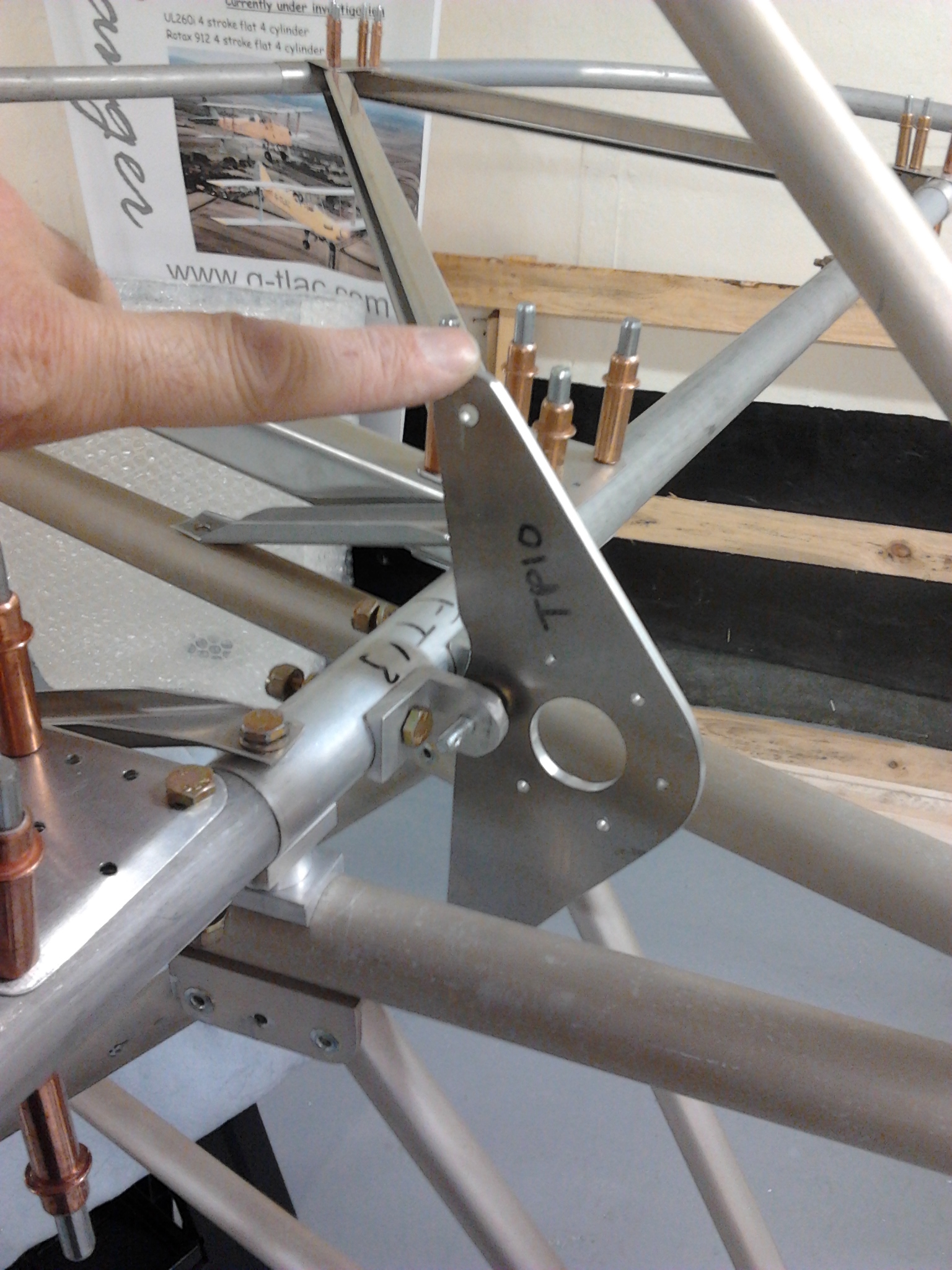
This part is quite satisfying as each part you add makes this look more and more like an aeroplane and again, withe the Sherwood, stronger as each componant is fixed into place.

Tailpalane ribs

All this is a temporary fix at the moment as the plan notes you have to remember to remove all this for covering. First I have to remove it for two reasons,

1) I managed to drill one of the underside gusset holes directly into a cleco and broke the drill bit (part of which is now inside the tailplane leading edge … a simple dismantle and hold it upright will remove the part !

2) I need to treat the internal tubing against rust – so will be thinning down my waxoyl to run this through.

Tailplane – First fit of leading and Trailing edge

Leading edge requires trimming once it is pushed fully onto the mounting shafts. Each plate / gusset requires cleaning down so that you dont leave any sharp edges.

Then start to fix in place with a few holes cleco’d to get a basic layout

Note the sandwich gussets require shaping so they follow the line of the Leading or Training edge

Tailpalne rib sides

Tailplane – First steps – Rear plane mount

The fast build kit comes with the leading edge mount for the Tailplane in place. The rear mounting consists of a sandwich of saddles and a nice neat turned alloy tube and a couple of leading straps to be cut and shaped and then the seatbelt harness securing point is put in between.

Having drilled the saddles the metal lead straps are bent to form a neat align with both the frame and the top bolt.

Tail Trailing edge mountTE Mount with harness bracket

Tailwheel rebounds

After a number of attempts to get these on and proving that this is not the task it first appears …

Checked with Bob at the Aero Club and he wasnt happy with my second attempt at the whip binding. Not tight enough and not neat enough ! Re tied as tightly as humanly possible this evening and it looks much neater.

Sequencing what is part assembled, what bolts are put in place, what parts of the steerable bracket are in place and then finding something to get those very tight straps around the wheel post. Having got the first one on using an old (well it is old now !) coat hanger …. The second one was having none of it …

Eventually remembered my old ball joint splitter from my MGB Roadster days … slid steel but with a forked point. BINGO ! got them on….

tailwheel rebound

Rudder – top rib – first fit

The top rib consists of two halves that need to be shaped around the ruudder post and then trimmed at the leading and trailing edge to fit around the shape of the rudder trailing edge. The rudder trailing edge is provided pre shaped but oversized so you need to trim once you have applied your first temporary cleco fit.

Paul advised to start at top rib first and work down. Cutting through the top rib halves made me feel it would weaken this piece too much as it has to fit snugly to the rudder post. Far from it .. once cleco’d it is incredibly stiff and looks like it could take great force !

Once sure it is still looking square with body, you can start to temporarily fit the other two ribs in place

Starting to look like a real aeroplane !

As each rib is shaped and secured (with clecos initially) the rudder trailing edge will finally be trimmed at the bottom of the rudder post where it sits in a 13mm hole right through rudder post.

Rudder post, hinges, first fit of trailing edge

Post needs to be shaped and hinges drilled out and set.


Wasnt sure I could accurately cut the elongated ‘V’ into the top of the post and the trailing edge of each rudder rib so got a local company to assist. They marked and cut with a grinderandmade a great job. 

Hinges are pcked with temporay washers to get the hinge sitting in the middle of the bracket.

Rudder horn is cut from plate, drilled to take alloy turned collar and then pushed onto bottom of rudder post. This proved quite tight and so had to be chamfered down to take. Rembering to leave rudder leading edge hole rivet free to act a hinge point.


Before mounting, drll 13mm hole through bottom of rudder post to take trailing edge, then temporary first fit to see it it looks right !

Paul advised that the trailing edge is overized to allow builde to cut down so that the ribs fit tightly 

Rudder parts next

Identify all the rudder parts .. these include the nicely pre shaped trailing edge from the factory.

The rudder post and two main ribs need to have ‘V’ slots cut in to allow them to be shaped around the trailing edge.

The top ribs need to be marked up as per diagram and trimmed, finally found some good cutters that do the job.

Assembly is in situ making sure everything is lined up.

Wheels together and inflated

Drilled out the inner half of the hub to accept the 6 fixing bolts.

DSCN1650

Then seated the larger half into the tyre centre, carefully pulling the valve through the valve hole (drilled earlier). Make sure it seats comfortably and is not straining the valve or jamming the inner tube at all.

Use fairy liquid around the tyre inner rim to help it pop onto the rim as you fill with air. Boy does it go with a bang ! ..make sure your fingers arent nea the lip when its filling !

Finished wheel on rim


Bolt the other half of the hub in place tightening opposit diagonals to make sure it tightens evenly. Then soap the tyre inner edges on both sides to encourage it to pop out onto the rims when you inflate. It takes a while for it to pop out so make sure you keep your fingers clear. With two loud bangs it pops onto the rim !

Now deflate completely … I bounced it a little to make sure it sat evenly, then reinflate to standard pressure (2 Bar). Check bolts again.

Soft fit and check brakes dont bind

Just need the yellow paint to mark the witness marks.

Blog at WordPress.com.

Up ↑