First aileron fitted – Port Lower

At last …. finally got first aileron fitted today … plucked up the courage to align and mark up hinge fittings then drill through, countersink and duralac through wood. Washers were shaped to fit in parts to provide beefed up face for wood face.

ail hing 2   ail hing 1

Then put in place and temp fit end bolts … should give even top gap of 4mm min ….to allow for tilt

ail 3 

The concave wing ply web comes up nicely when the 1.5″ plastic drain pipe and clamps have been removed then the excess trimmed off … feels like a real aeroplane now !

aileron web

Wing foot rests

The plan offers details of a single foot rest but mentions you can put one on each side.

To save the awkwardness of ALWAYS having to tell people they must only get out of one side, I have decided to add a step each side. The plan states 3mm but checking with Paul its 6mm ply which my Dad kindly sourced for me at a model shop in the UK.

The only ply available in Jersey is a veneer top and bottom and rubbish in between !

step port

The steps have 2 x 1 hardwood batton doublers spanning main and drag spars and these are then planed down to follow the contour of the ribs. The ply foot plate is then shaped and the whole lot epoxied to spars and battons.

Once in position the leading (and trailing ?) edge of the footrest is blended in by slighlty building up the ribs and then sanding down. I guess you then dont get a step change when the material (Oratex) is applied.

Aileron Web

Now the fun starts of fitting the ailerons….

The receiving part of the trailing edge has a curved web of ply to be applied. Firstly this needs to be scarfed over about 10 mm to provide a single full width piece of ply. The ply then needs to be wet and jigged to provide a slight curve. This will make fitting it to the ‘plane easier as the ply has significant spring in it.

The cool and slightly damp barn is worrying as I want the glue to go off properly. My friend Colin lent me a petrol powered jet style heater that I used to warm the whole body up in the summer prior to painting. Havent used it since but plugging it in and flicking the switch get a jet flame out instantly and the barn begins to warm up in seconds.

Even so – it proves difficult to ‘train’ it to the curved trailing edge. After many dry tests I’m still not happy its seating properly with the clamps. I then try some small plastic drainpipe pieces that provide constant span pressure against the curved concave surface. This seems to do the job and a number of judiciously placed clamps finish the squeezing exercise. I will now leave the aerolite to go off properly.

ail web support

Smoke system – LAA MOD’s

Some time ago I decided I would like to add a smoke system – on the basis that if you dont add it now (whilst you have a fully open structure) you never will !

I would not intend to use it every flight but it would be nice to have the option to ‘Smoke on’ if the sky was blue and the sun was out (if it ever will be such again !!)

The original supplier I found in the US decided to cease production so my initial MOD2 request LAA stopped after Francis Donaldson at LAA kindly replied and indicated they would be happy to see the MOD3 as long as I added a manual cut off over and above the electrical cut off.

Smokin Tank

I then located Smokin  Airplanes who offer a very neat unit and will ship all the mechanics (minus tank) and their very helpful site shows worked examples of both fitting and FAA submission details.

I am now working closely with Paul at TLAC who is kindly advising on location/weight/balance

Propeller – Hercules

Propeller arrived and was shipped to Jersey in a large heavy duty tube to protect it …

What a finish – most people in the office (whether interested in ‘planes or not !) seem to have come in and stroked it ! Fantastic layered beech and great finish.

prop 1 prop 2 prop 3

Rupert from hercules has kindly taken some picture of it during manufacture for the blog so that will be good to see the history.

prop press   prop cut

Realise I now need the prop bolts so Paul at TLAC is kindly helping with those

Wing and Cabane Leading edge

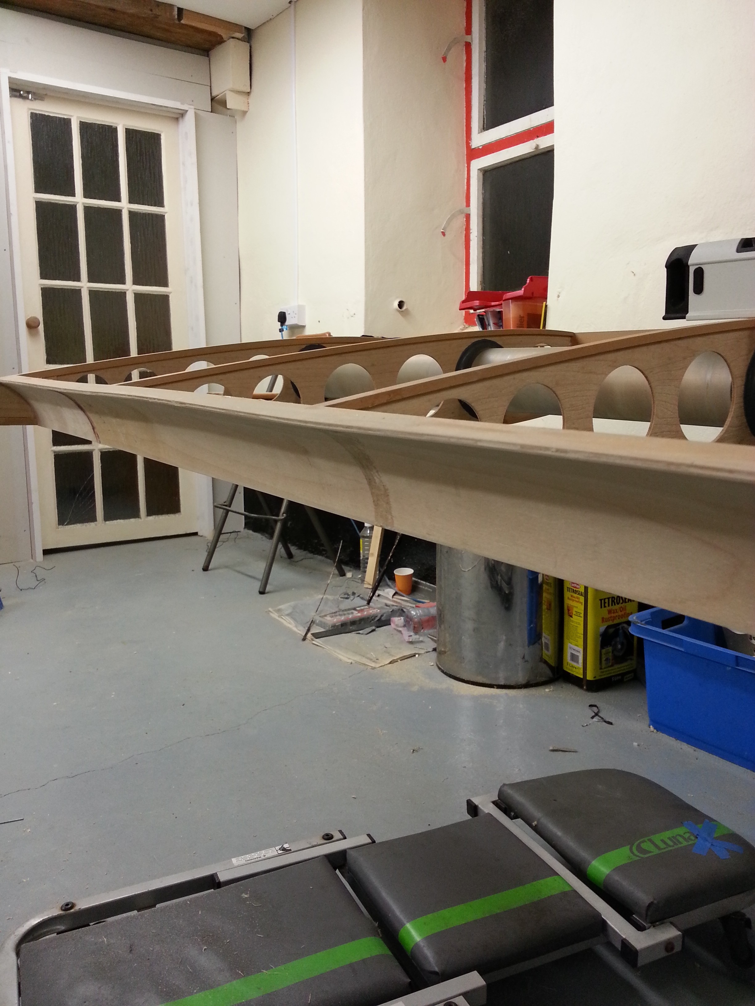
Leading edge is formed from slightly stiffer 1.2mm plywood. Years ago, when I used to build the odd model ‘plane here and there we used to pre soak ply to ease the bending so asked Kevin Crumplin on this when I saw him in Henstridge just before Christmas. Absolutely was the reply ! – a pond or bath would do !

LE Bath

Soaked the first of 13 pieces in the bath last night – this section will form the cabane leading edge. Once cabane is done I can get it fitted back onto the body and plan to test fit the top wings.

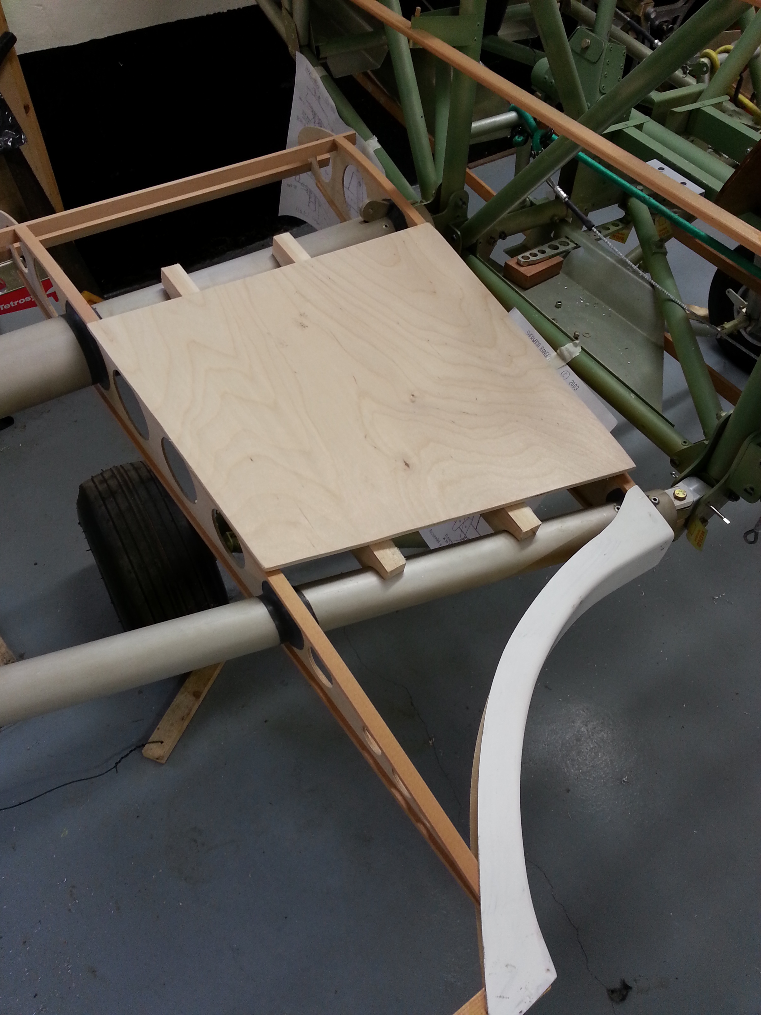
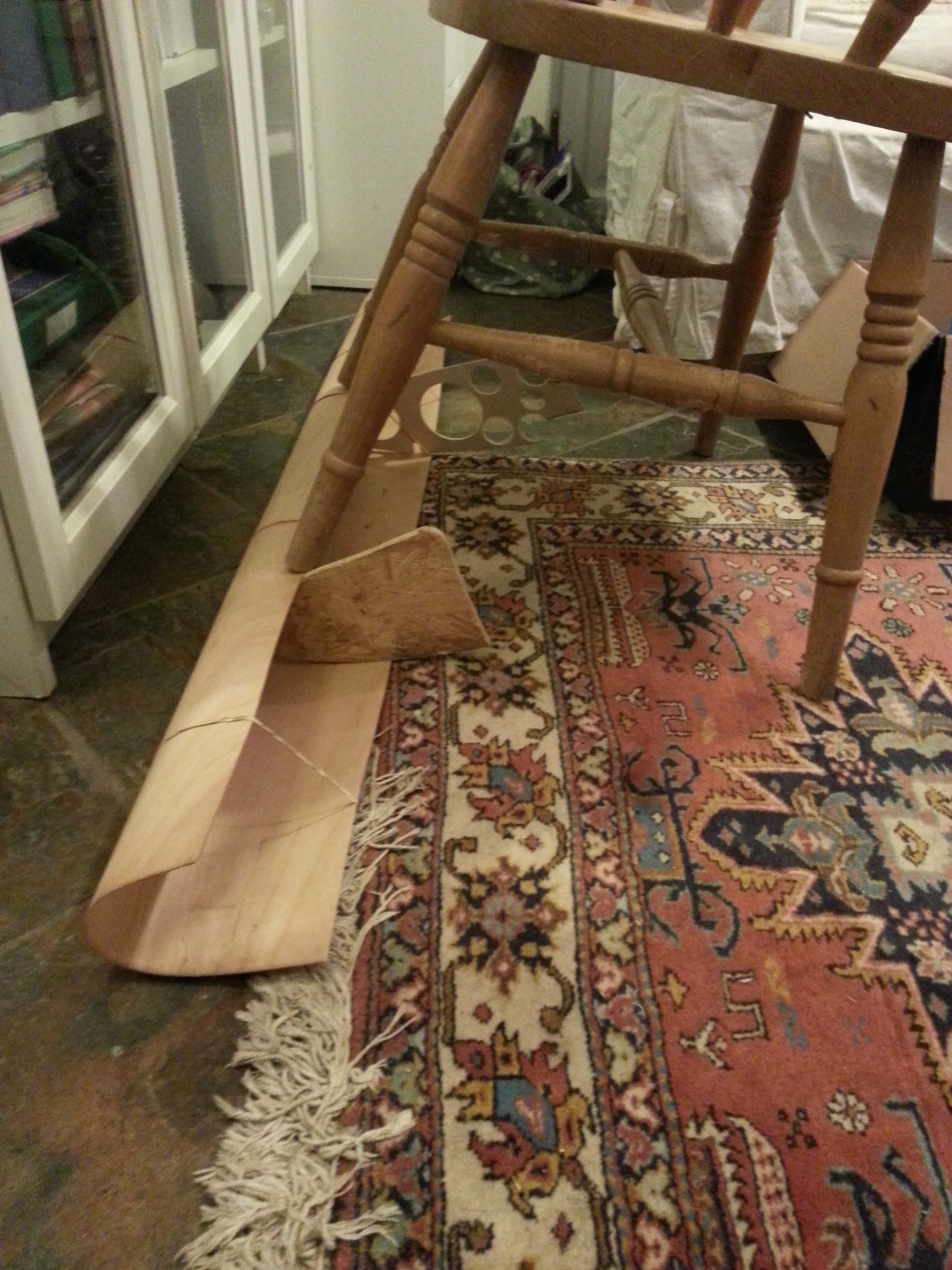
I made up a small jig to hold the now very wet and partly formed leading edge in position for 48 hours to let it throughly dry … the small strip inside the foot of the jig is to push what effectively will be the leading edge in to form a tighter curve … this took a few goes to get the jig right to effectively ‘over bend’ the curve … this means when it’s dried you get a springy BUT grippy leading edge .. which makes subsequent clamping whilst glueing a very easy affair
D0F85837-3A91-4D1F-BFA4-4D49B5FDB3A7

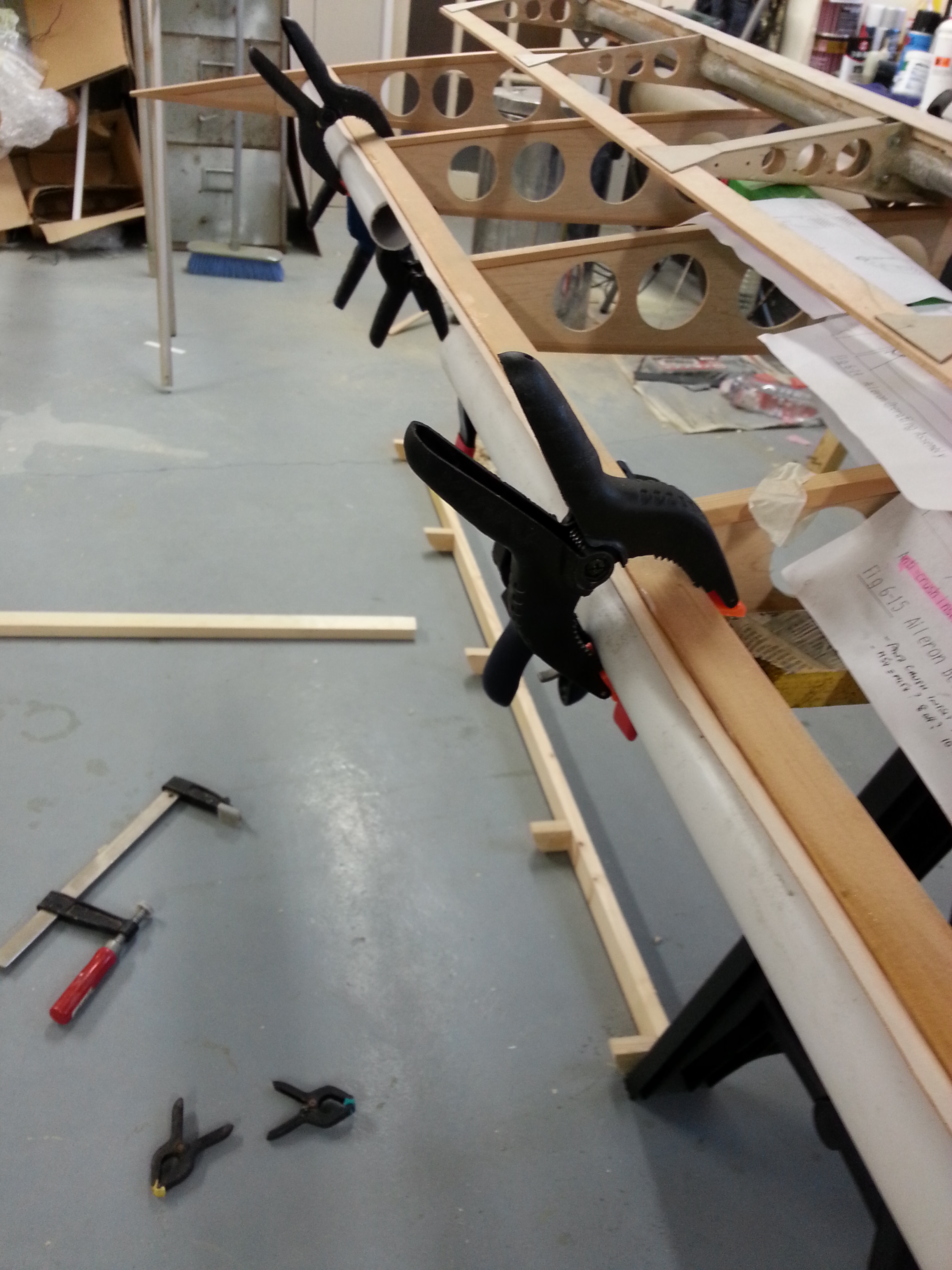
As you can see – with a bit of ingenuity – rubber bands and a chair of just the right weith to hold but not squash … This morning its dry and pretty much fully formed so should be much simpler to hold around the profiled leading edge whilst the Aerolite glue takes.

LE Bending

Blog at WordPress.com.

Up ↑