Rigging and wing fitting

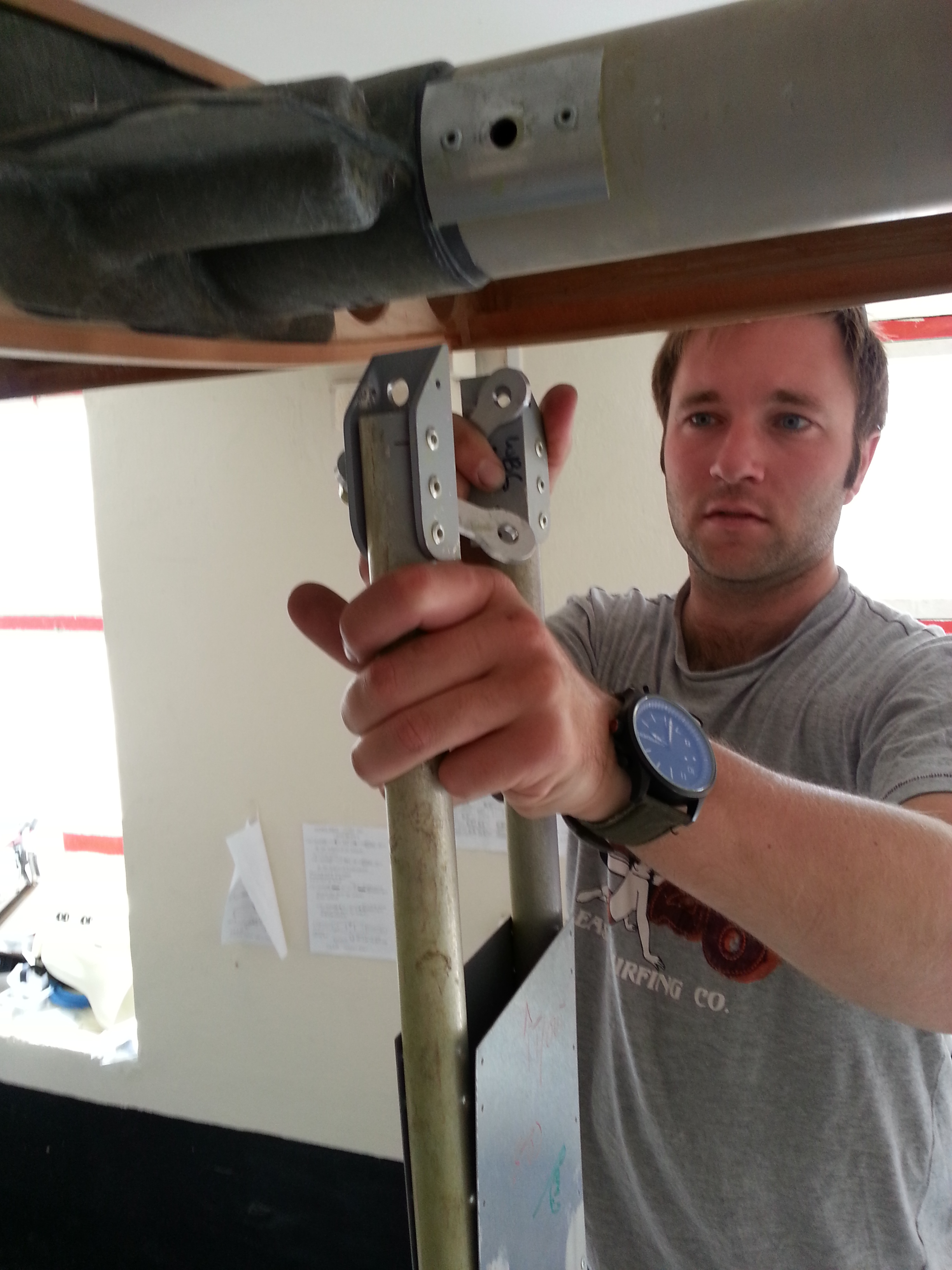
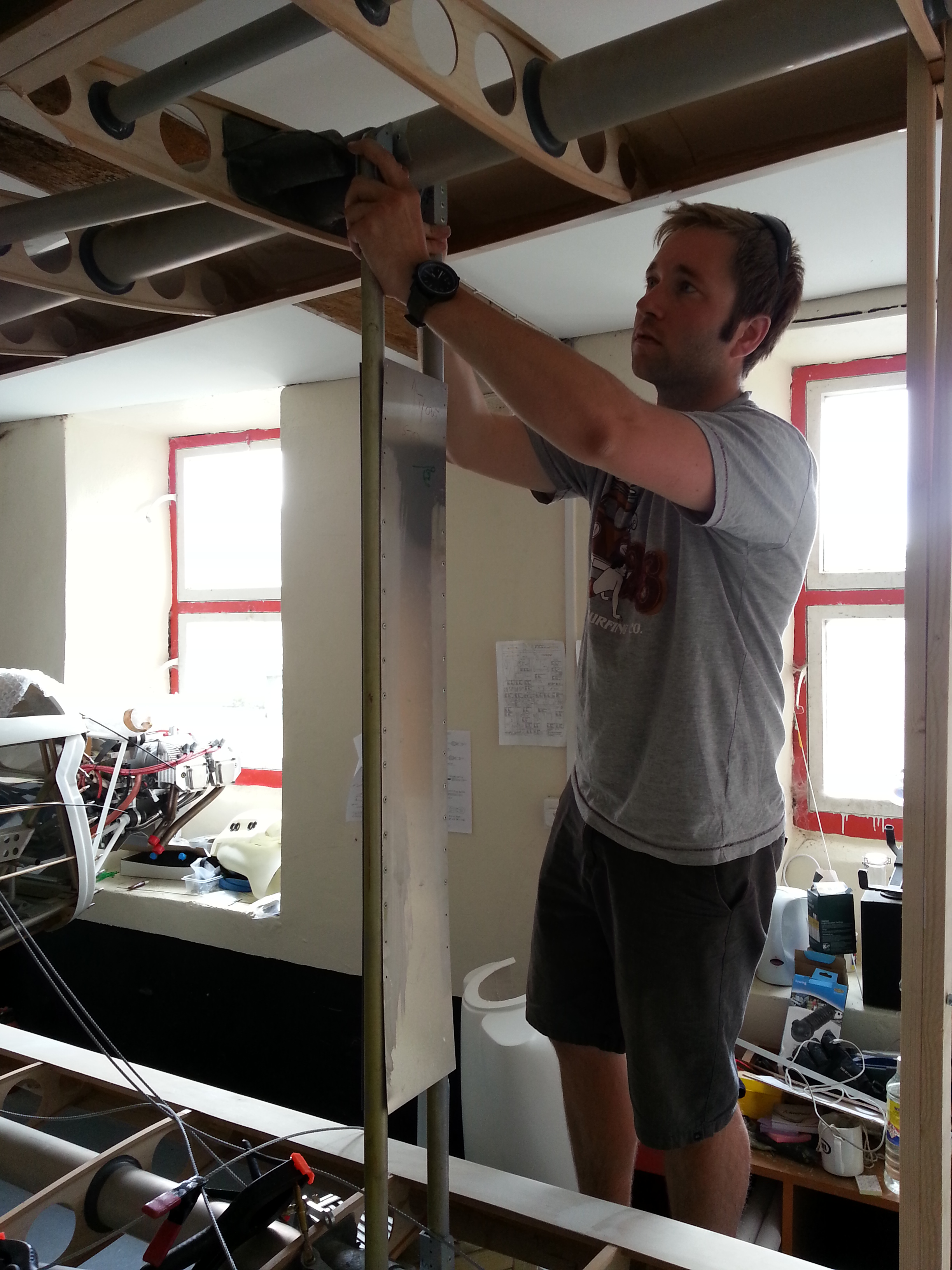
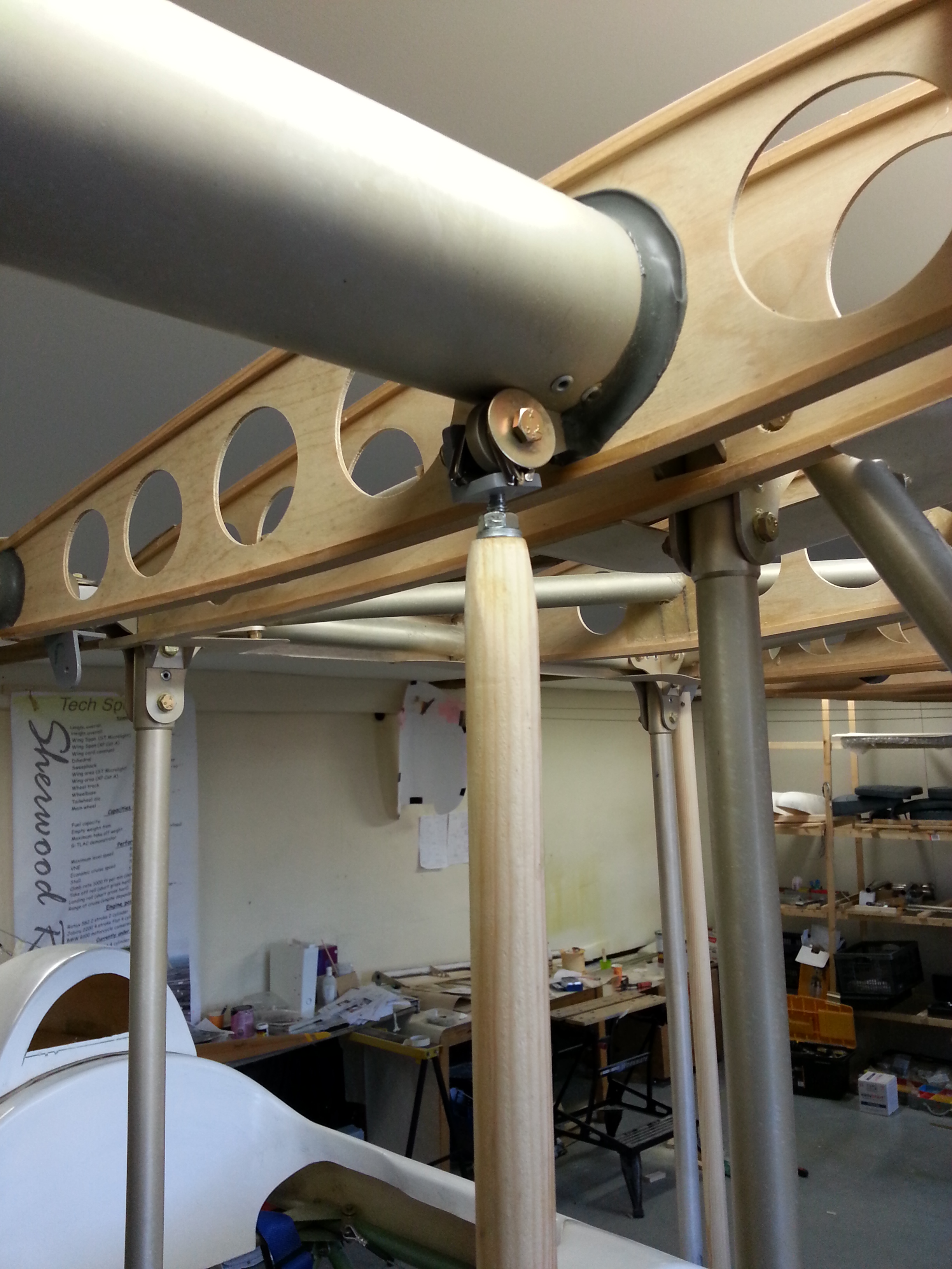
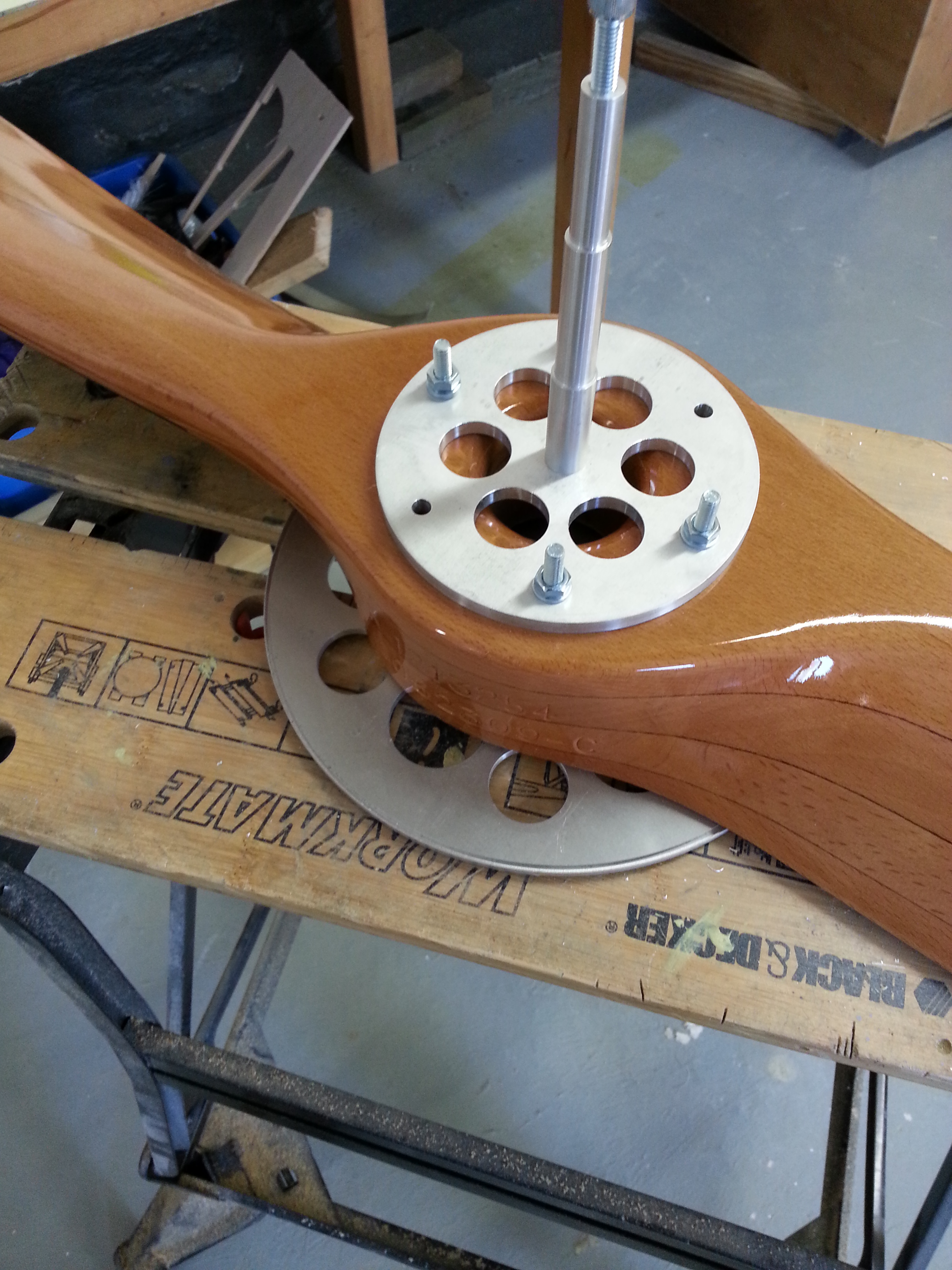
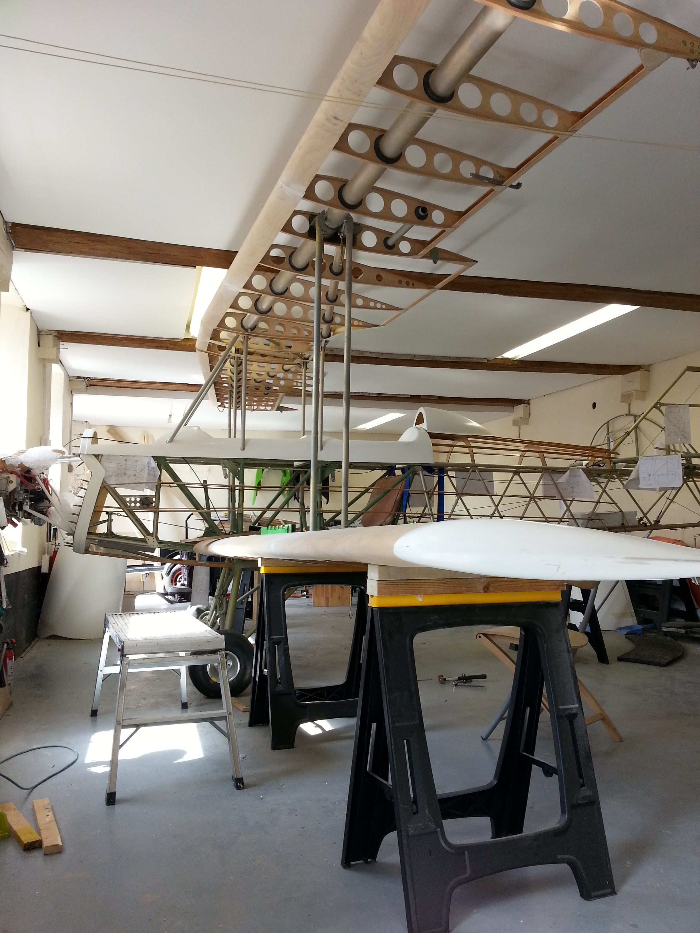
Hit a slight snag in that I cant get the drilling boss tool onto the rear top cabane (as the built up training edge prevents getting it seated in far enough to align the pilot holes). Mike Flemming is making up a shorter thinner boss that we can use so hope to get on and finish wing mount drilling shortly.

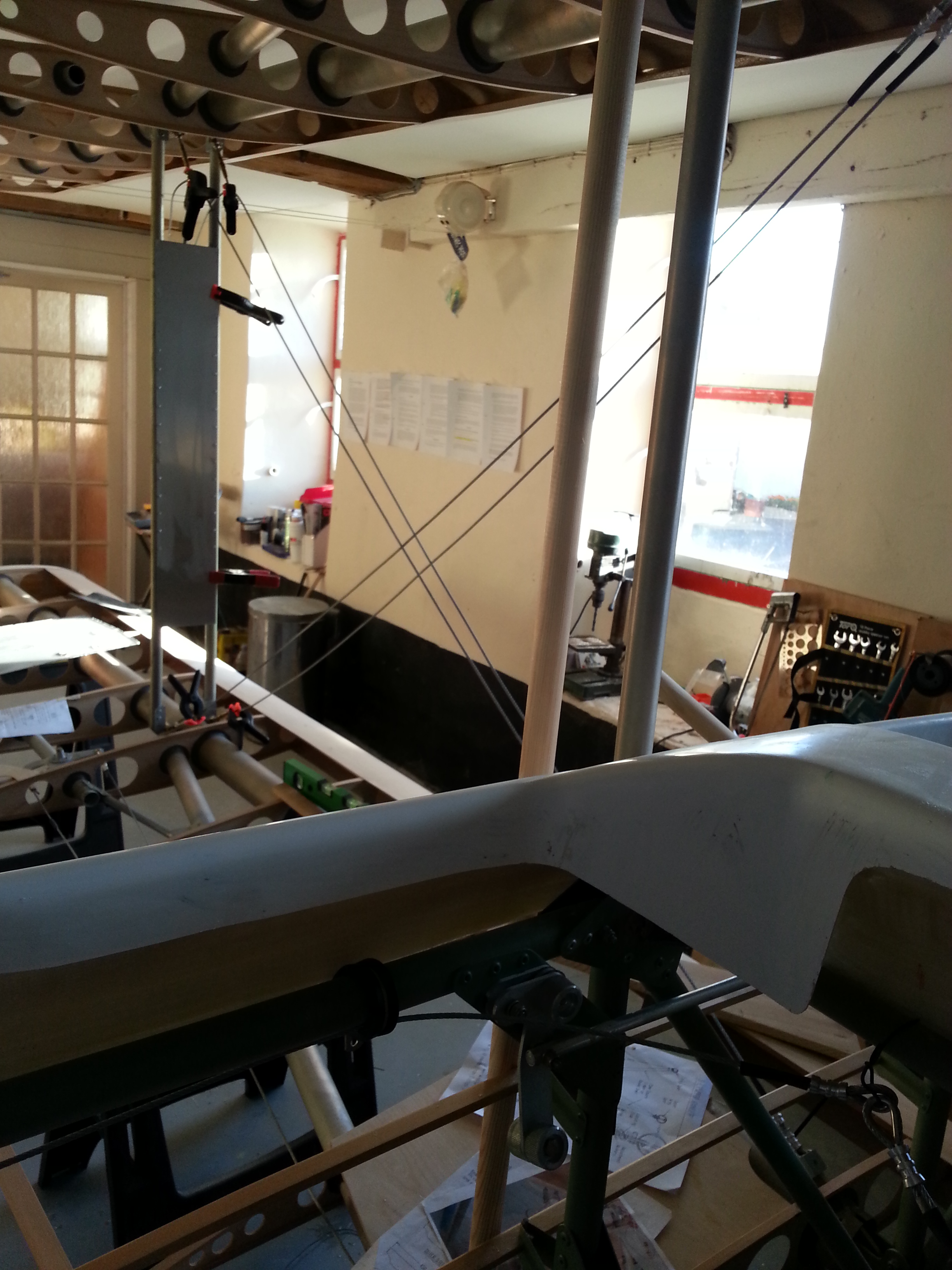
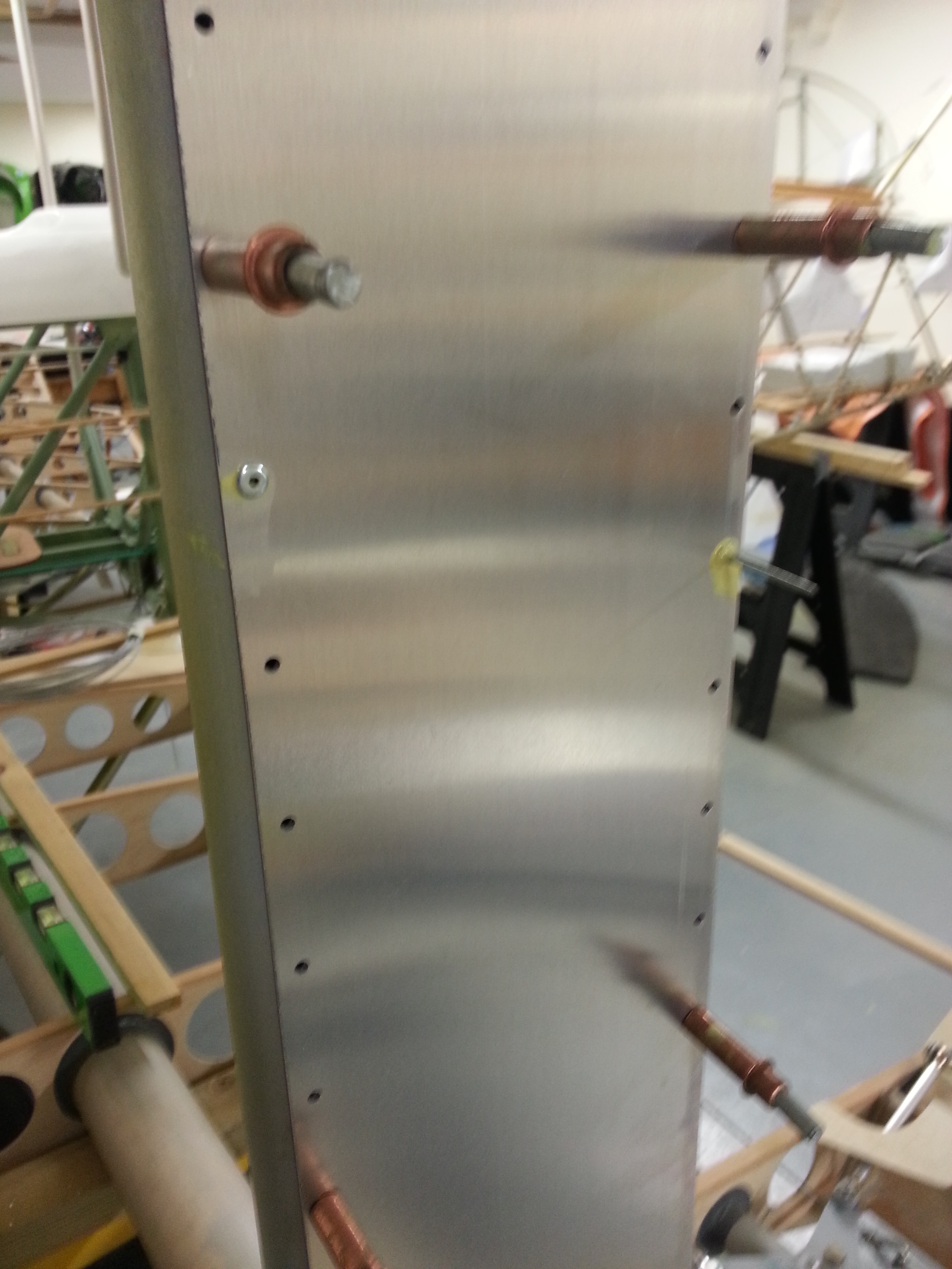
In the meantime the port wing strut can be re-fitted and, instead of temporary tying the flying and landing wires with cable ties I thought I would have a crack at the first crimped flying wire. I wasn’t sure how to set the turnbuckle prior to this.. should it be fully back off, mid way or fully the other way !

In the end I backed it off fully leaving a couple of threads in place .. this meant you could ‘see’ around 12 mm of thread at each joint. In that way, as you tighten the centre shaft they both close up.

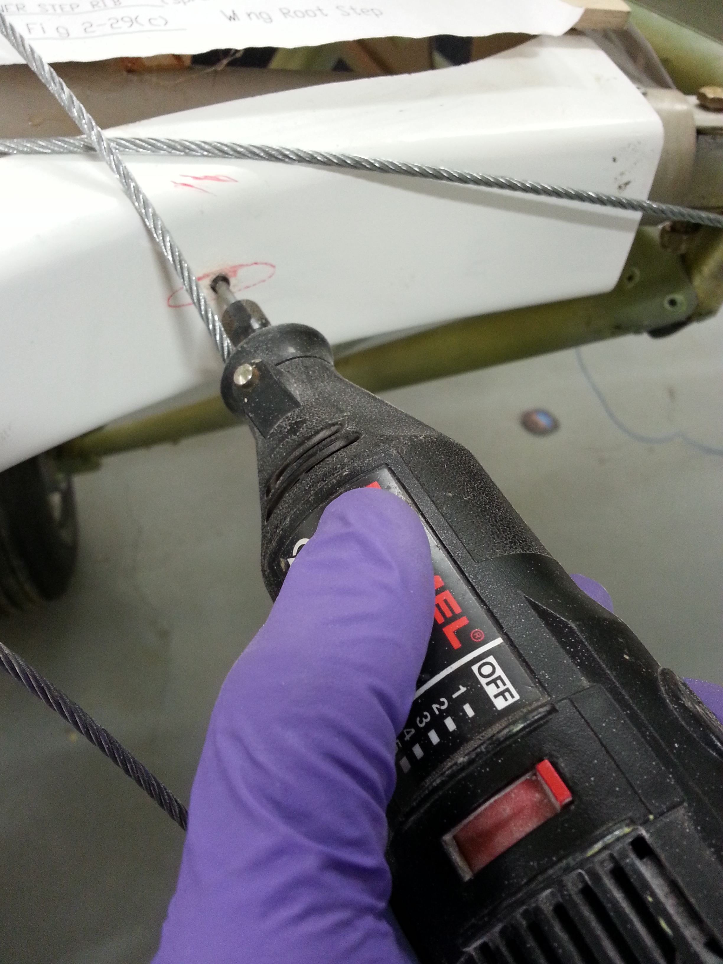
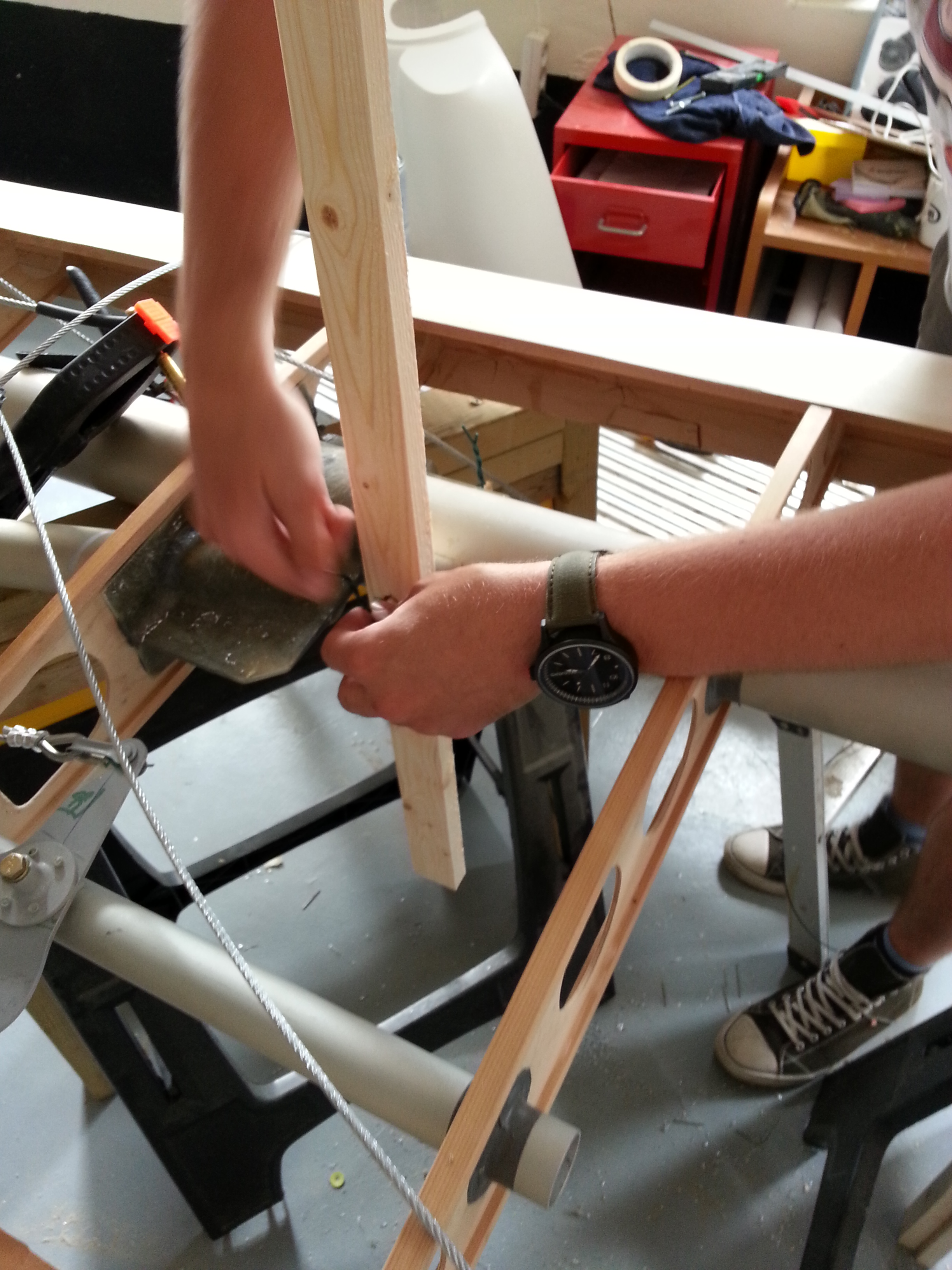
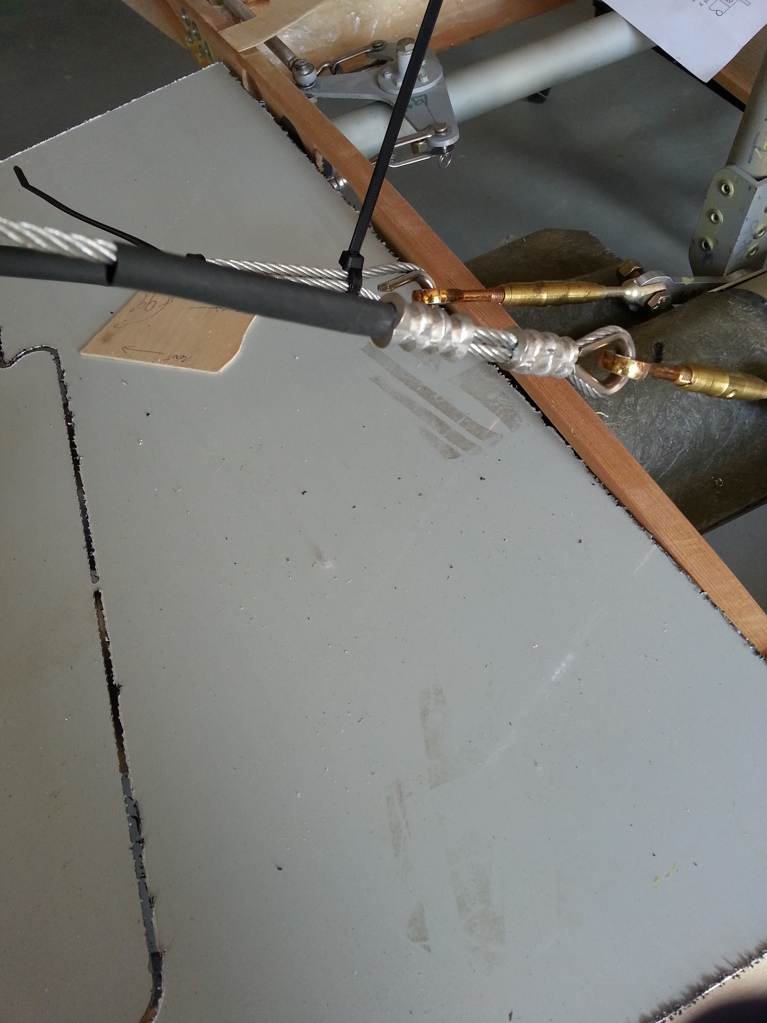
Using moles grips to gently hold the collars in place I cramped the first, remembering to have slipped on BOTH collars as well as the heat shrink tubing (you cant slip them on afterwards !)

rig2

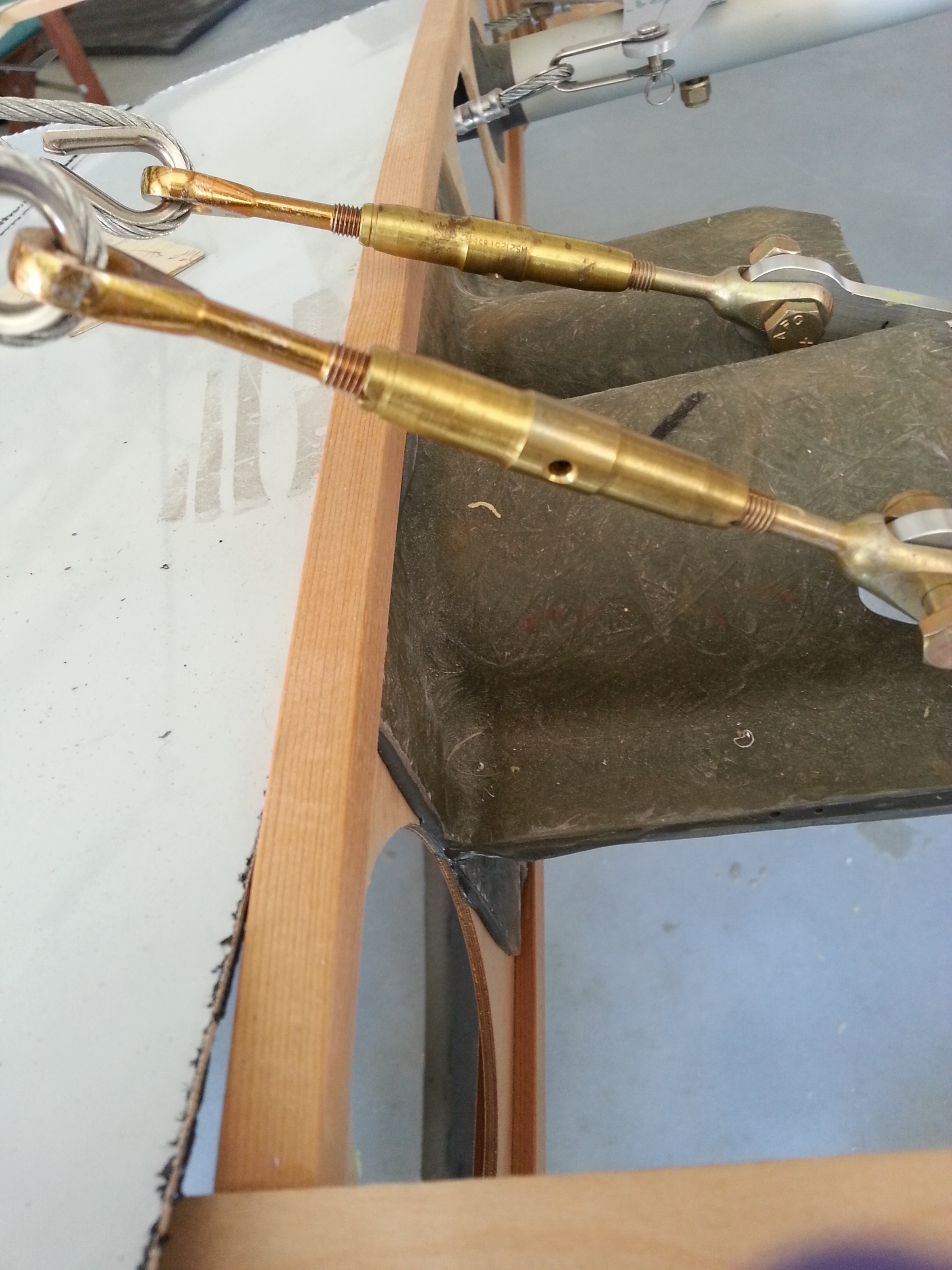
The first one went on very easily … and after a few turns was tightening nicely with still plenty of room for adjustment.

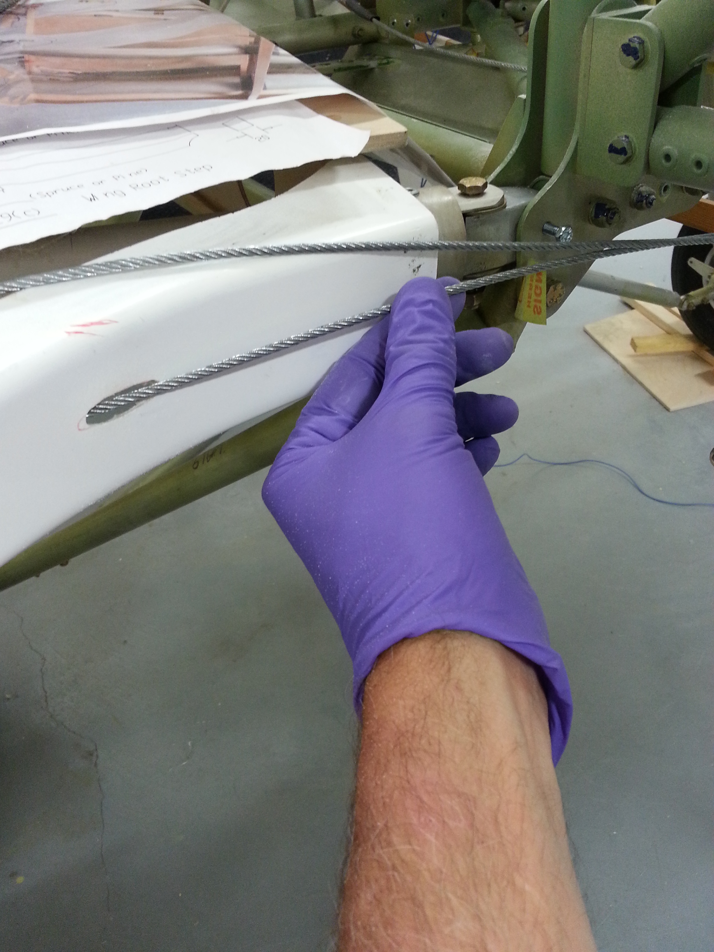
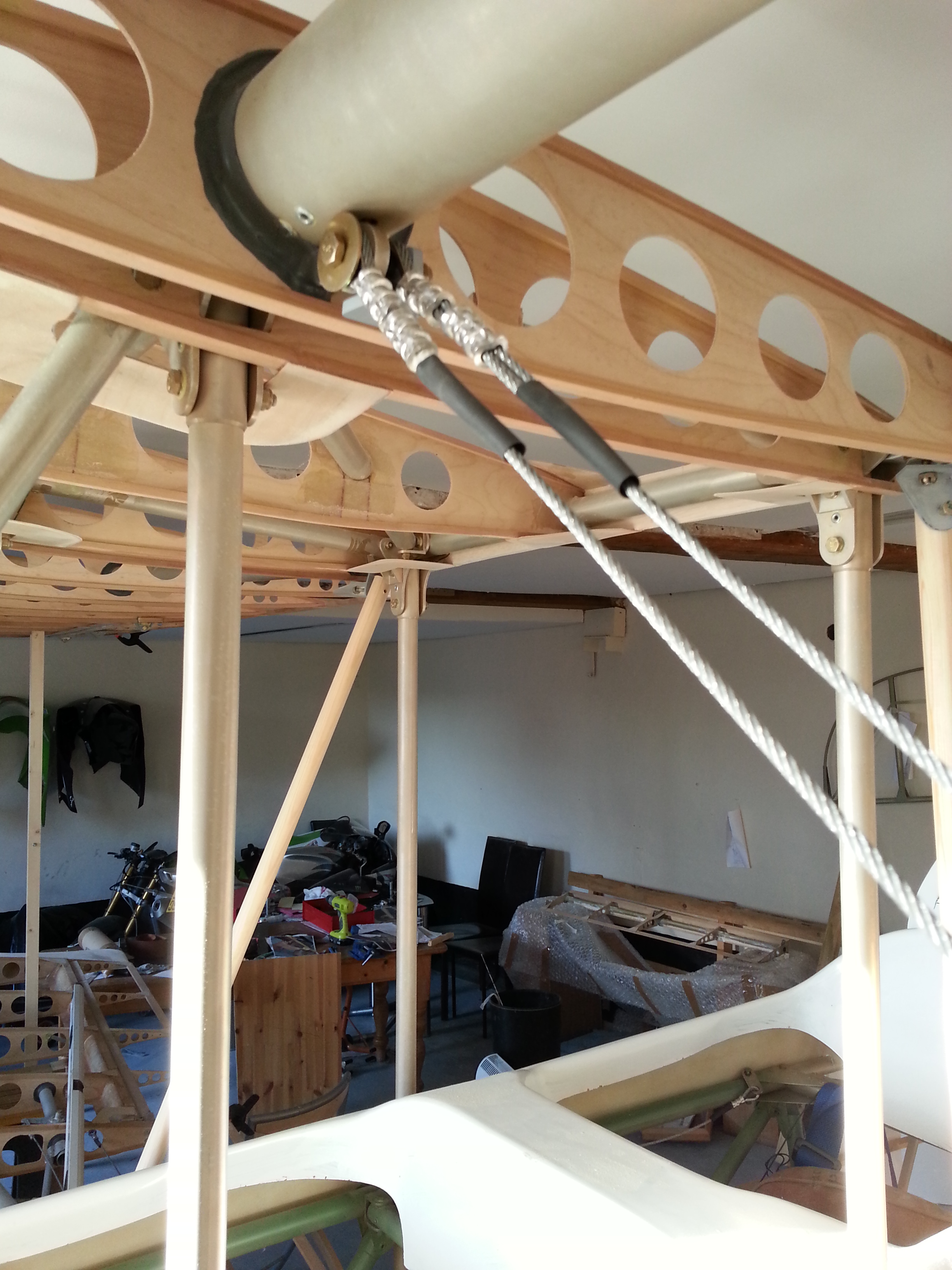
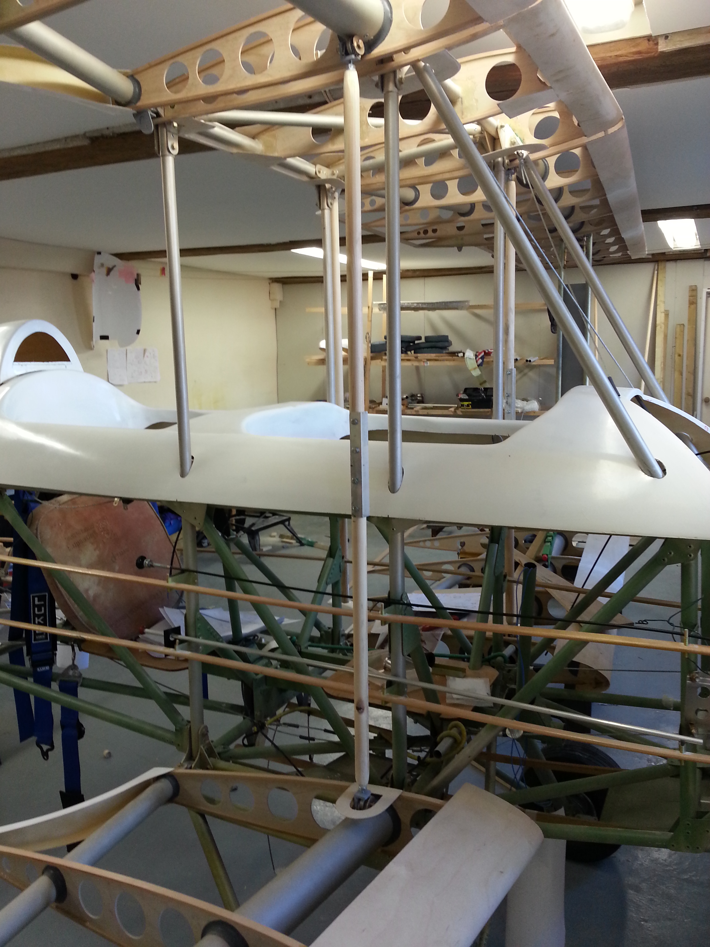
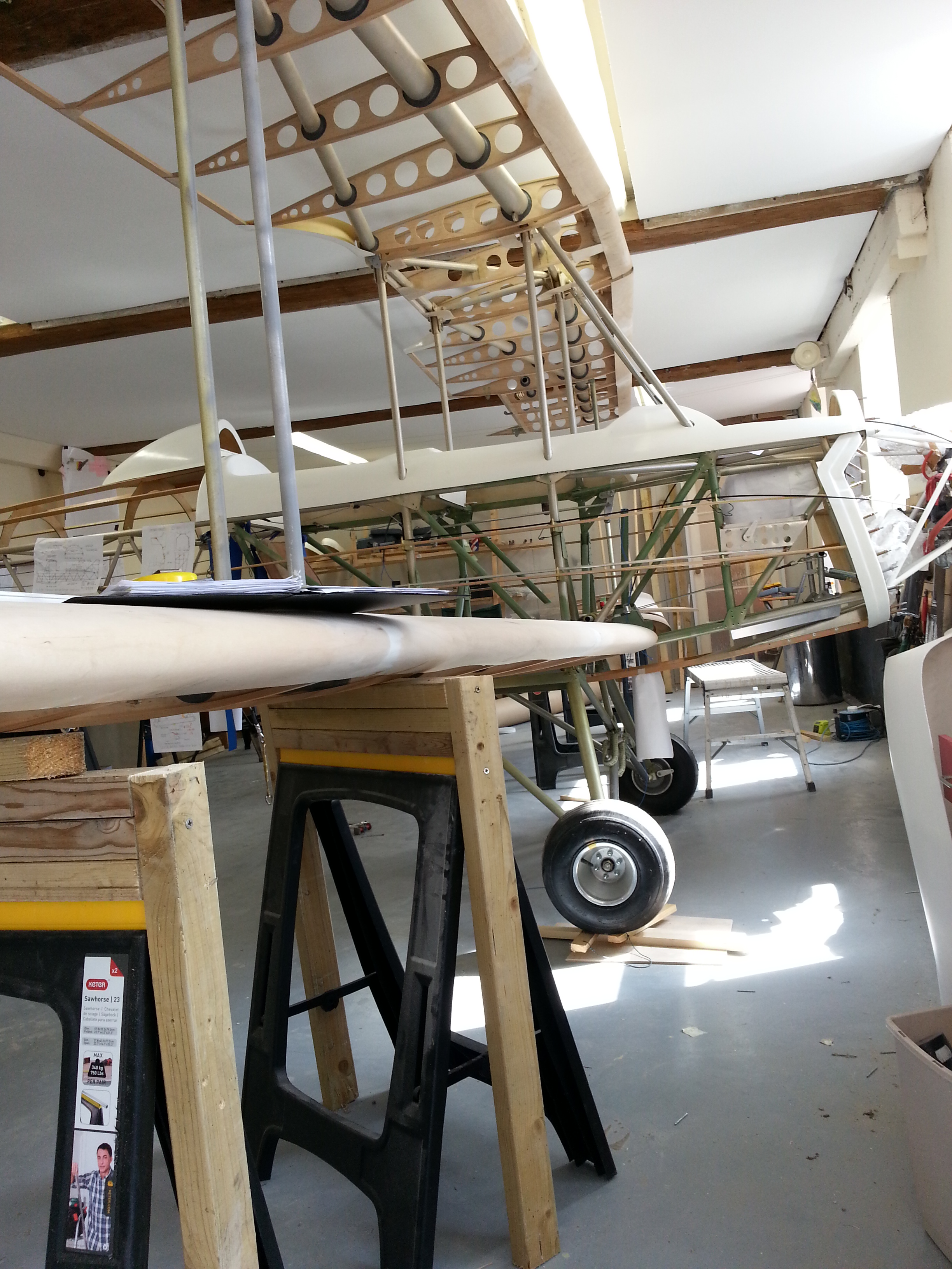
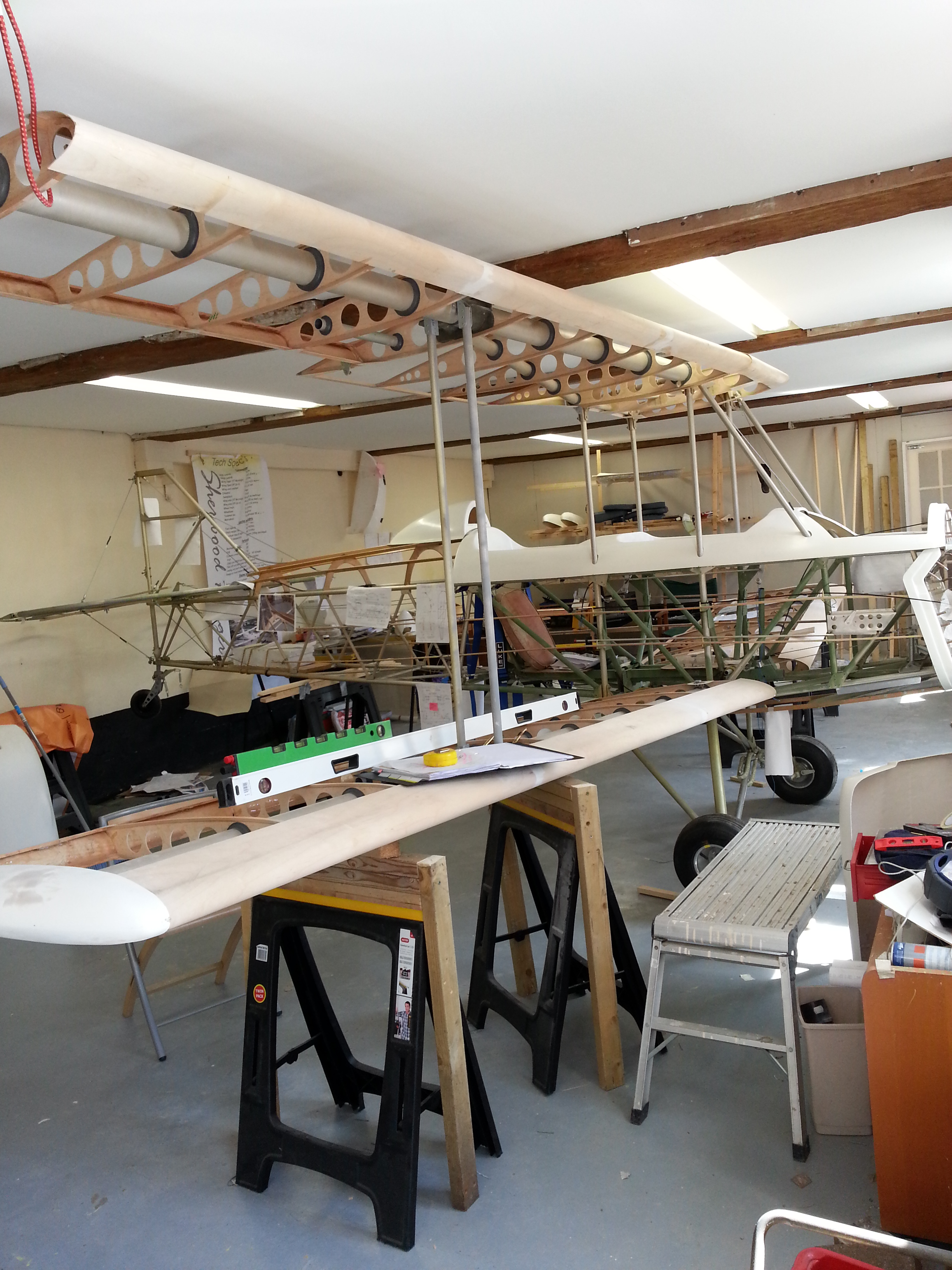
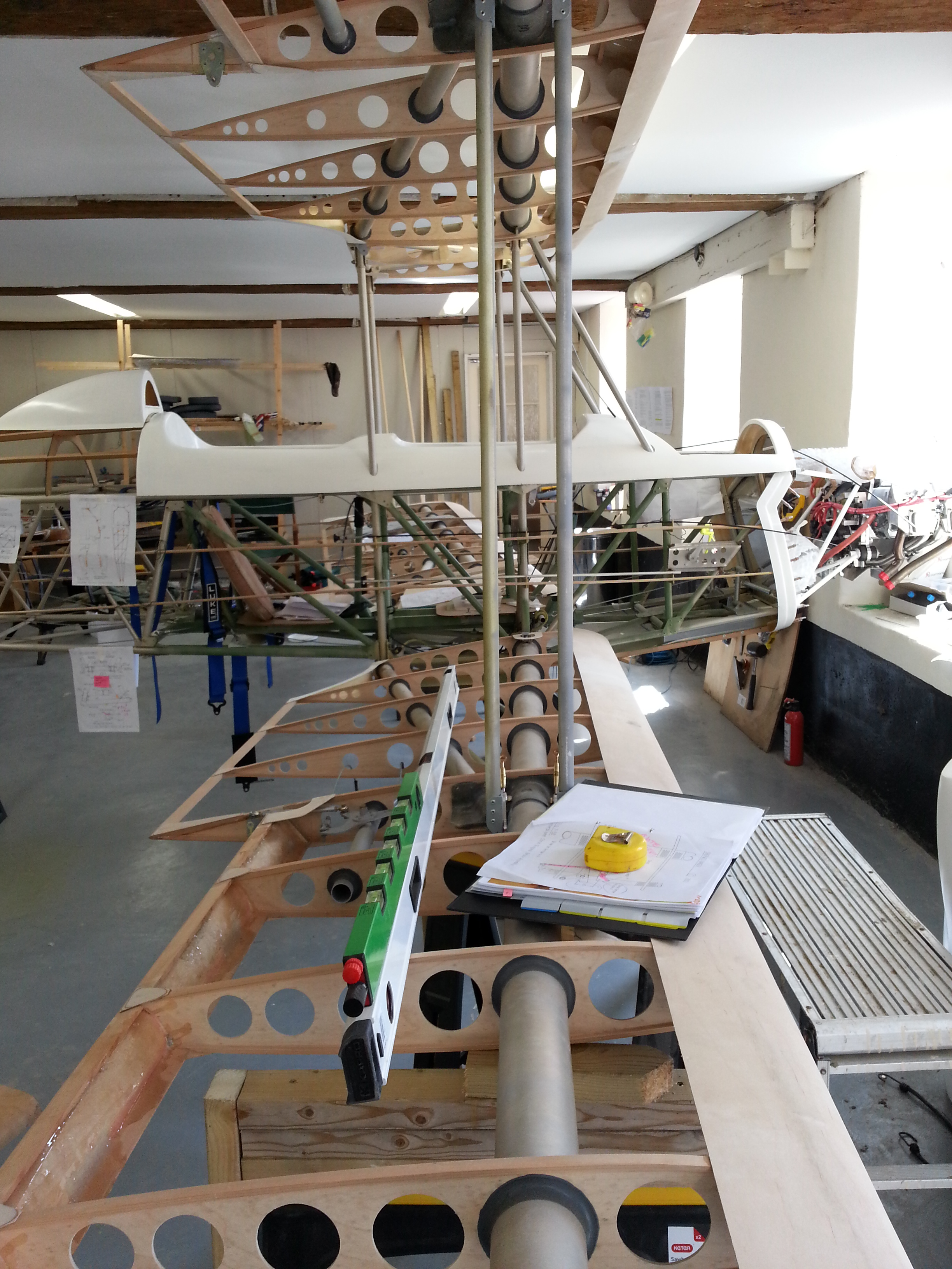
All four wires were then completed and loosely tightened in turn to bring a balanced rigid feel to the structure

rig 1  rig3


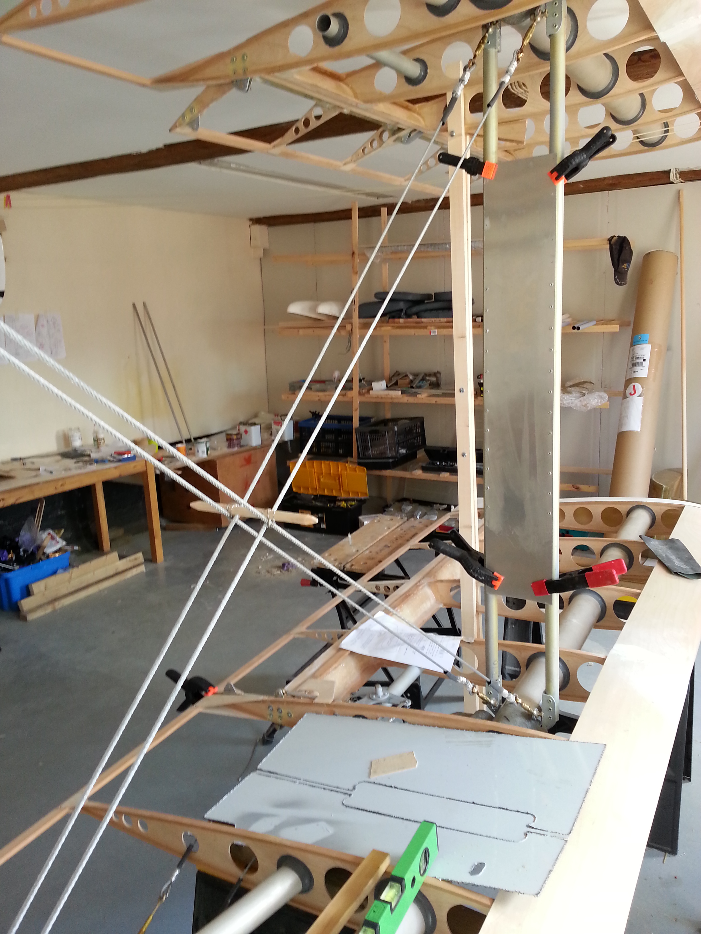
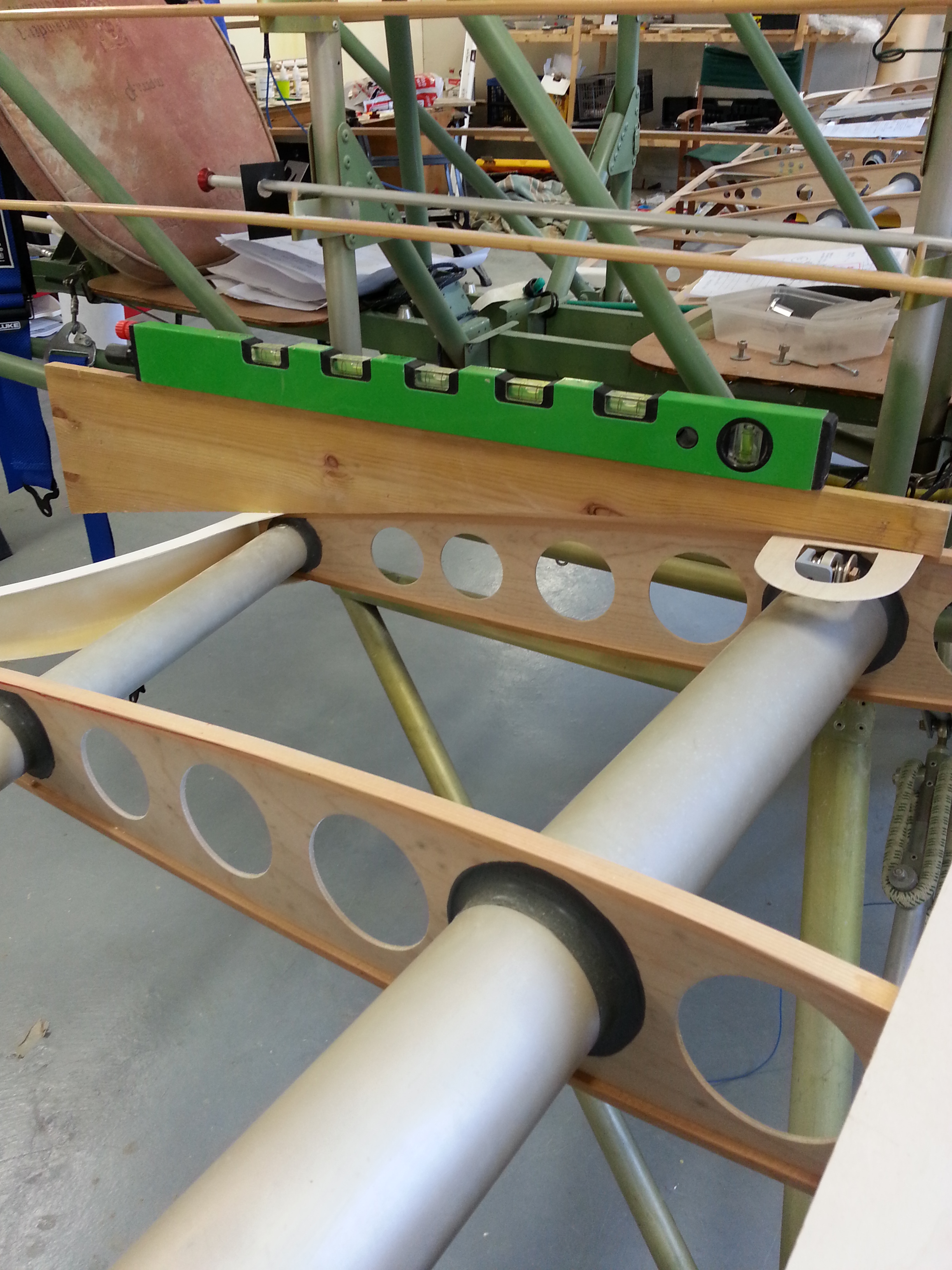
You will see you have a junction where each pair of wires cross. You can either use plastic/overlap joints or, an idea I got from flying the old Stampe (G-AYCK) and my mate John Graham … bind a bullet shaped piece of dowel wood in place which does the job nicely. Looking at the picture now it may be a little too long, but I can trim that back when I can stand back and look at it in proportion.

Aileron cable runs

A couple of visitors over from the UK this evening (Abi and Theo from one our companies system suppliers eFront). Had a wide eyed look around the ‘plane and setup .. both are up for a flight whe its ready …

Got cracking on the cable runs whilst I wait for the wing strut bolts to be drilled through. Decided to send these in to a marine shop locally as my recent efforts of drilling aviation bolt threads at right angles usually involves wandering drill bits, broken drill bits and lots of new interesting words !

ail cable run 0  ail cable run 1

The aileron cables runs will run through the trailing edge to allow as straight a run as possible. The inboard guides, prepared months ago are ready to rivet in place once I confirm a neat straight line.

With turnbuckles in situ at least I will get some degree of adjustment.

Strut Removal for Bolt Drilling

Benjamin – my eldest was back in Jersey at the weekend taking a short break from his new job at Williams F1 – now there’s a fantastic job !  so I roped him in to use his engineering skills and help me remove my lovingly build and secure struts to prepare for drilling the bolts. The removal of the bolts turned out to be far easier than I thought and, with a little gentle persuasion, they slipped out (lower one first) and then the strut simply dropped down and then out to the side.

The large bolts that go through the spar also pickup the turnbuckle shanks and run through the offset mounted strut brackets. This gives the strut a sort of toe in effect towards the nose but means that you cant get a washer/nut arrangement on. Although all its load is in shear the bolt needs obviously to be securely retained and this is achieved by drilling through the bracket AND the bolt shank and securing with a 314 bolt.

Web bolt 1   Web bolt 0

To prevent the top wing collapsing it is supported both at the root and the tip BUT also by two additional 2 x 1 wood braces, bracing it directly to the floor and then in addition (as I don’t want any movement) a replica sized strut made from 2 x 1 wood, that locates with pegged dowels in place of the now removed strut.

web bolt 2

Having had fun and games trying to drill aviation bolt shanks before I plan to pop this into a local marine engineering company who will be able to get a really accurate straight hole without the bit wandering and ruining the brackets !

Started wing bracing wires

There are a lot of things coming together at this time with the wings bracing, struts and jurys and webs and hinging and drilling etc


The wing drill kit (a set of tailored extended drills and reamers and guides have been sent over by Paul and Ivor from TLAC and having walked them through with the words in front of me it helped a million times going through it with Paul on the phone then my resident engineering expert Mike Fleming. He obviously speaks pur ‘Paul/TLAC’ language and had it all sussed in minutes …


We will walk through again prior to actually drilling but Mike has offered to be on hand on the day we finally cut !

In prep for this we need the wing bracing wires loosely fitted and ready to tighten.

wires 1    wires 2

These added reminds me very much of the Stampe days (G-AYCK) that I flew so much … immaculately maintained steel wires and used to whistle in a dive in flight … great stuff !

Just waiting a few more thimbles and I can do up both ends and then take up the slack with the turnbuckles

Jury strut

Busy weekend flying through Caen(for customs) then on to Paris (Toussus) … manicly busy with both runways active .. nice formation take offs and both turning right into an ever busy circuit with people joining at the same time … drop dead weather though once above the fluffy white stuff !

Jersey does look stunning on the way back – La Rocque harbour (S/E corner)

La Rocque

Managed to get the first upright of a Jury strut completed and breaking to allow removal. Second one now done. Not happy with the light alloy lower bracing bracket I’ve made … it cuts and shapes easily but is simply far too thin … will pick up some beefier alloy today and use the one I have created as a template.

Jury 2 in place  Jury 1. in placejpg

Propped starboard wing to prepare for removal of strut to allow the spar bolt to be drilled through.

Strut – bracing

Worked on adding the strut bracing sheets last night. Make sure the strut bars are closely seated then clamp the first sheet so that the pilot holes sit mid way on the alloy tube.

strut plate 1

Then add cleco’s from the centre out as you drill successive holes.

strut plate 2    wing strut 3

Spinner – First Cut

Started the cut and tailor the spinner to seat on the top of the propeller boss/flange. This involved shaping a paper template around the propeller and then using that as a guide to mark exact opposite points on the TLAC supplied spinner to cut undersized slots of opposite slants.

20140601_134430  20140601_140129  20140601_140335

These are being slowly opened up to make sure that I don’t end up with a large gap around the prop edge.

Getting there – added protection tape around the prop as I didn’t want the sharp edge cutting the varnish. Also had to shorten the spigot slightly to get the spinner edge to sit in the channel backplate.

prop spinner


16:00 Sunday 1st June – I have a Bi Plane !!

Having spent weeks preparing the wings for the moment I could trial fit them all into position …. it seems to have suddenly crept up on me !

With the lower pair trestled and secure and dihedral and incidence set Keith and I rigged a support for the top wing and tips and then lifted the starboard wing into position, fitting the temporary 3/16″ bolt in the rear joint and bush.

20140601_132320  20140601_161206 20140601_152531 20140601_152524

We then swung the leading edge forward and lifted the wing to allow the two strut bars to settle fore and aft of the main spar. This was a tricky moment as the struts should have been finished in situ, NOT Before !

The top wing, in position, was a matter of inches from the barn roof so I couldn’t check the dihedral with my lower wing dihedral board (This was 3 degree anyway). Having made some very dodgy mental calculations of potential diherdral based on differential gap over 5 ribs I opted to make a top wing dihedral check board of 1 degree slope. With the struts firmly in place between the wings and the central main spar bolt located through the alloy mounts for the turnbuckles at the lower fitting, the same was set at the top wing fitting.

20140601_153210 20140601_161136 20140601_161115 20140601_161101

The same routine was repeated for the Port wing and in a metter of minutes we had all 4 wings located and suddenly it looked like a LOT OF AIRCRAFT !


This is now ready for the equipment shipped out from TLAC , a tailored dolly and extended drill bit and reamers to allow a tailored joint to be drilled to set the angle in the fuselage body.

Blog at WordPress.com.

Up ↑