Re-cover rear battery access panel

The easy access panel came in handy again and hopefully the last time I will need that for a while šŸ˜€

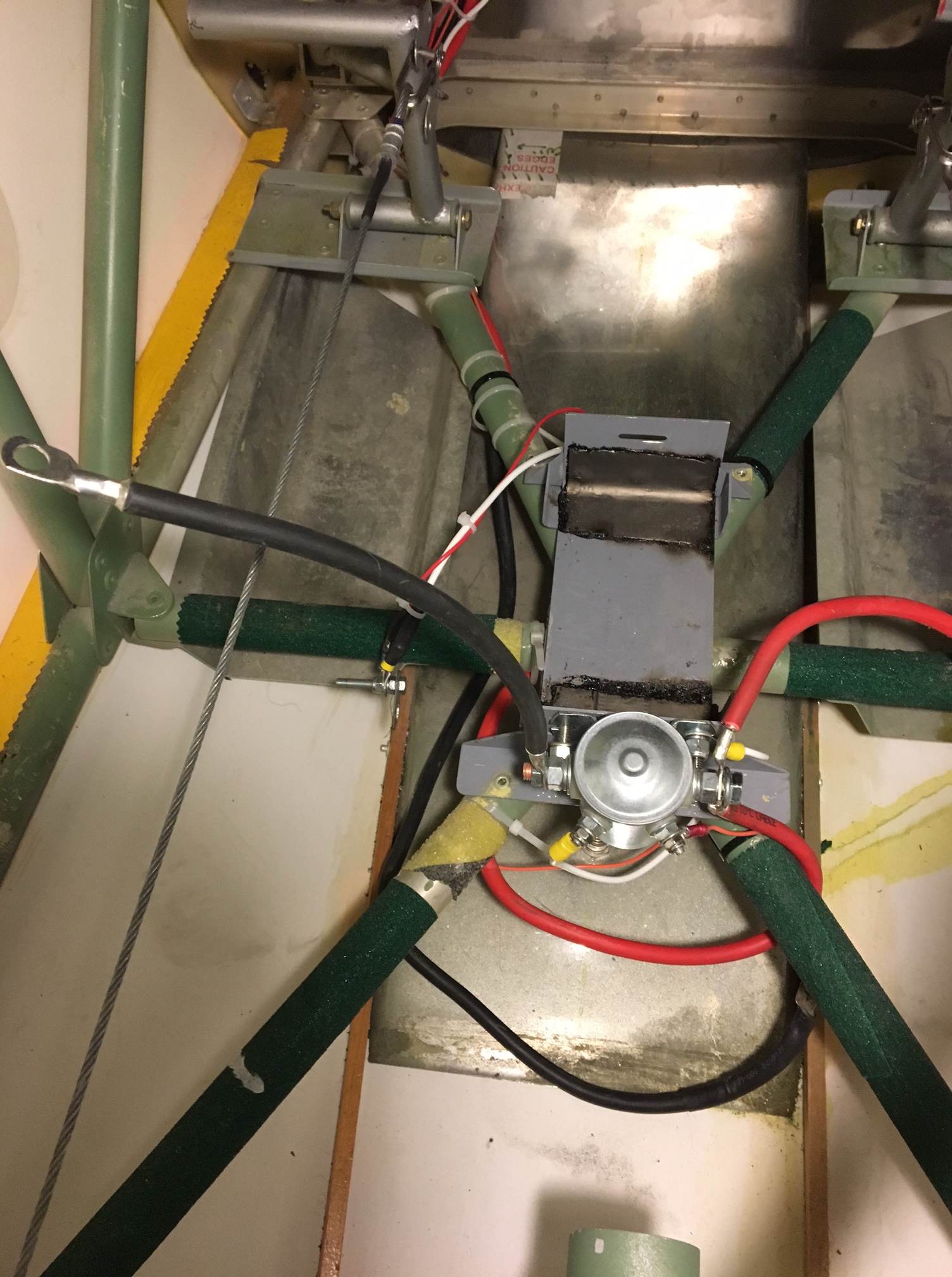
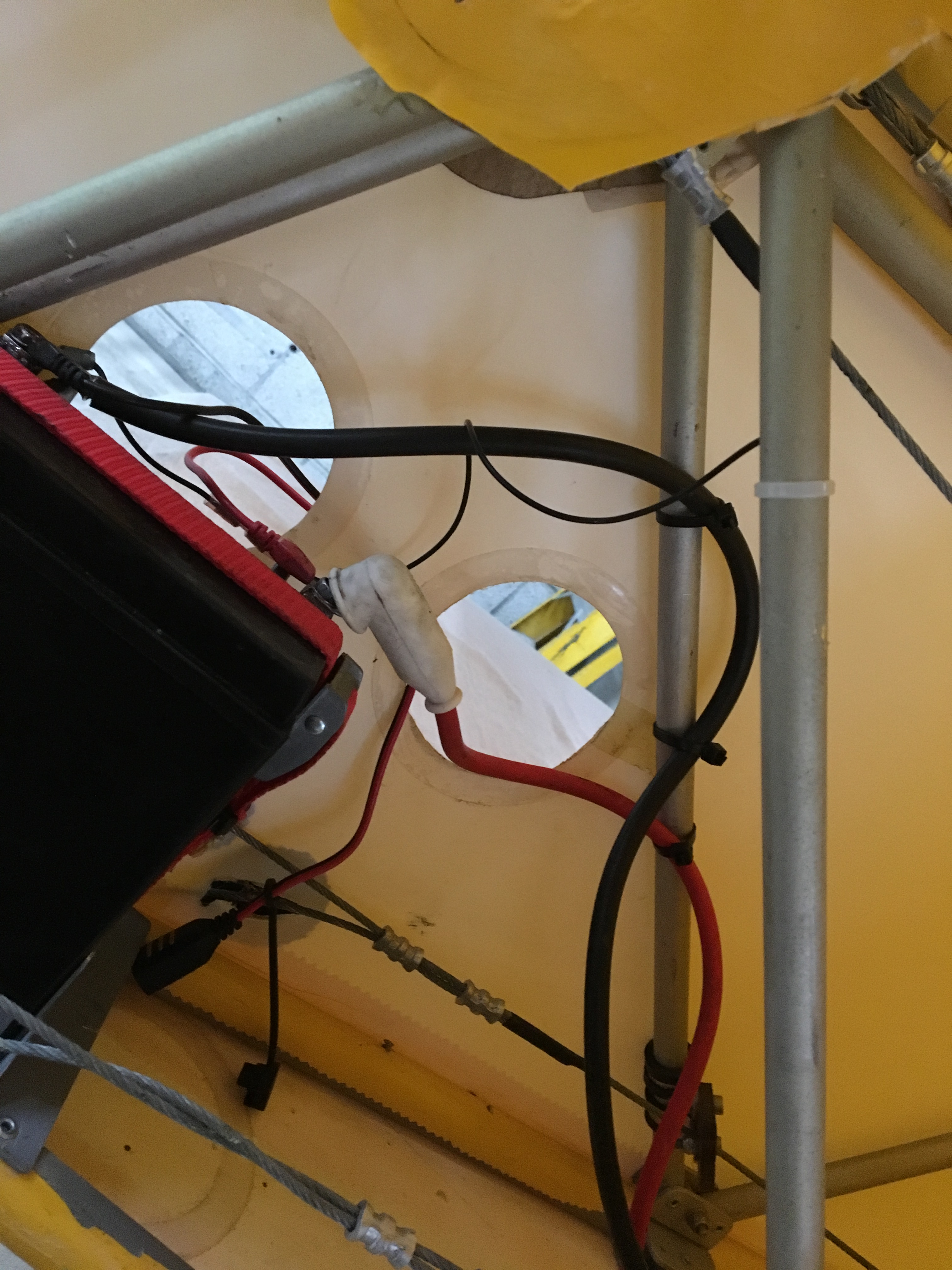
So – it turns out that moving the relatively small Motorcycle battery all the way to the back was

  1. Great for weight .. needed ZERO ballast to fly her straight off the plan !
  2. BUT hopeless when you expect around 5m of cable to still give you suitable start grunt at the front !

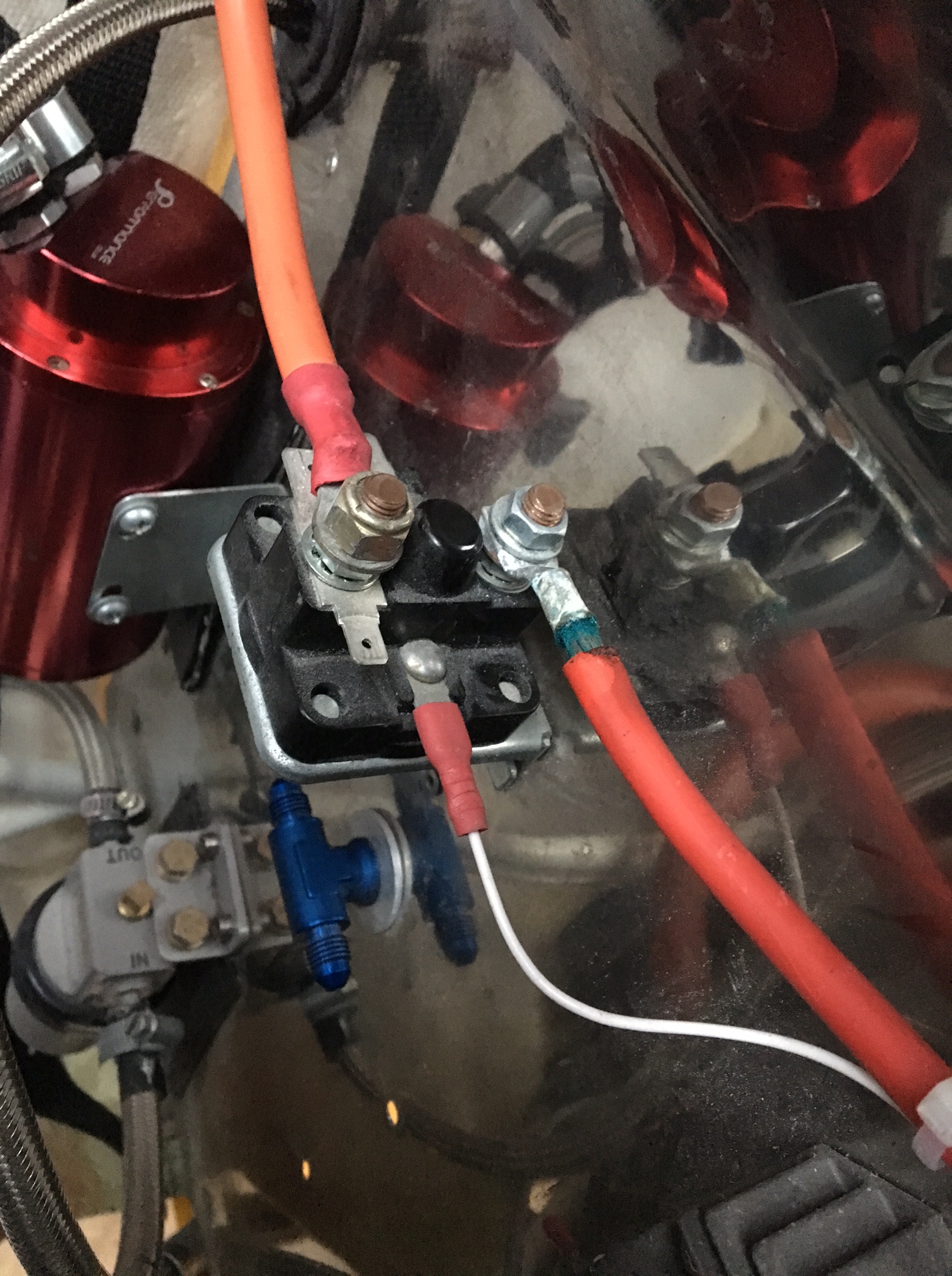
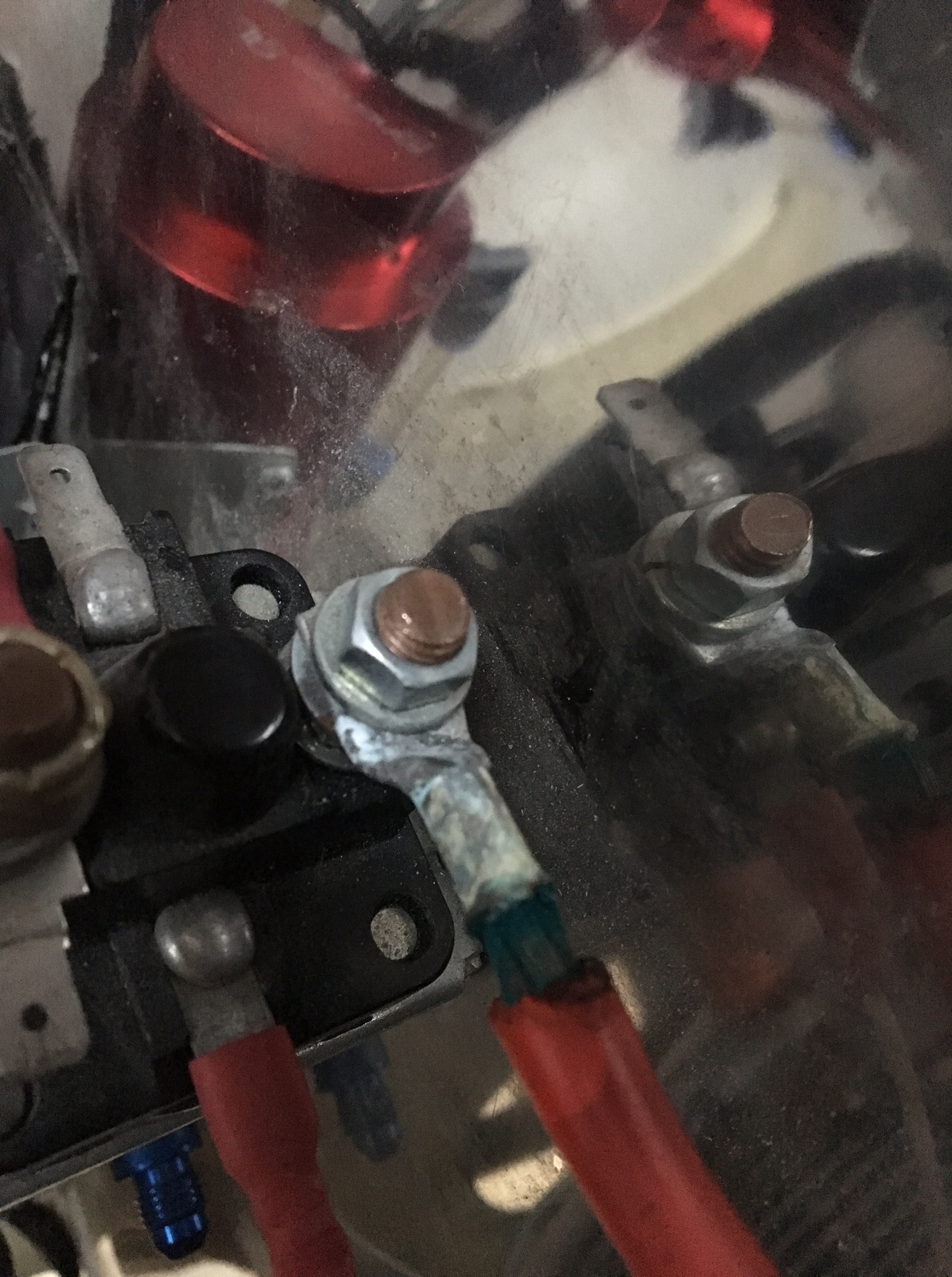
the solution was to re-add the original (now spare ) battery at the front – already had then TLAC mounting plate in position..

Then connect the two in parallel and bingo .. it turns like crazy …

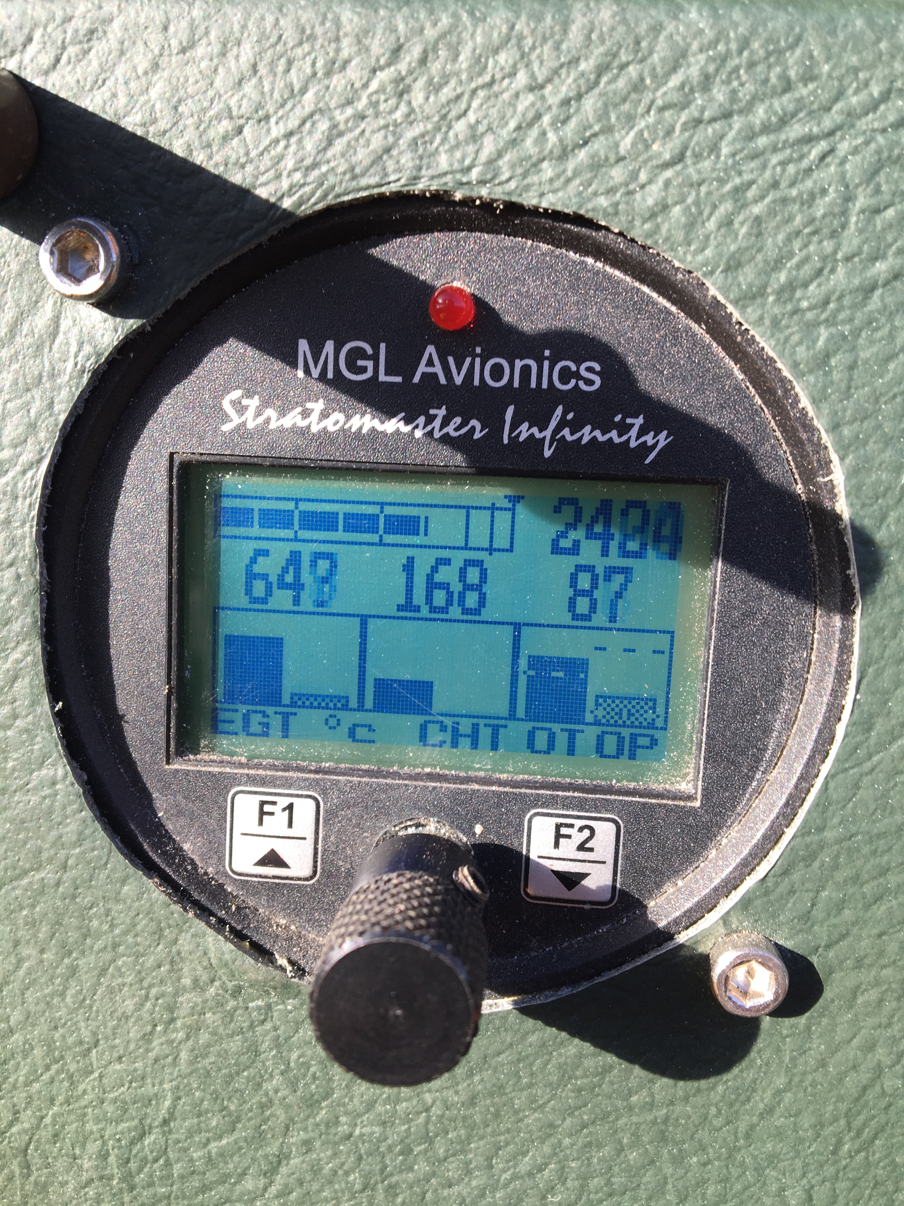
Amazing difference yesterday (27th January) and again after a 20 min run .. leave it for a few mins to cool down then a hot start .. burst into life instantly with barely 1/2 a revolution

img_2100img_2095

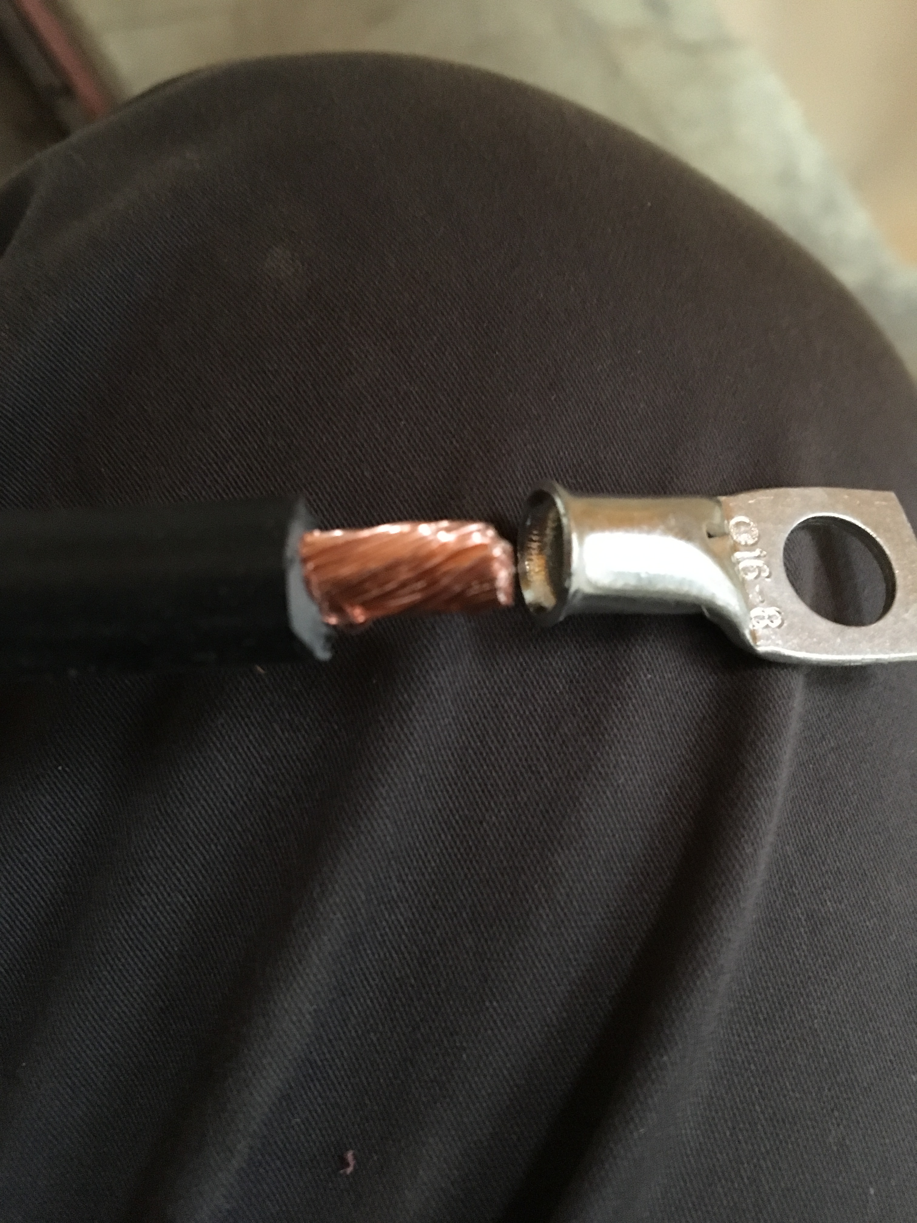
Bear back to allow a nice snug fit against the connector

img_2097img_2098

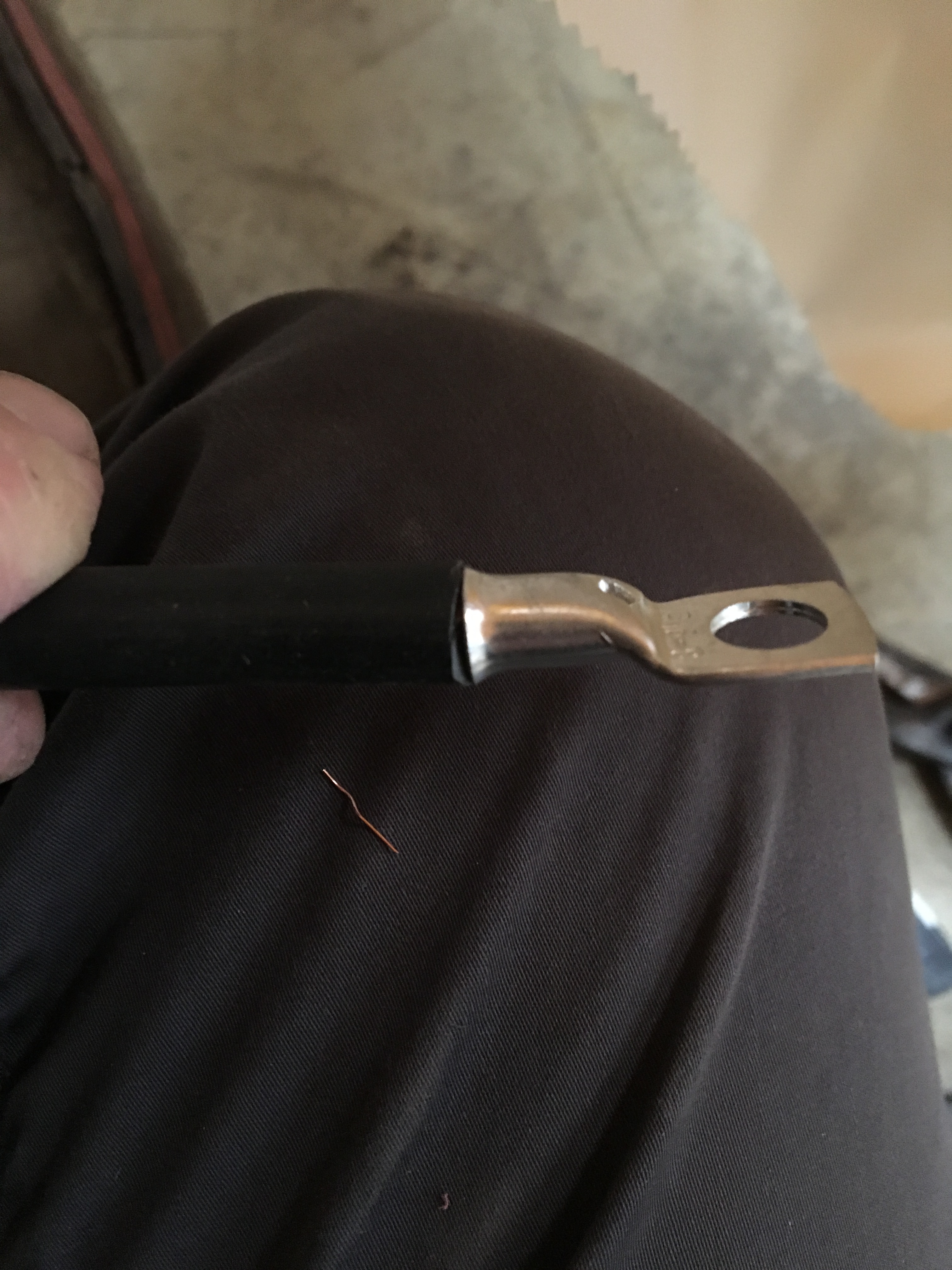
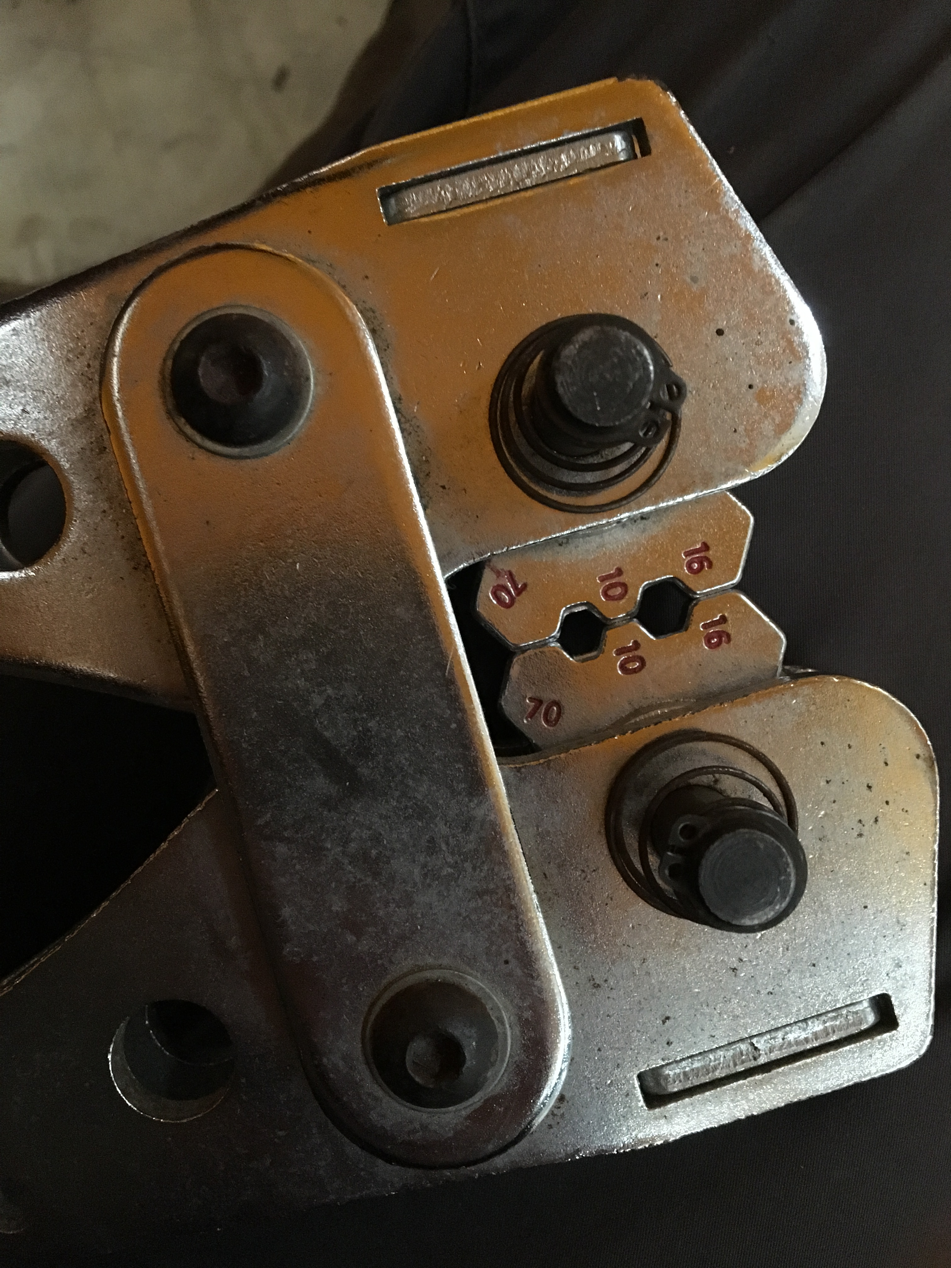
Pick the correct size crimp for the ring connector (16)

img_2099

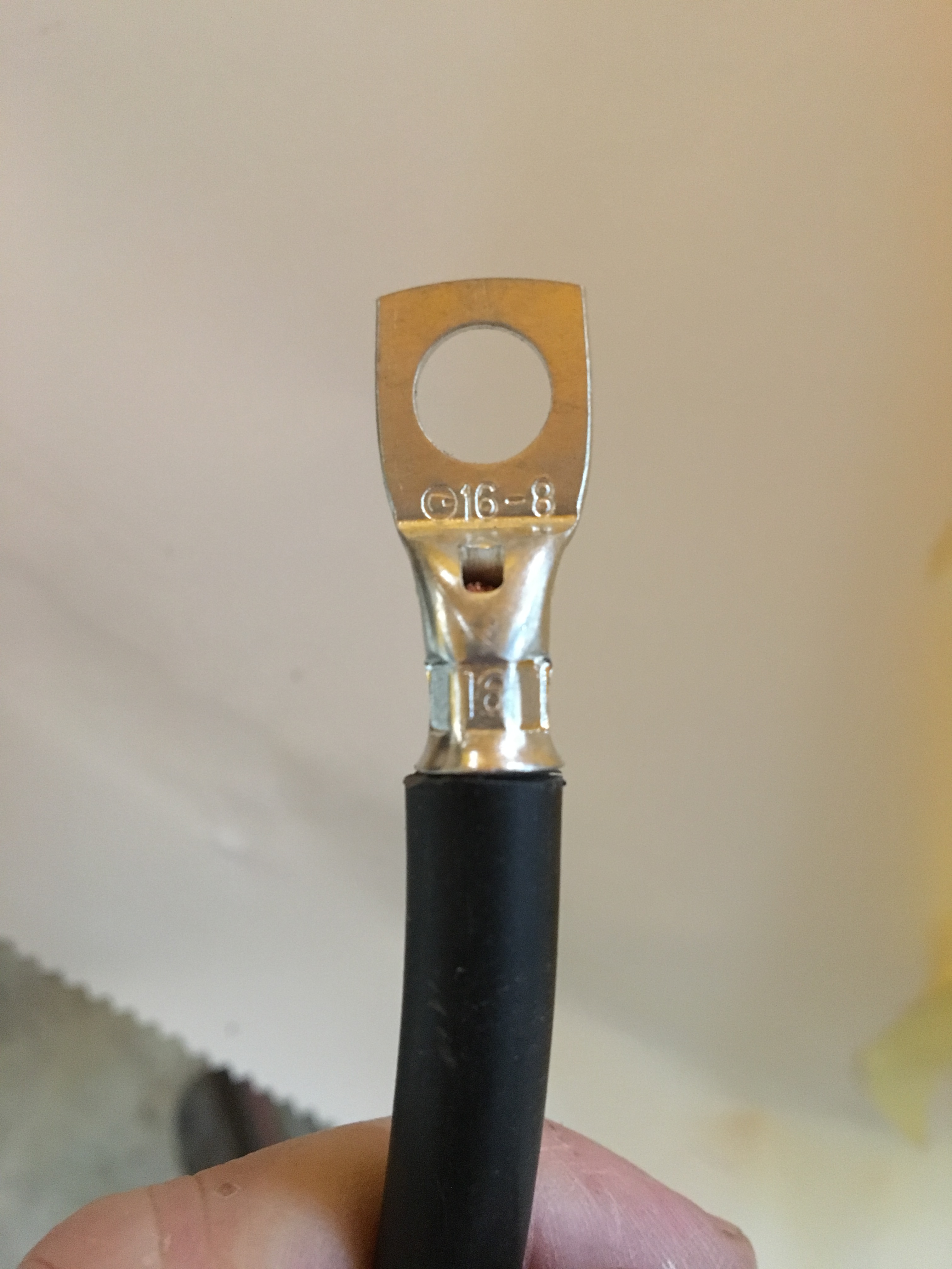
Neat auto stamping of the crimp size confirms we used the correct connector for the 16 size crimp .. what a clever featureĀ img_2101

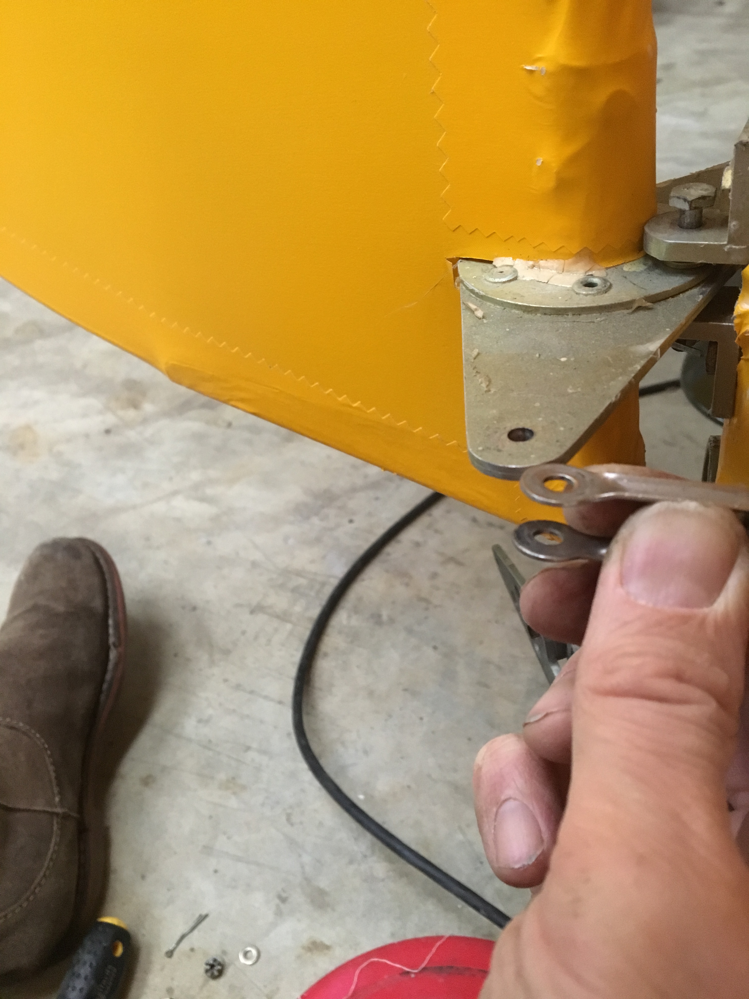
Re cover time – need to undo the rudder connection

img_2102img_2103

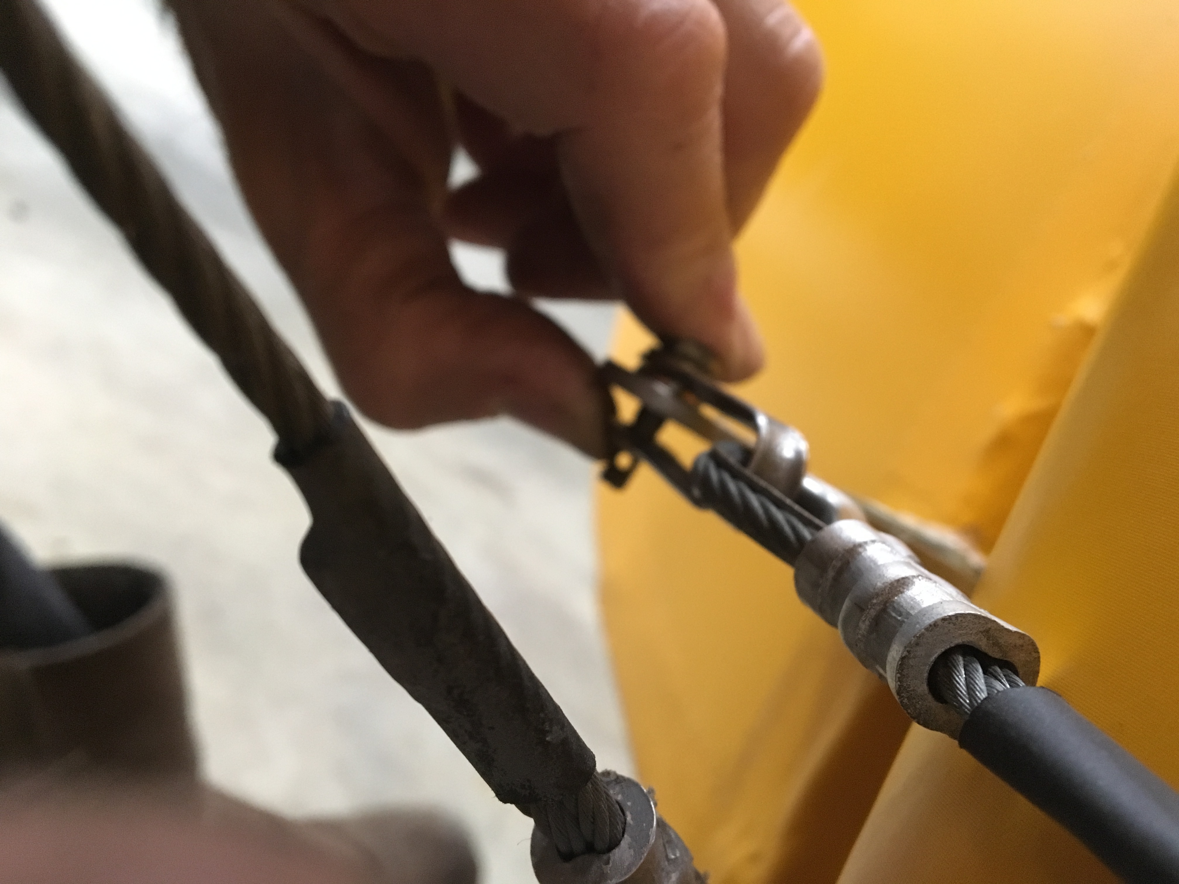
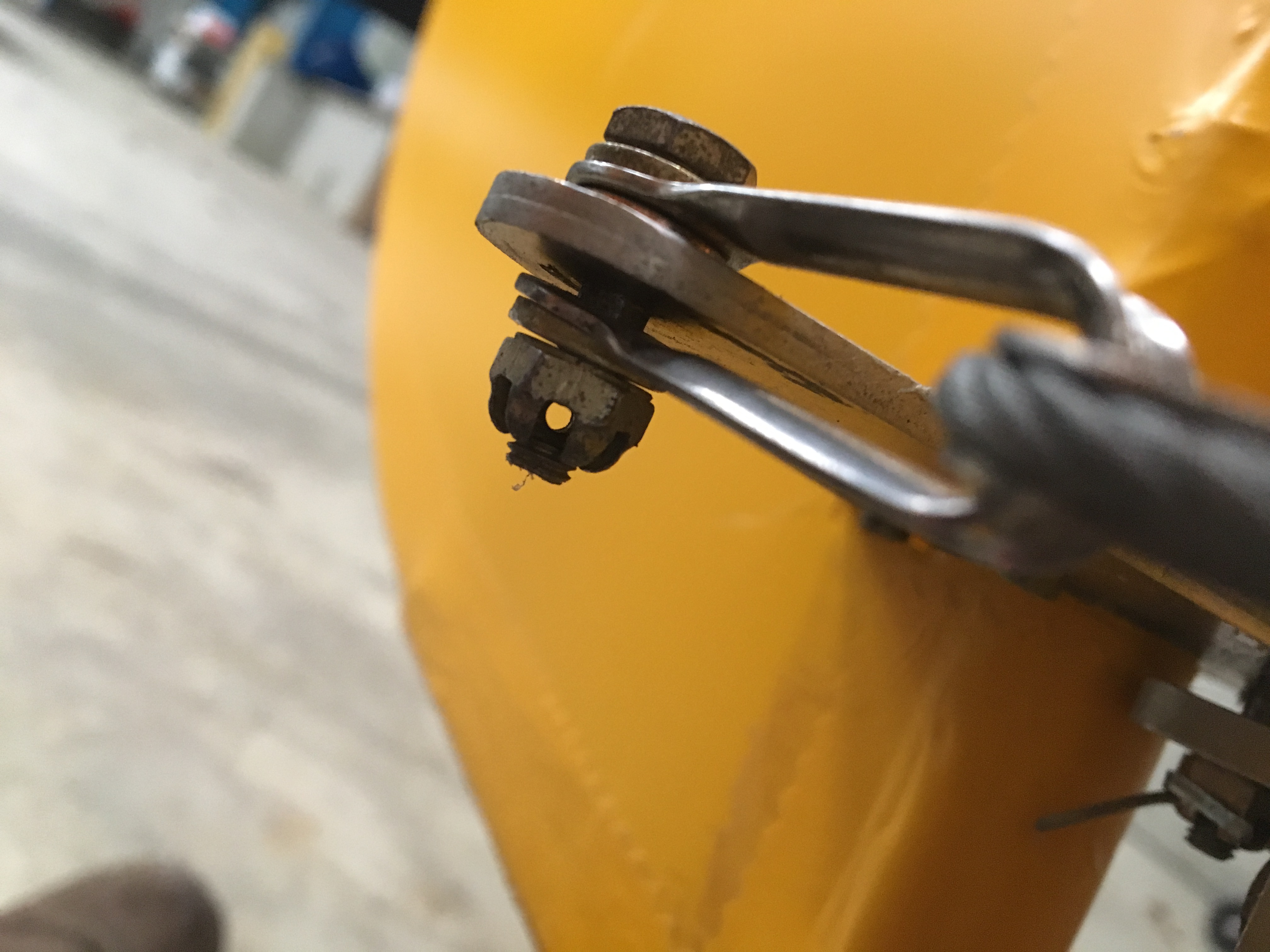
Align the castellated nut to accept the securing split pin

img_2106

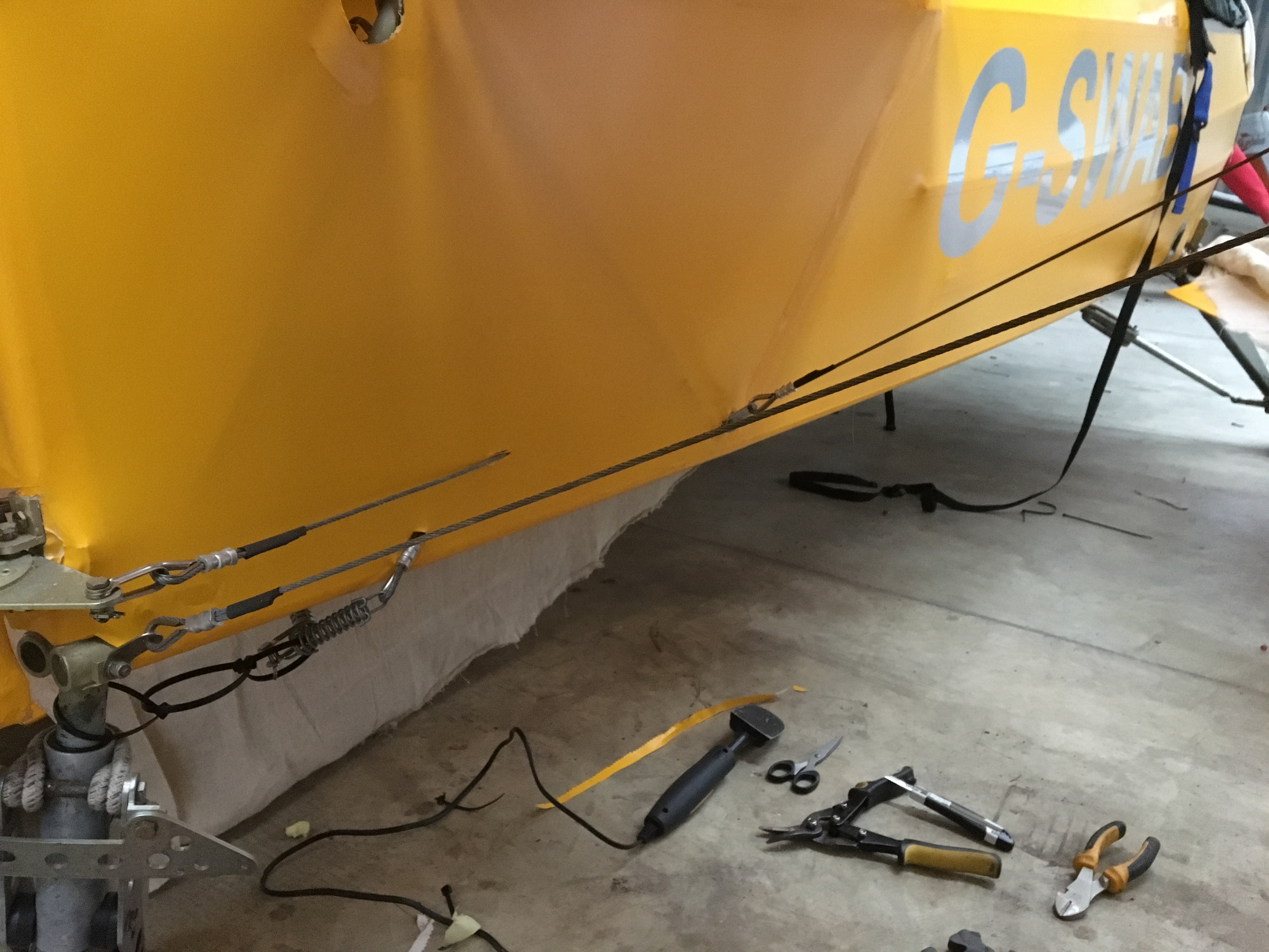
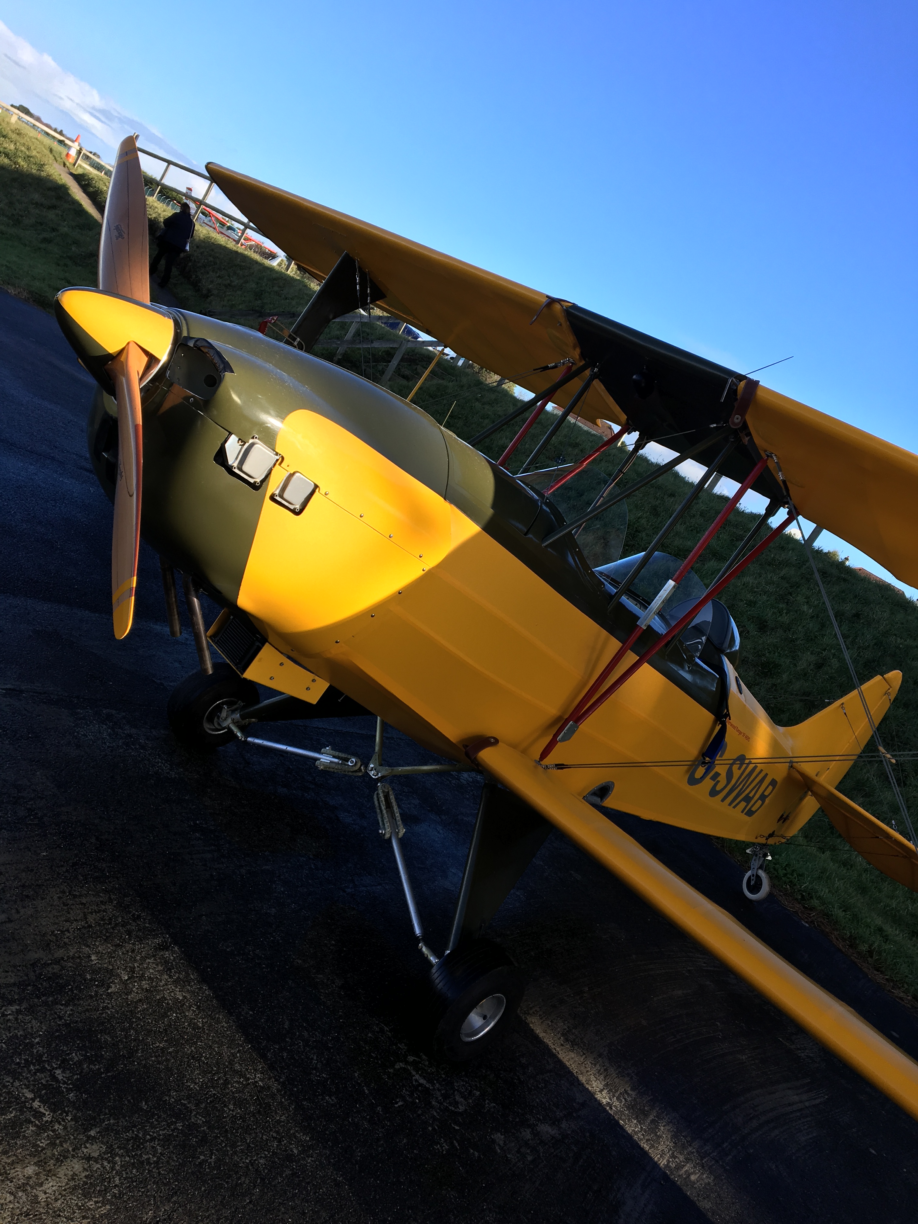
As the whole turtle deck downwards was covered in one continuous sheet I clearly didn’t want to recover ALL of that just because of the rear battery access. So I cut into the Oratex just rearwards of the 45 degree sloping alloy tube support … just rear wards of the ā€œGā€ reg sticker in the picture above .. allowing about a 6ā€ overlap.

The overlap was glued along with the down bar and left to dry overnight. Next day this was ironed into position so making a secure point and leaving a rear section from that point to the rudder post open.

A new piece of material was cut and prepared and glued and fitted the following day to cover this large access panel under the starboard elevator lower fuselage. If required, this section can be removed without affecting the integrity of the rest of the side. In fact you could almost pre cover like this as it would make the single piece sheet a little less unwieldy as it would be that much shorter !

Engine retest – post putting two batteries in parallel

Just awesome starting now …

Wheeled out into blustery conditions but sheltered by the hangers ..ran for 2×20 mins with RPM up to 2400+ for extended periods

  • img_2067
  • img_2089
  • Temperature maintained around 90-102max after some 40 minutes of running
  • img_2088

Switched Oil pressure to PSI .. to make it easier to keep an eye on reading 34 at just over 2400 RPM

January 2017 – Ignition – BINGO !

Well….BINGO …meaty the help of a couple of very good solid knowledgable friends .. Mike (Fleming) and Chris (Sparrow) we now have a truly neat and robust solution .. And tested it this evening …

The original location of the battery (front centre between the P2 legs !) was moved at LAA suggestion which was

  • Good – to remove any ballast at all as the aircraft came out spot on with the battery at the tail
  • Bad – as the cable run to the solenoid so was nearly 5m ! Which .. With a relatively small motorcycle battery turned out to be a real struggle

The solution .. Thank you Mike ! …. Was to reinstall the front battery .. It’s pretty much on the C of G and then wire them in parallel and then review ALL crimped connectors

Then around 1700 this evening mags off, fuel off, throttle set, turns brilliantly !!

Now just need to neaten all cable runs and angles and ensure all booted over joints … Then

GET FLYING AGAIN !!!! Feels like way too long … Good powered engine test first to ensure cooling is in good shape then power climb awaits along with unusual attitude and handling then LAA paperwork off


January 2017 – Ignition review

Crikey .. January has come and is nearly gone but I have tried to get time to work on the starting problem

With the great help of local friends Mike Fleming and Chris ex Jersey Airport we have slowly gone through the system back to front … One quick eliminaton was to connect directly to the front solenoid and effectively jump start her .. This proved that the engine, starter and associated bits were all functioning properly.

It also proved that the problem lay somewhere between front and rear !

I had worked in two solenoid and so we el inmates rearwards from the front… Having first run a dedicated full length black earth from the rear mounted battery to the rear engine bolt. THis meant we wouldn’t have to worry about any earth connections.

After much tooi g and front and using a booster battery to test we could guess that the power drop over the necessary full length body cables (to pickup rear mounted battery) was too great and so we had to find some way of staining the boost and yet still retain the rear mounted battery.

Mile then hit on the idea of leaving the rear battery in position but also mounting a second battery up front in series. This would have the effect of

  • Boosting the supply for start and
  • Providing a high degree of contingency

imageimageimage


Also .. Having reviewed and re-crimped front to rear we discovered that the very front connection to the engine start solenoid had discoloured and had signs of poor initial connection.

This was cut back until we saw fully clear – non discoloured multi core copper cable. This took about 15mm back then it was fine.

The current plan is to retain the rear battery due to LAA spec and weight and balance. Then put the second battery in the original front mounted tray. This will mean we have only around 1m of cable to run to the starter .. The connection should mean that we have two in situ batteries that charge and provide both start and normal avionics support.

Blog at WordPress.com.

Up ↑