Busy night last night

Had my engineering mentor down with me .. Good Mr Fleming …

he took me back to first principles of solenoid connections and also we stepped through the initial test wiring I had created.

Turns out I had missed a wire ! So checked it all through, drilled the bulkhead for an additional earth wire .. Located a suitable chunky bolt on the back of the engine and attached earth cable. Ran it through new grommet end hole and secured along the way.

image image

Temp attached started cable and flicked mains on and pressed the starter  ! Bingo .. We have life and a quarter turn of the prop !

now to push on with instruments connectivity


Lots of things being worked on at the moment

With the LAA flight test forms about to go off there are lots of bits to complete …

FullSizeRender_1  FullSizeRender_2

Heat shrinking sleev to protect power lead … grommented through bulkhead

FullSizeRender_3

Solenoid fitted to battery tray

pic 3

With recent incident I read and the factthat I have put the wheels on and off around 3 times so far another check that all 12 bolts are tight … checked ok ..

pic11

Both footrests prepared ready for fitting once i confirm the lie of the material

pic10

Covered dashboard having fittings re-applied ready for wiring up

Reckcon lower body and sides will take about 3 evenings

Weight and Balance and C of G – Late night weigh in :-)

After all that covering .. time to re-weigh and see where it all settles out in terms of weight and balance.

Got 125Kg on each wheel and 10Kg on the tail. So all up it’s not looking too heavy.

pic 1  pic 2

EMPTY – well allowing for me as a 75Kg Pilot sitting in P1 AND with a tank of say 40 litres of fuel the CofG comes out at 185cm from my datum (rear of the prop flange) ..the TLAC stated CofG is between 180 and 190 from that point ! so smack on midway ….

pic 1

Trouble is life isn’t that simple and you need to cater for the normal ‘flight operating window’ ie taking off with a load of fuel that then burns and changes the CofG

The ‘trick’ now is to use the LAA template to work out the worst case forward and worst case rearward CofG points. If fuel is burned off to say 1/3 of the tank the CofG moves rearwards by about 10-12 cm ..I am going to cross check this with Paul to make sure my figs /maths are correct as ideally i do not wish to put a chunk of ballast in the nose 🙂

Luckily the P2 – Passenger is pretty much dead on the CofG so doesn’t majorly affect the balance point.

Dashboards and struts and footrests

Finally got a browser that works ! Firefox …

Dashboards have been worked on and are both now fully covered in the green leather i got. Holes have been re-opened and now starting the wiring up process. Lots of handshake fly leads to connect up.

The fuel sender has come straight back from the guys in Norfolk from repair so ready to calibrate


Been a very very busy few weeks …but ..managed to keep moving on ..

With work going crazy and flights tobe made toLuxembourg (a very very long runway of 4k+ !) and last weekend Paris/Toussus .. I have finally managed to get back to some work on the Sherwood.   I have made so many lists of things that need to be finished off … so this session has been lots of those … struts covering (decided Olive Green would contrast the predominance of cub yellow  !) … electrics cabling from battery through the bulkhead to the solenoid …   Brake turnbuckles…. re doing some top covering (more on that later) …   Also, post the LAA recent article ..a full re check of my 12 wheel nuts for tightness ….    

FullSizeRender pic 2

Wiring and Finding Pre Covered Oratex holes !

Oratex is amazingly strong and opaque ! Once you have an overlapped joint – re finding a pre drilled rigging hole involves some very bright lights to see if you can see through the covering to re find the holes. Then a nice hot soldering iron through and bingo …

IMG_1033  IMG_1035

Also get the wires properly labelled with the RS coding method

IMG_1031

A few unusual shots as I was under the ‘plane checking transport after the static show

IMG_1036  IMG_1038

Windscreens in

Andrew (Koester) very kindly popped around again to assist … he had won one of the charity raffle prizes to spend 1 hour ‘plane building !

He is now over 6 hours into his 1 hour prize !! Well done and much appreciated Andrew ..Having learned the art of gluing and fitting reenforcing Oratex strips we moved onto that 3 handed job of fitting and drilling the perspex windscreen fittings.

IMG_0964  IMG_0963

The first hole was drilled without a support alloy strip behind .. but ran the risk of the drill going through the body and then whizzing through the perspex and marking the inside of the cockpit coving … Andrew ‘back filled’ and we drilled all 22 holes (11 front, 11 rear).

With so much swarf around my nice clean screens we elected to cleco as we went, remove everything once drilled , blow it all clean and then re-fit.

Busy Busy weekend – Living and Breathing Oratex – Start Body covering

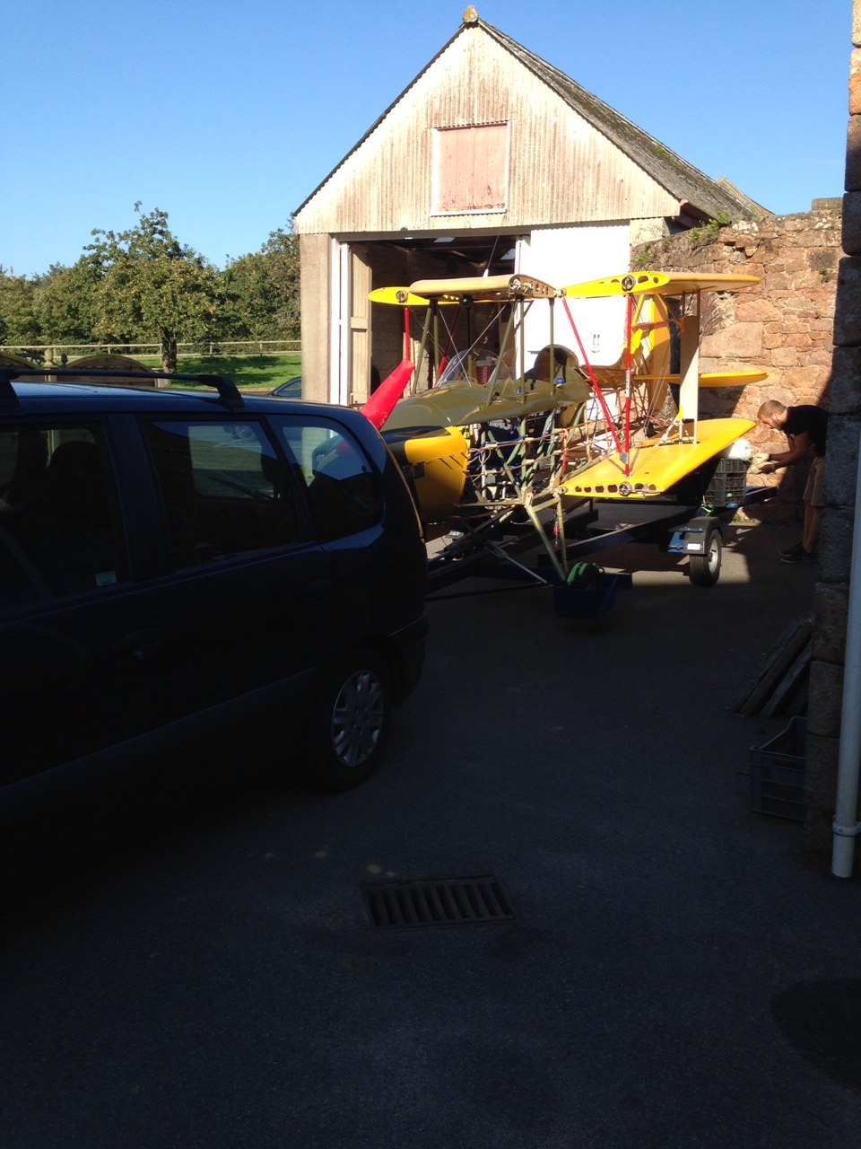
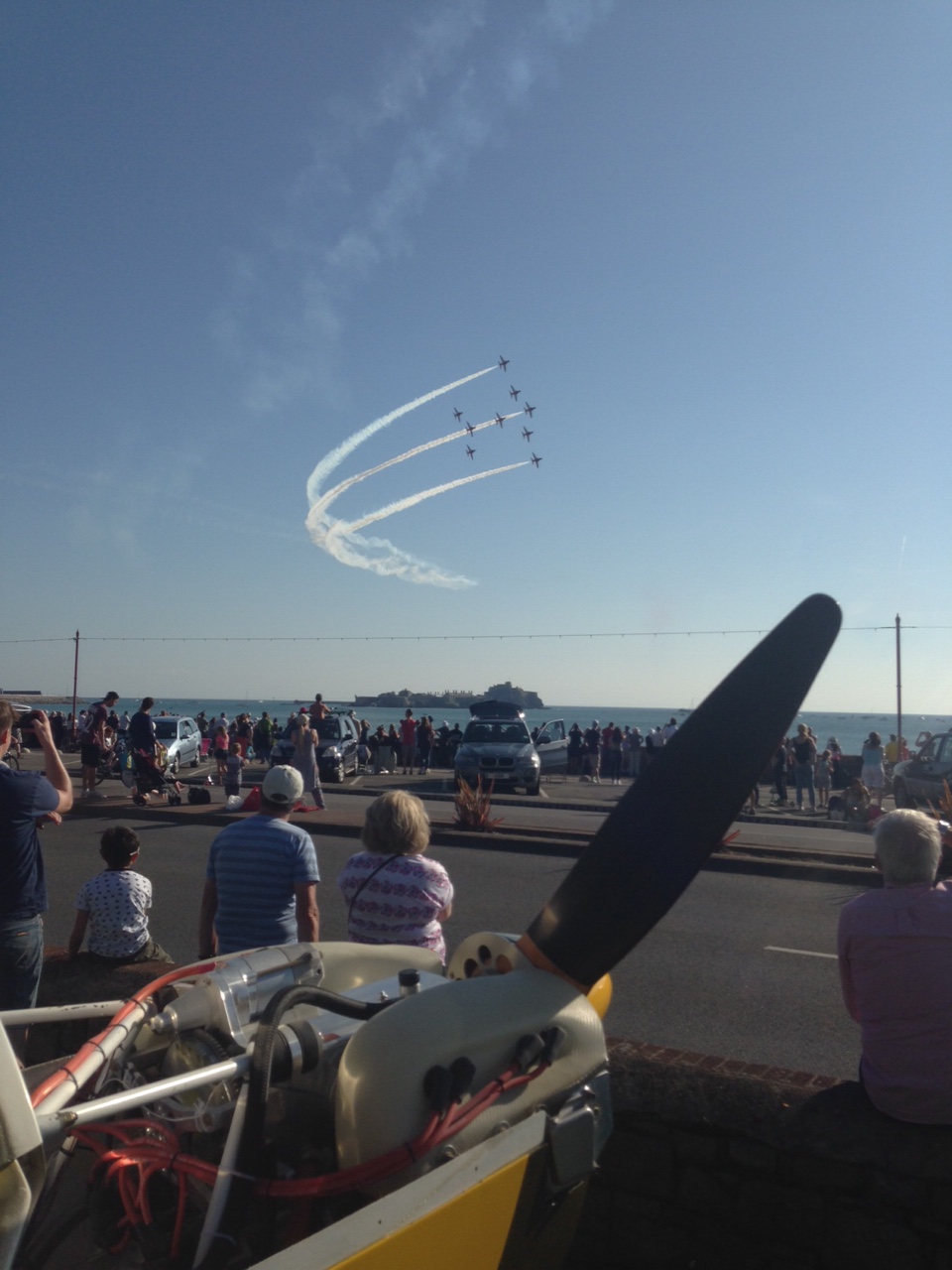
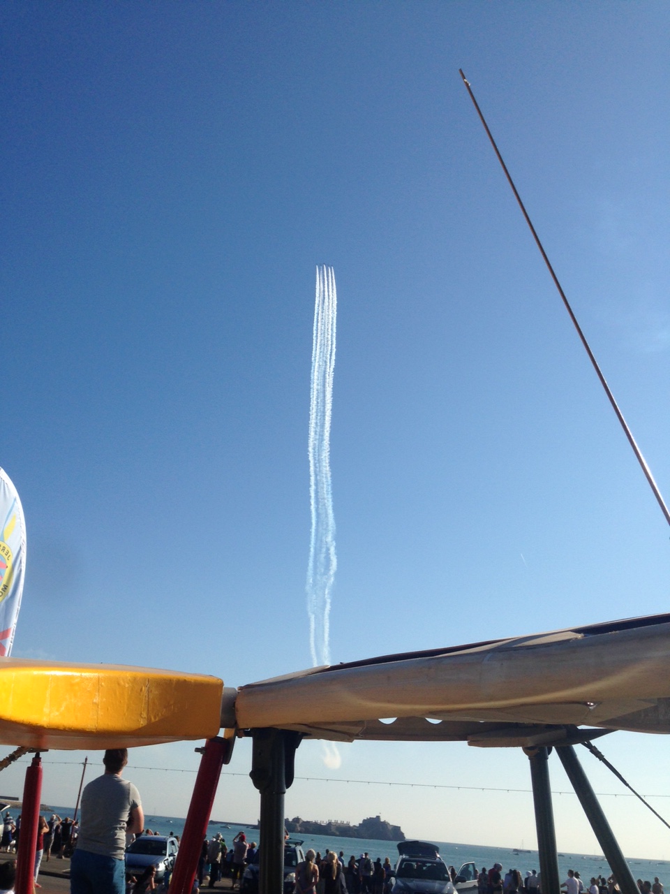
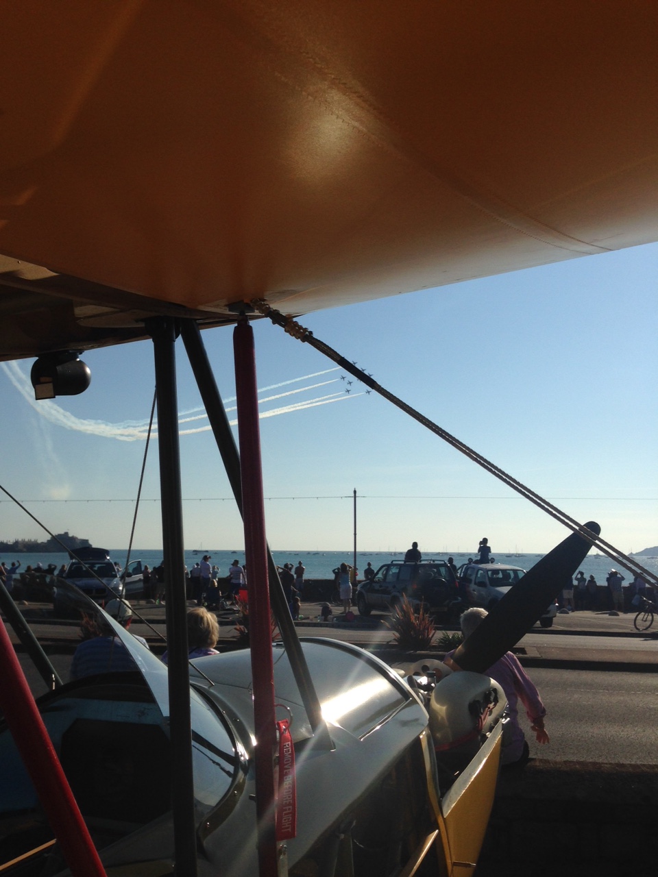
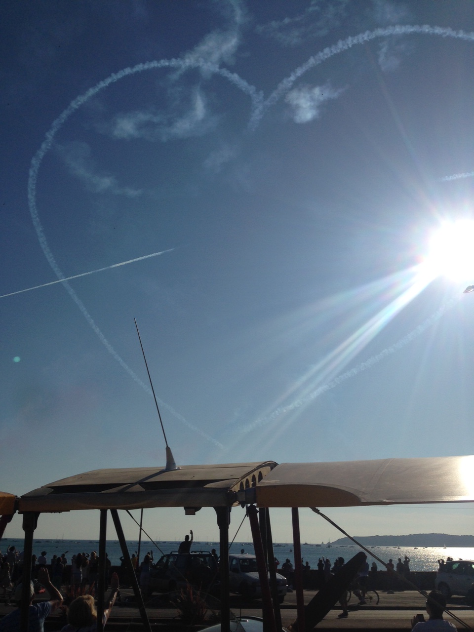
Full on weekend ahead of the Jersey Air Display this week (in the static display – flying next year 🙂

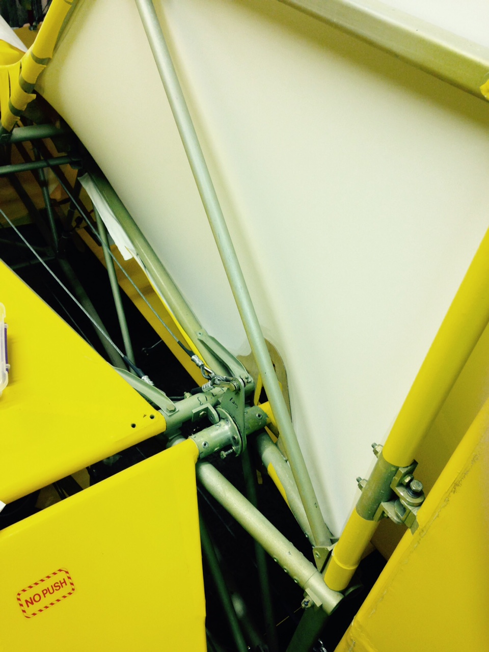
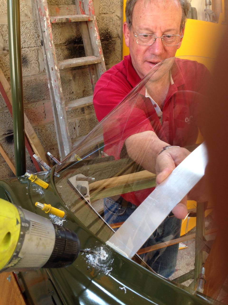
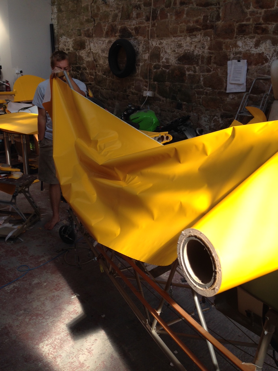
Lots and lots of covering bits including the first AND THE MOST AWKWARD piece … the dreaded bottom of the fin curve to the longerons / turtle deck !

IMG_0956  IMG_0958

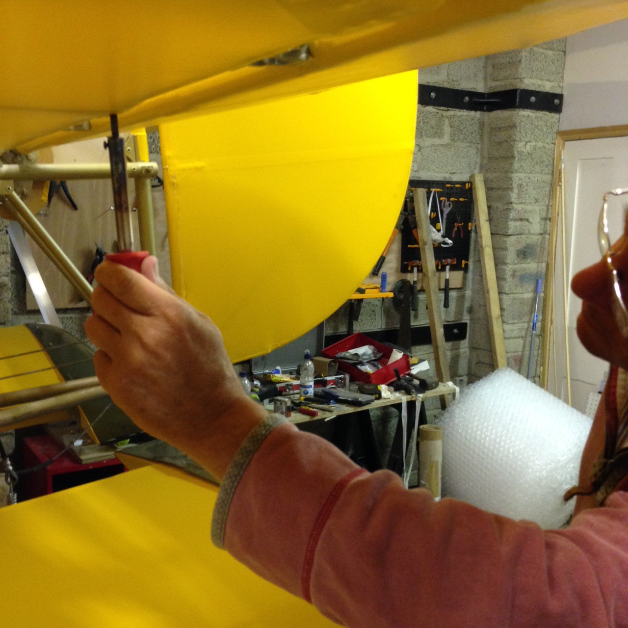
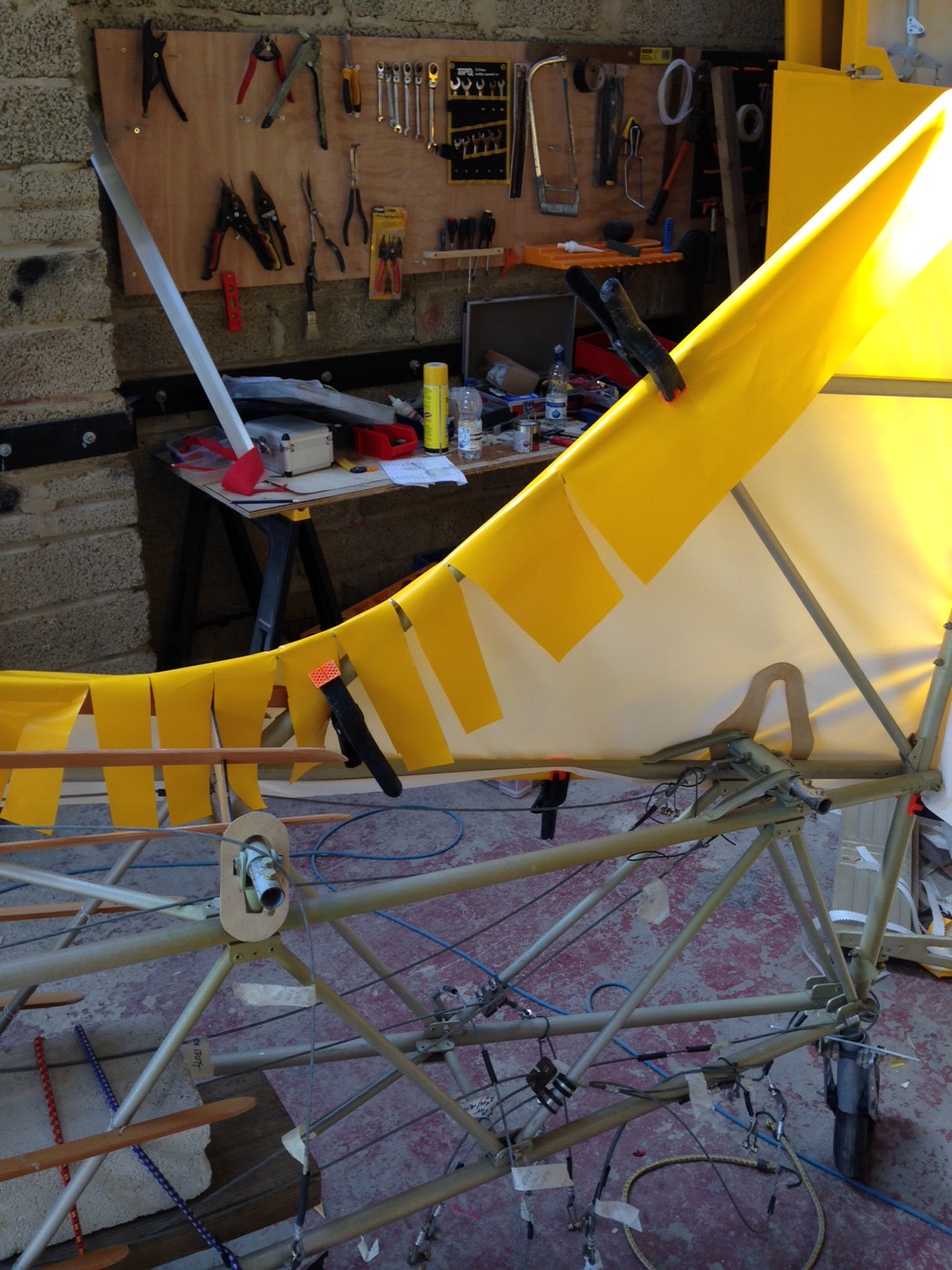
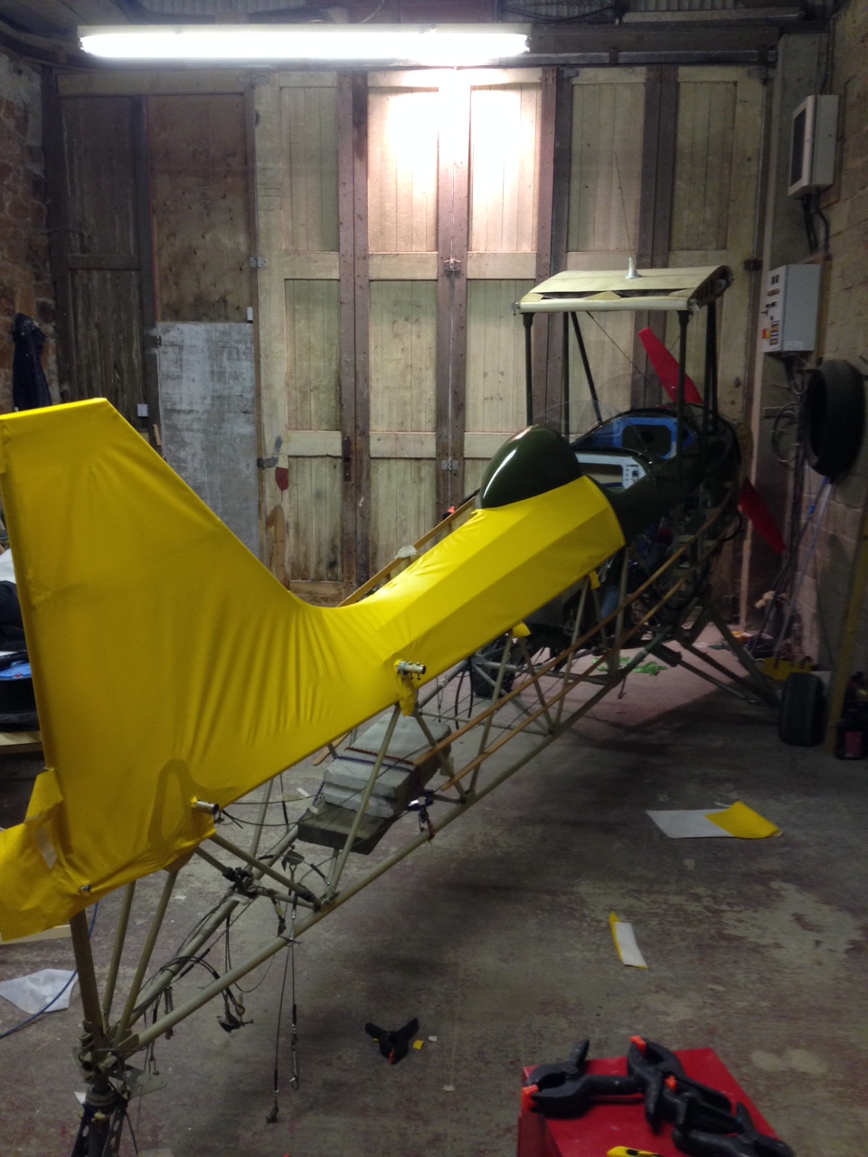
Roll out the material across the top of the tail end and loosely clamp to give some basic form

IMG_0957 IMG_0959

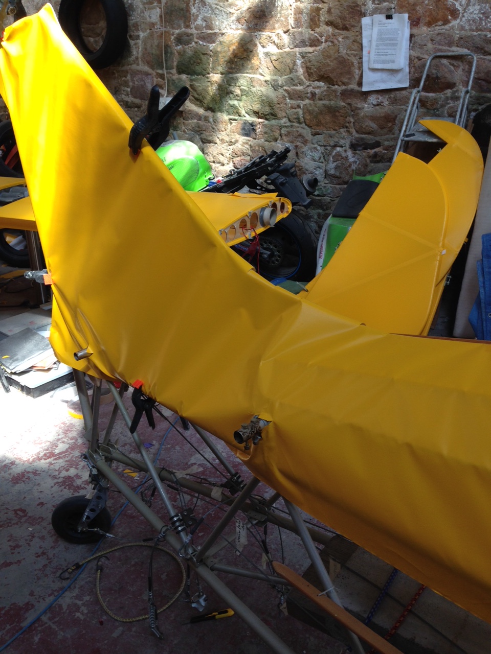
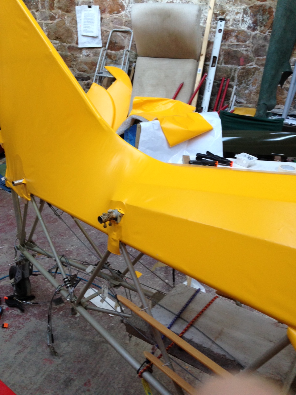
Now start to pull the shape and bring clamps more into play …. I noticed that the tail end of one of the stringers was protruding and making a noticeable point in the material… so took around 20 mm off the end and curved more.

IMG_0965  IMG_0967

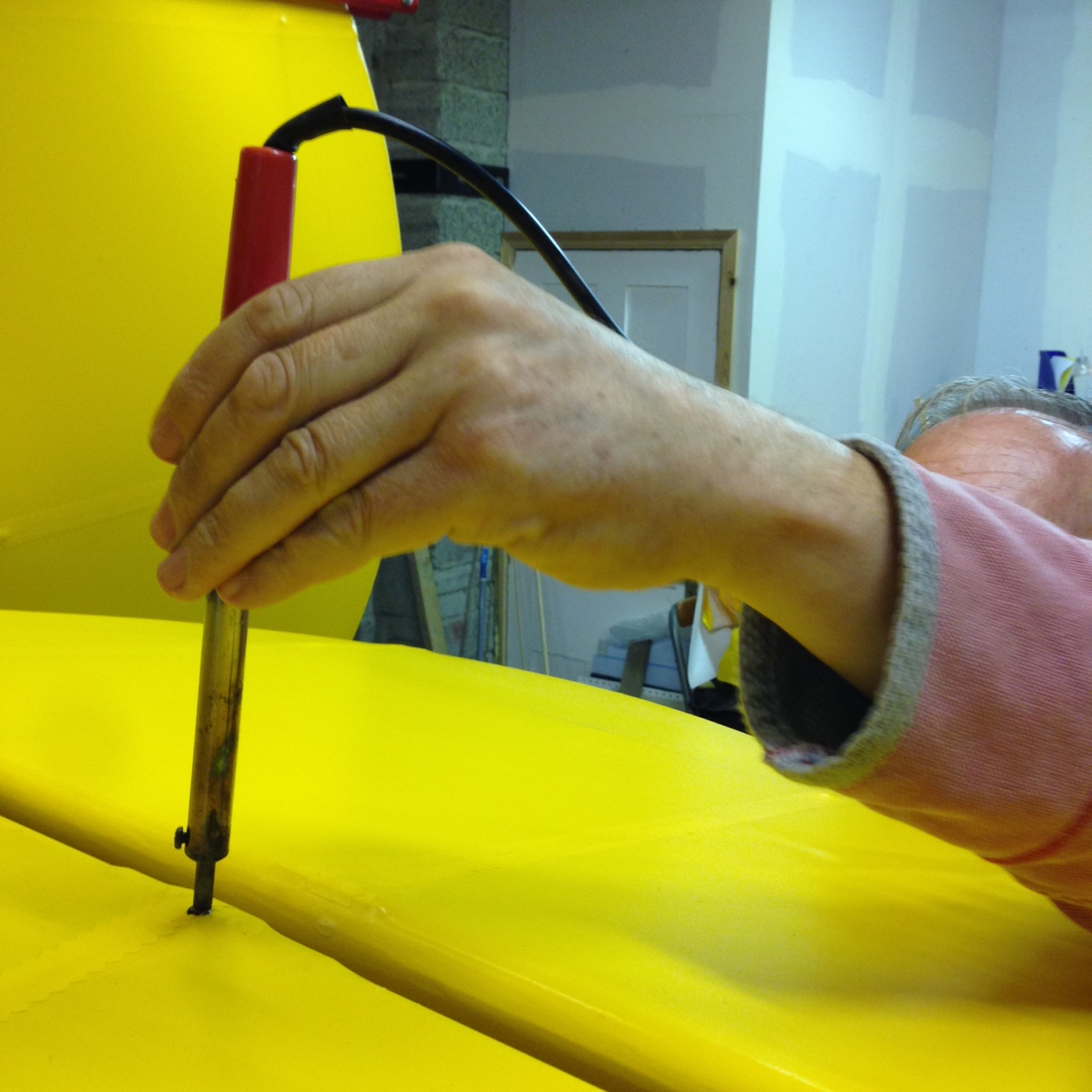
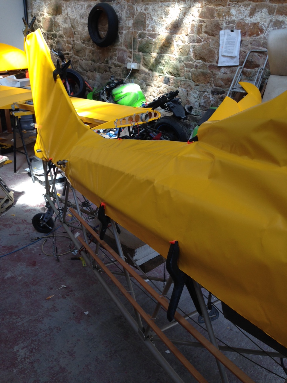
Decided to start ironing from the lower centre forwards and rearwards .. small iron set at 150 (as metal bars) Trying to get as tight as I could on the first pull.

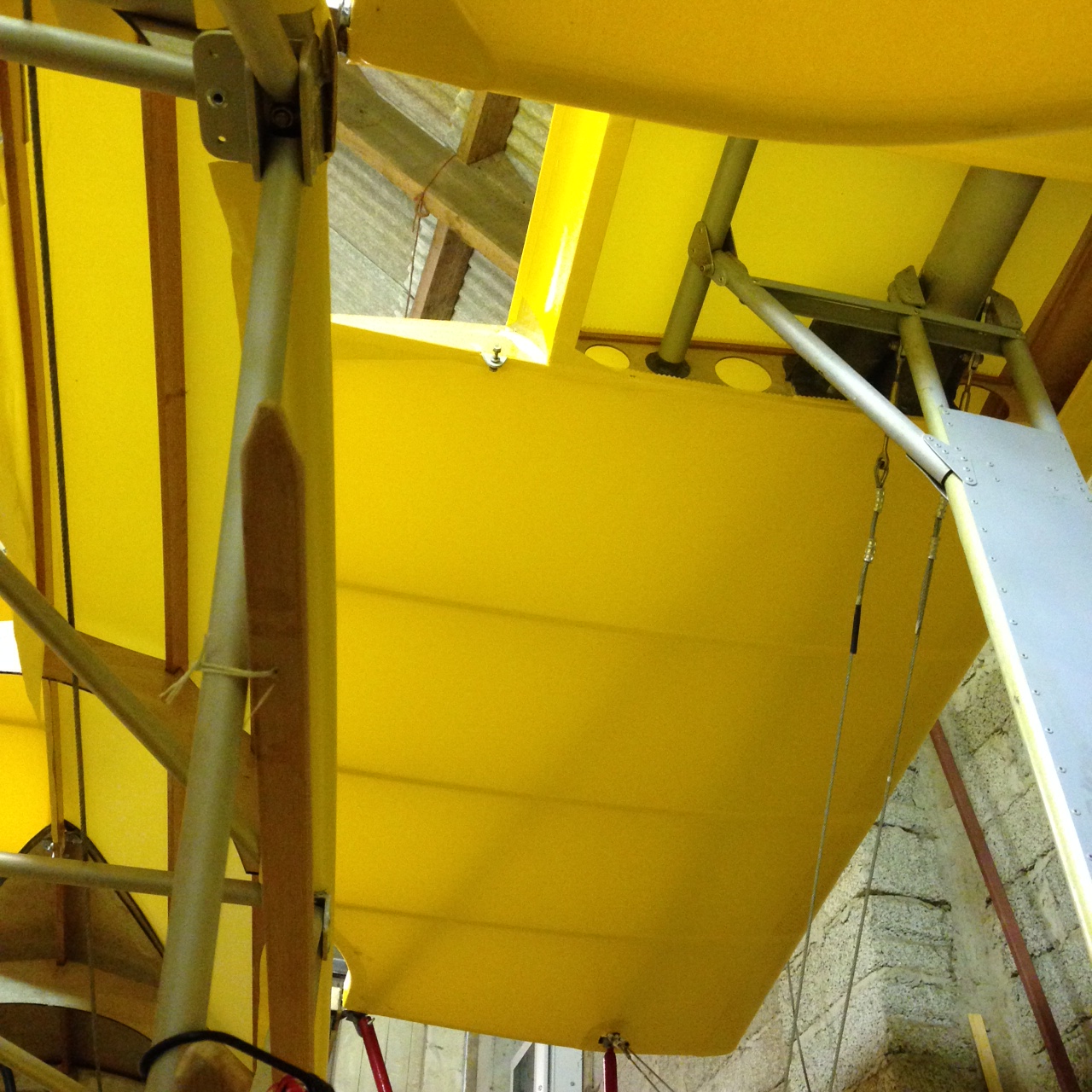
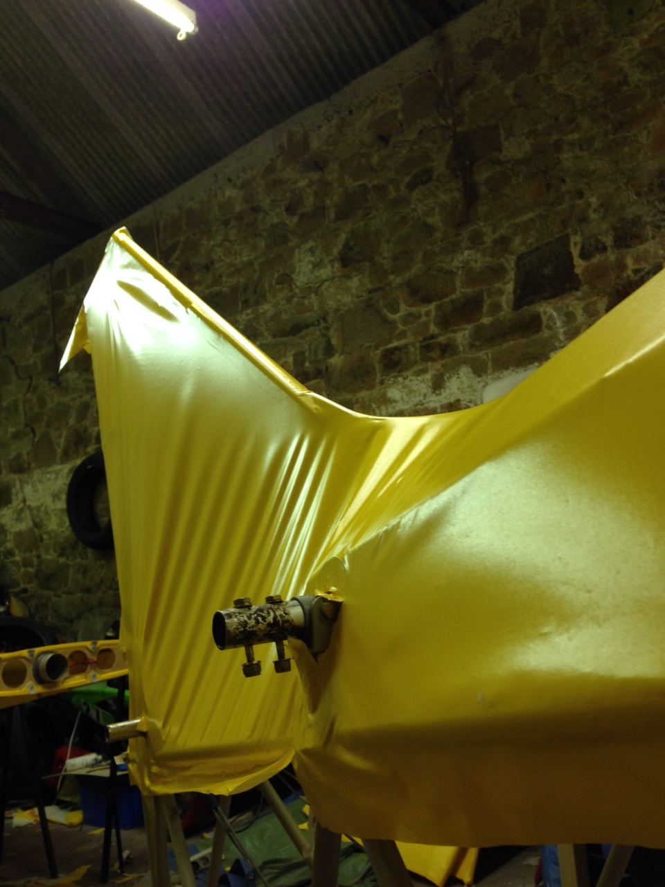
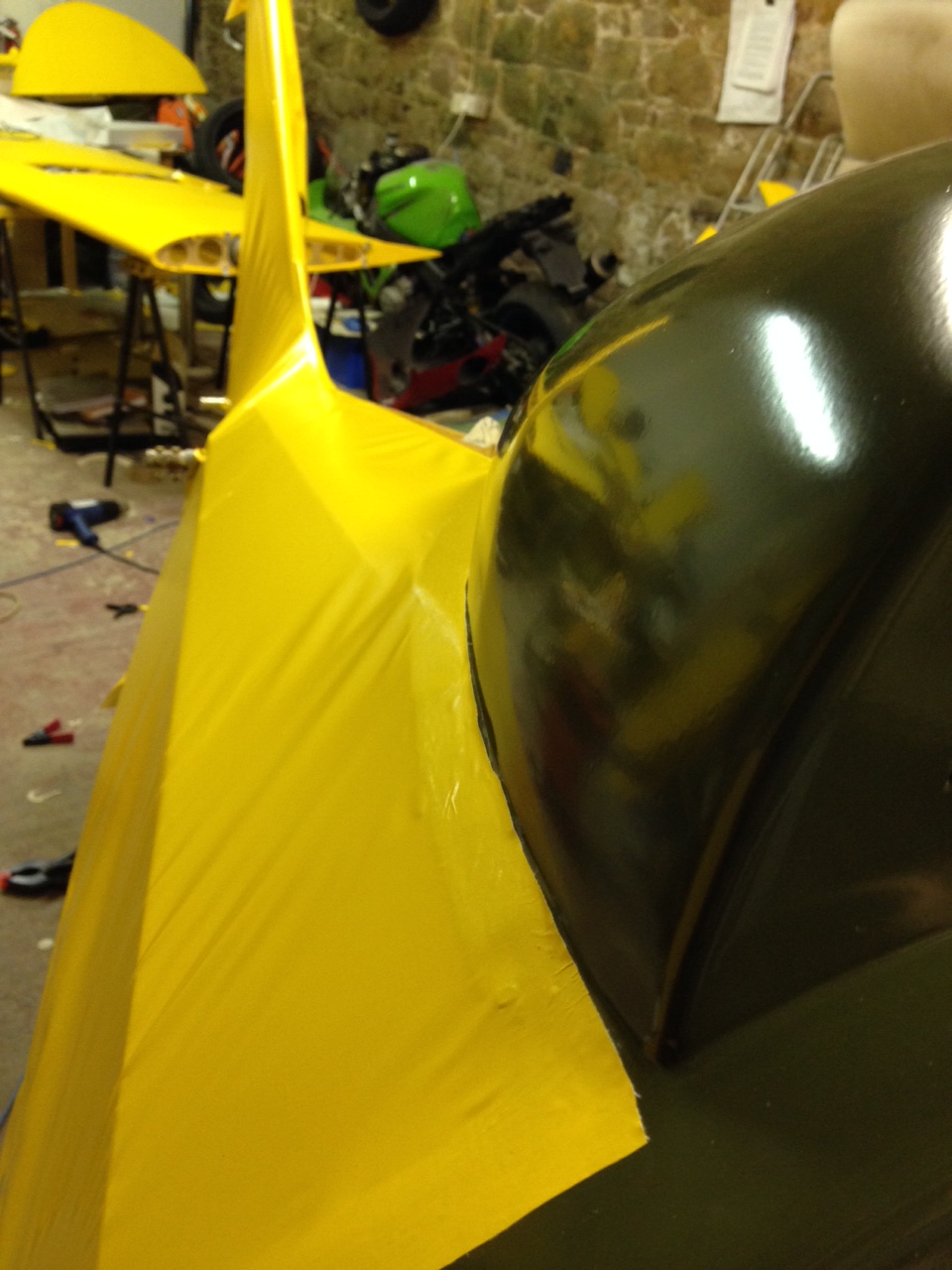
The complex nature of that lovely curve from fin leading edge to the top of the body is frightening to try to get the material to follow. Even just offering up the material is ‘fighting’ to stay straight !

IMG_0961  IMG_0960

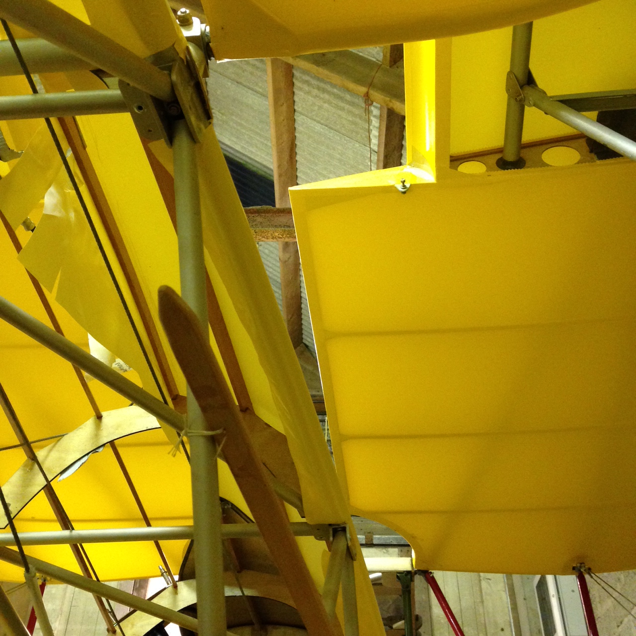
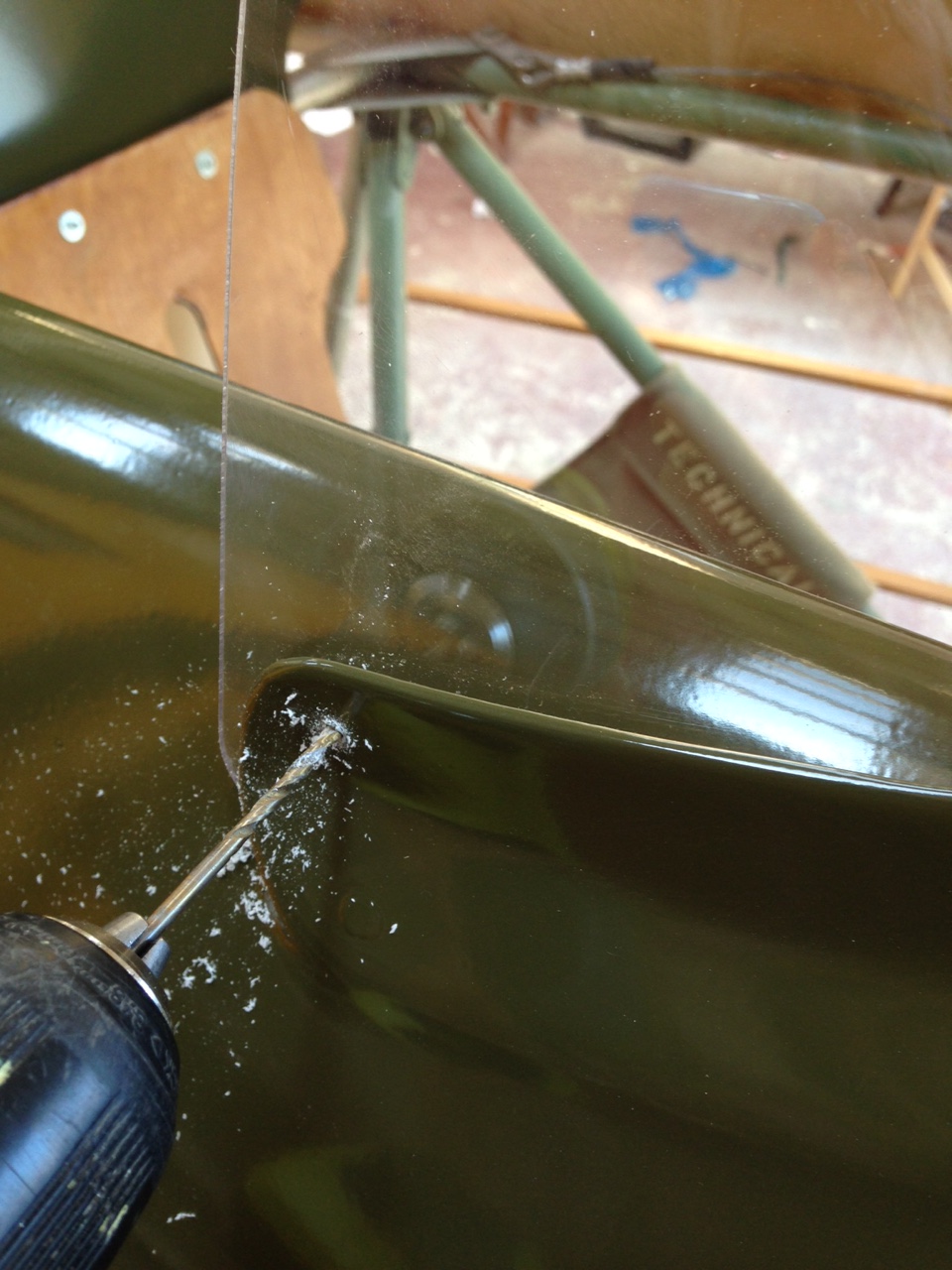
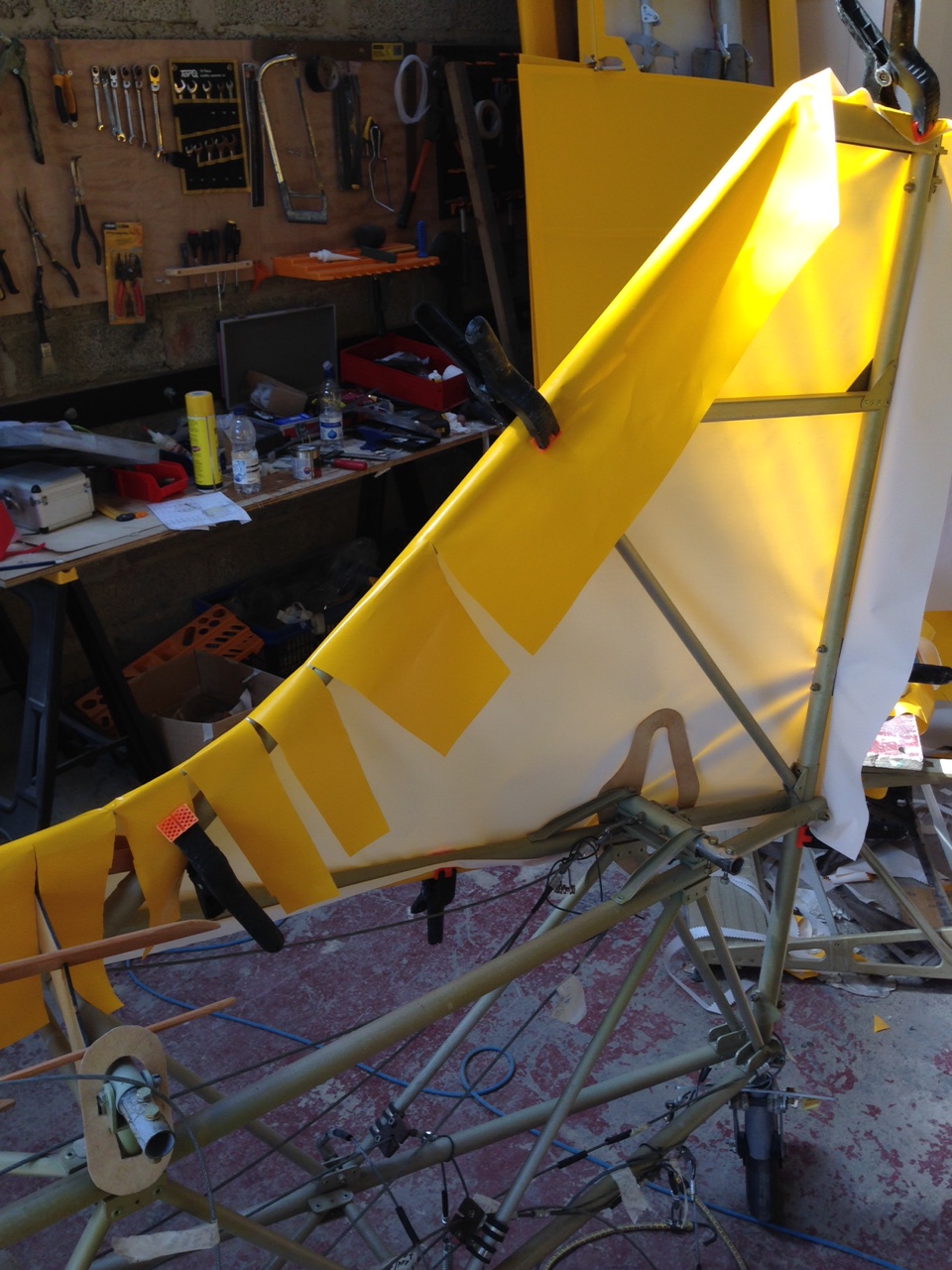
Slit to follow the strake lines BUT make sure the hotmelt glue is on all the parts that you might wish to secure it to ! Once the se cuts go in the whole thing starts to ‘behave’ and follow the lines .. but don’t cut too much as it will affect the relatively narrow surface area it grips to.

IMG_0968  IMG_0969

I have learned that having an initial run through with the heat gun around 130 starts to take up the slack gradually .. rather than just blasting through on 150+. Also, my very good friend and fellow builder Danny (Baker) kindly advised me on cut patterns for the body and care on this curve .. too much rapid shrinkage could distort the underlying framework

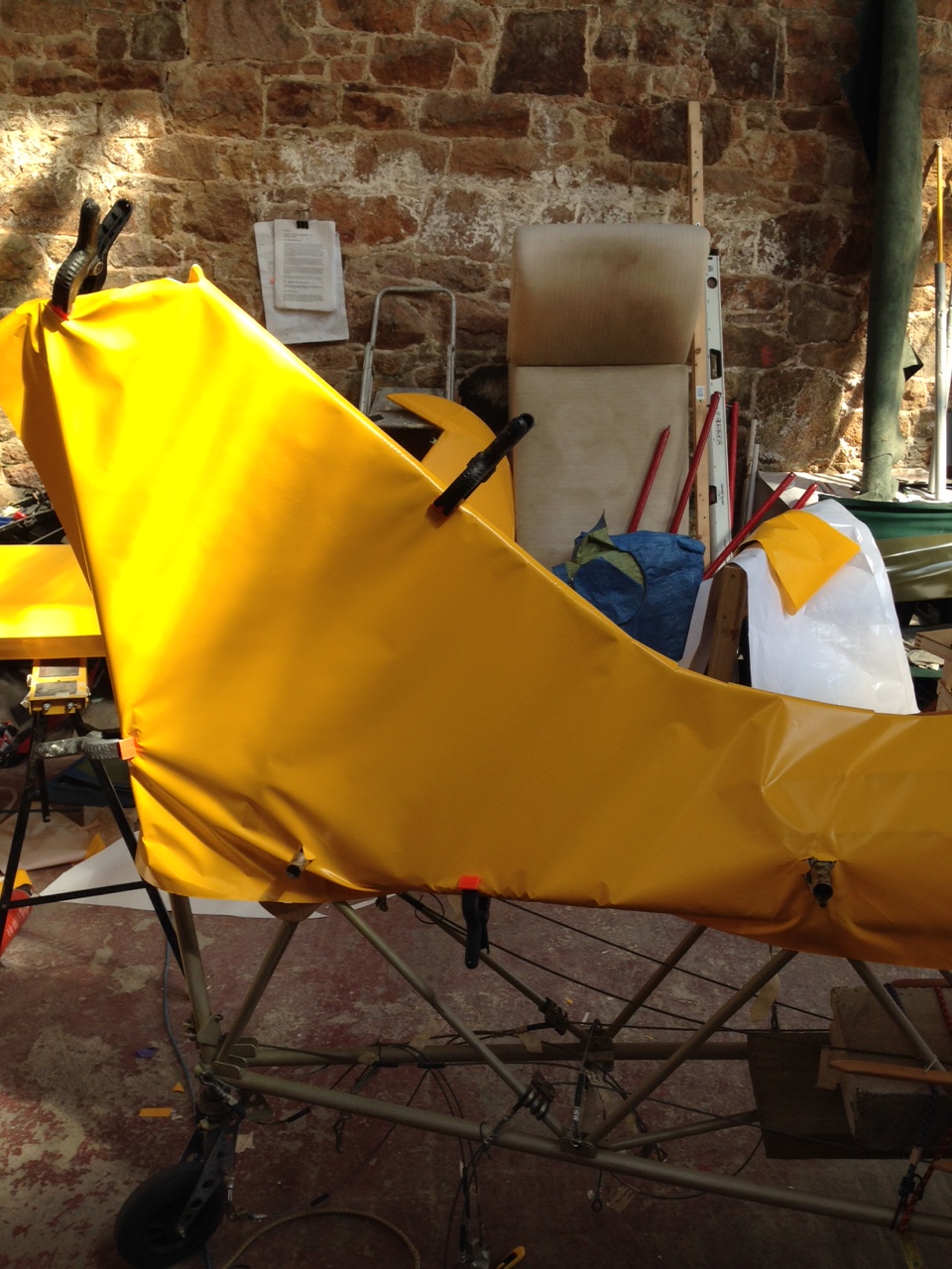
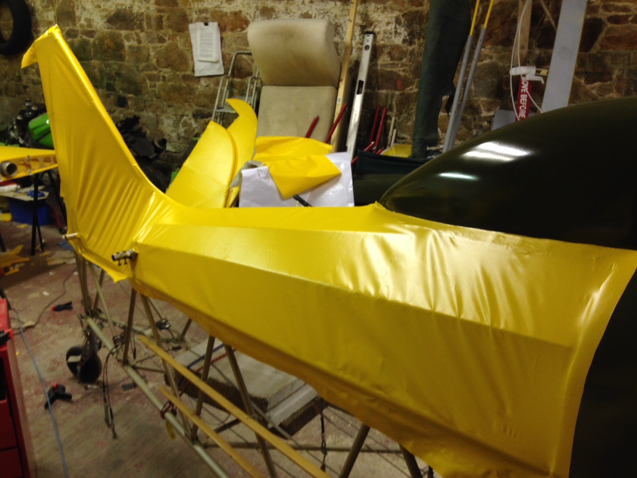
The bit securing to the fibreglass decking was easier than I thought .. again complex curves and adverse cambers but it looks neat once done.

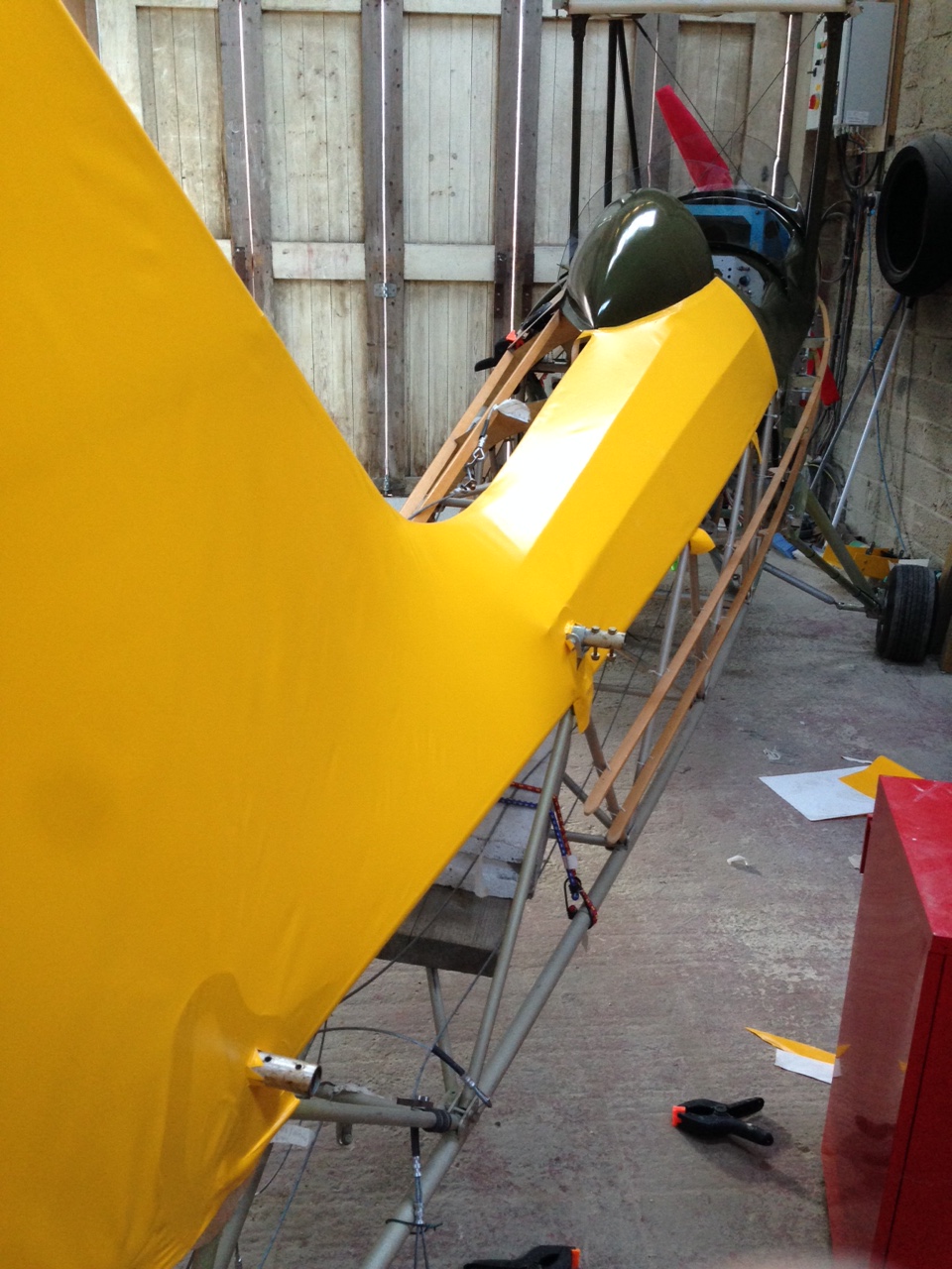
Returning to a previous awkward ripple once cooled a bit brings much more control to the phased tightening and even look ensues !

IMG_0971  IMG_0970

Second run through and have had to crank up from 130 to 150 to encourage that latter (now small) ripples to flatten out in a curved way !

Very pleased (and HUGELY relieved) at the result !

The ‘other’ side should be somewhat easier as its simply overlapping .. already templates based on this first side (reverse image !)

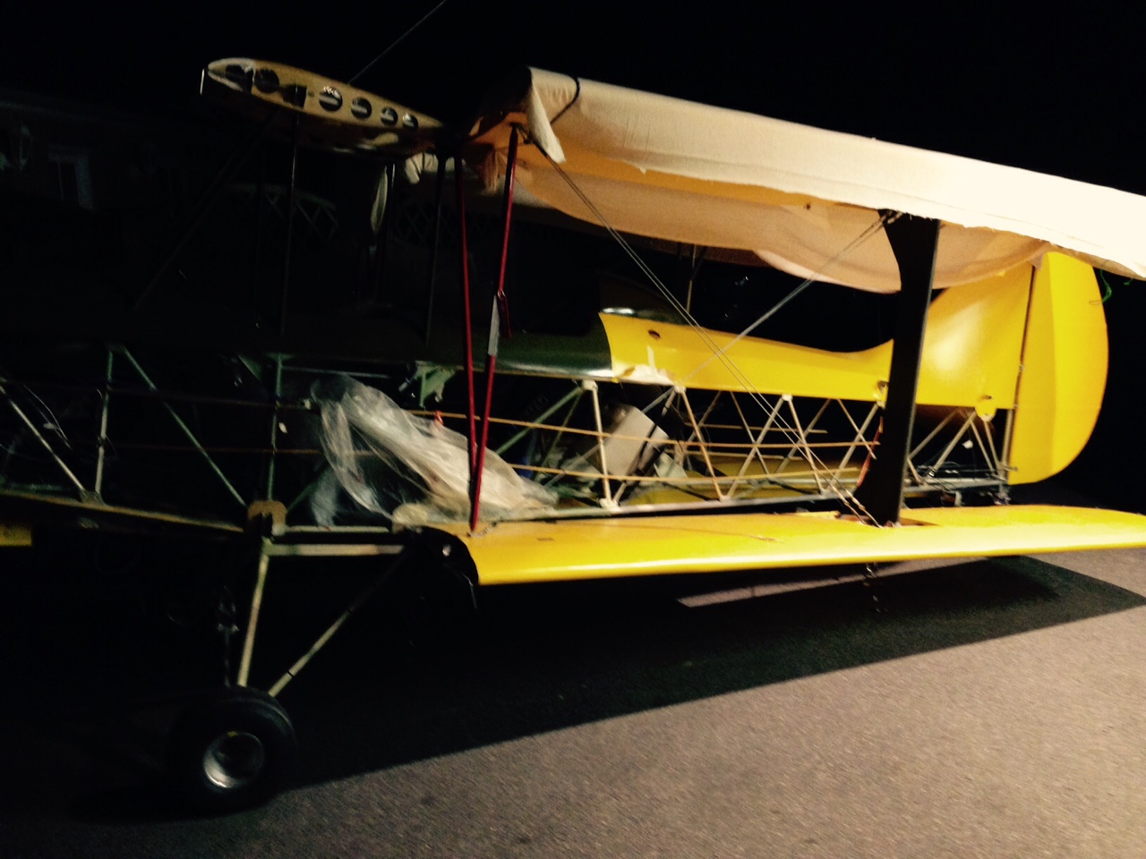
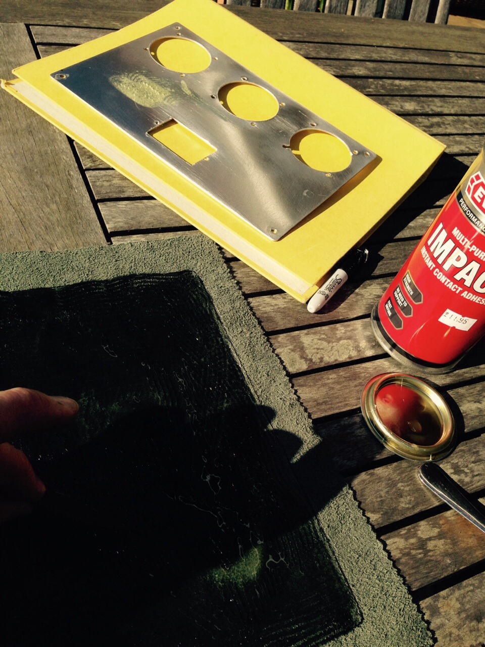
Aim was to cover one piece in Cub Yellow on top deck and then paint it green .. but I kinda like the two-tone look at the moment !

Invasion Marking go on wing 3 !

Wing 3 just about complete … just adding the taped off glued area for the re enforcing strips then its just Leading and Trailing edge.

IMG_0866

Wing 4 – Port lower … has had the final smoothing of the wing step completed and pre glued. Also underside material in place and glue drying for next session.

Weekend away (arggggh) in UK but back to finishing last wing Tuesday/Wednesday


Blog at WordPress.com.

Up ↑