Ariel location and fixing – Part Deux

Mike, who has seemingly endless brilliant contacts called me the other day, having seen the ariel location post …. call me now .. was the message ….

Duly called and arranegd to meet Mike and mystery guest at the barn at lunchtime …

Mystery guest turned out to be a very nice chap called Chris who is the wiz at Jersey Airport for all things electronic … well, what he didnt know about groundplanes was definately not worth knowing ….

Both Mike and I had a 45 minute lesson, overview, revelation on what groundplanes are, how they work, how they work better ! and whats more Chris delivered in easy to digest language …

So – Plan 2 –

Scrap the metal bar across the cabin – so two small rivets will be drilled out and then the bar removed. It WILL work and probably absolutely fine around the circuit … but as pretty much every single flight I do involves filling tanks, filing a couple of flight plans and submitting gendecs to whichever police force decide they need them as well as the local authorities … anyway .. suffice to say I need a radio that will still work around 50N as I cross the Channel ….

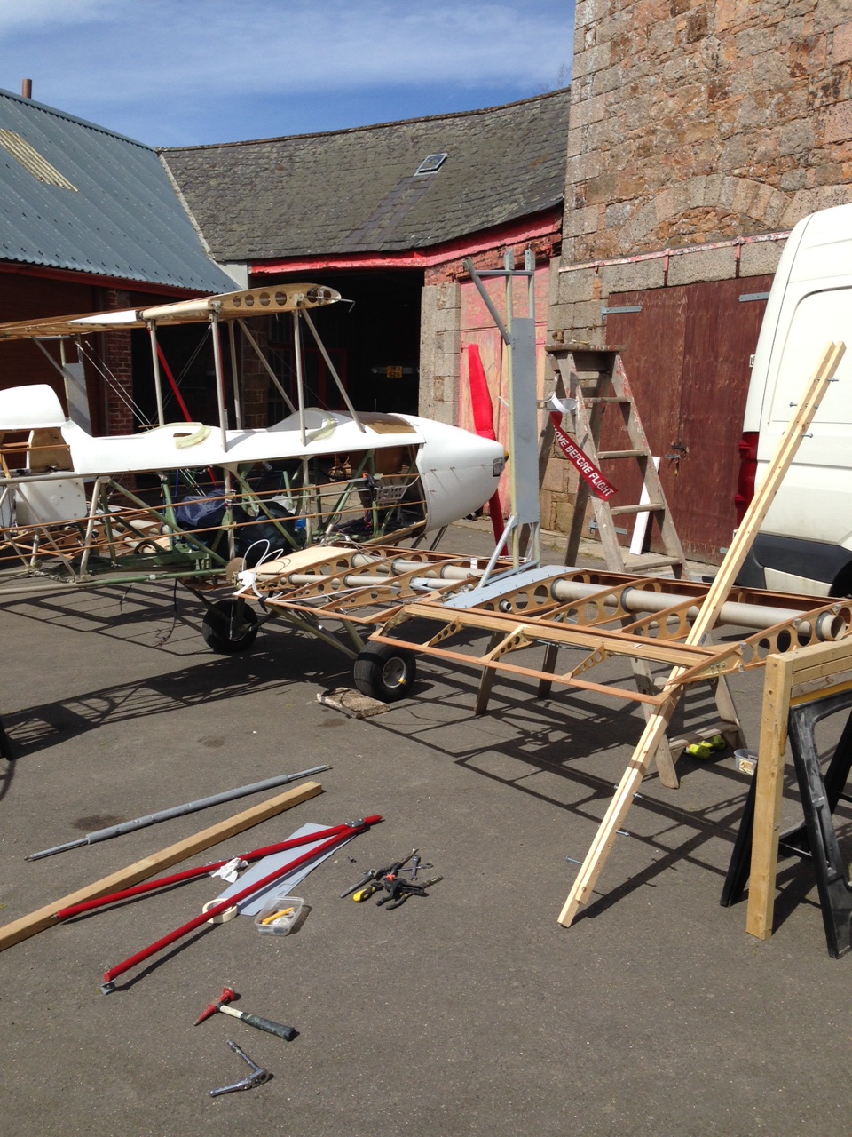
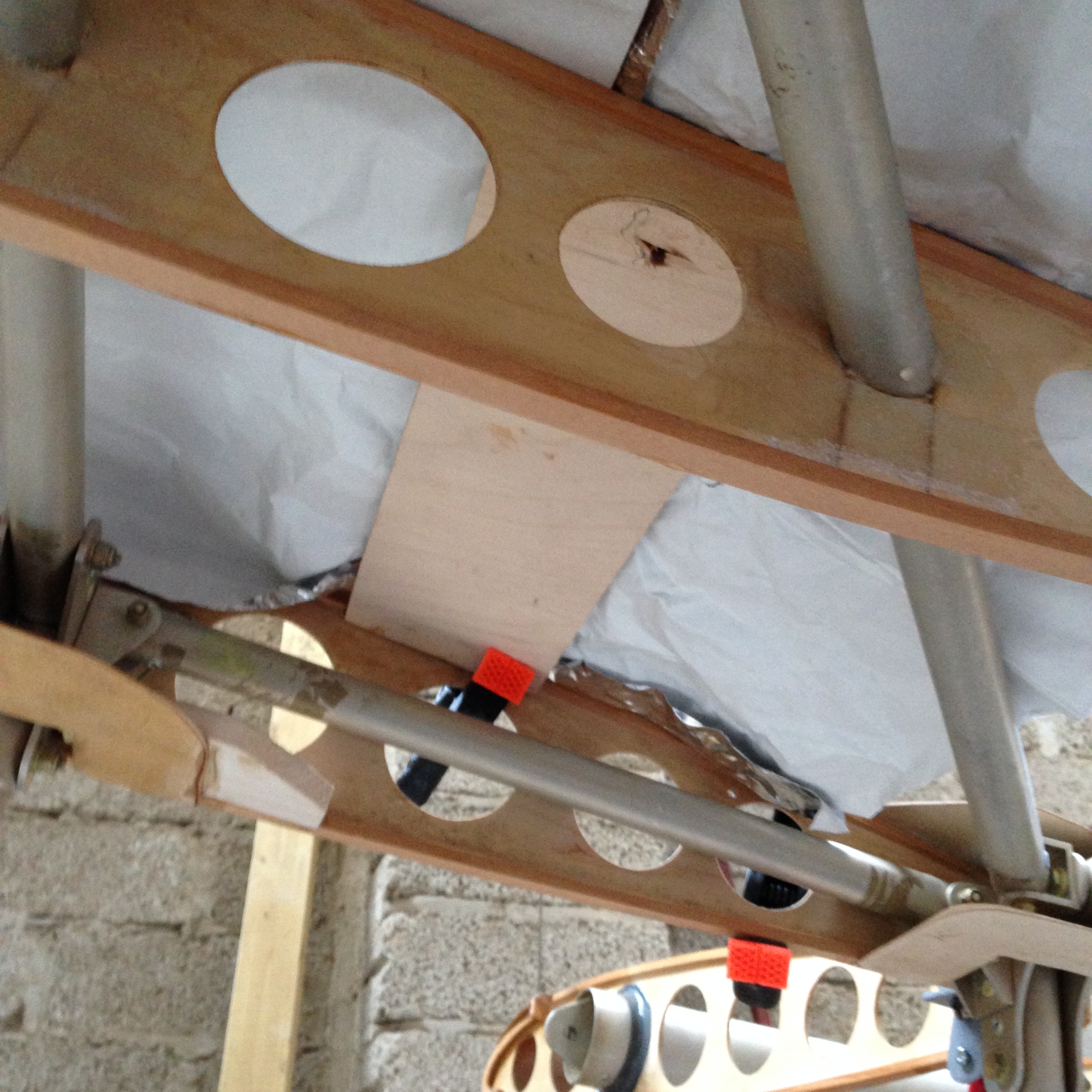
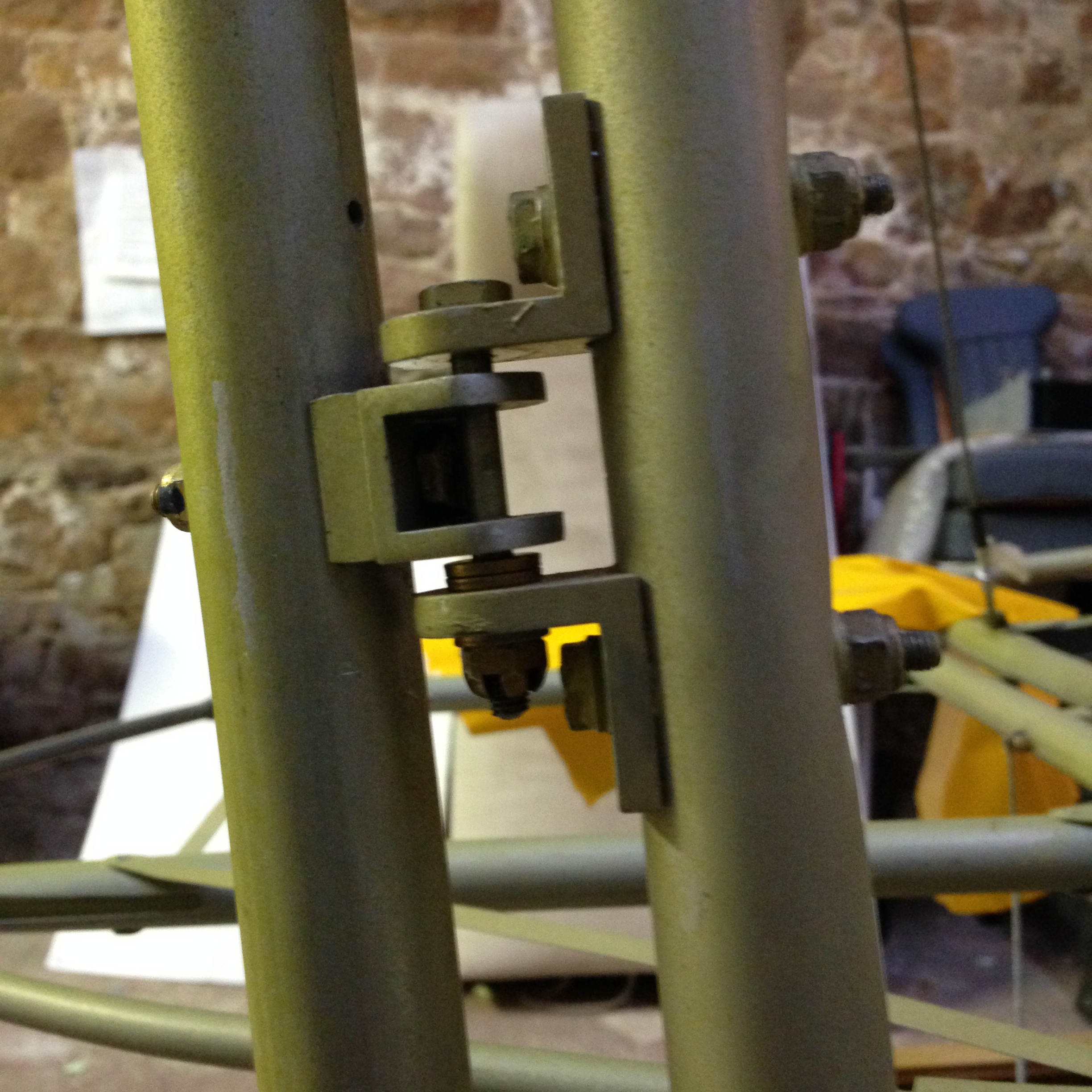
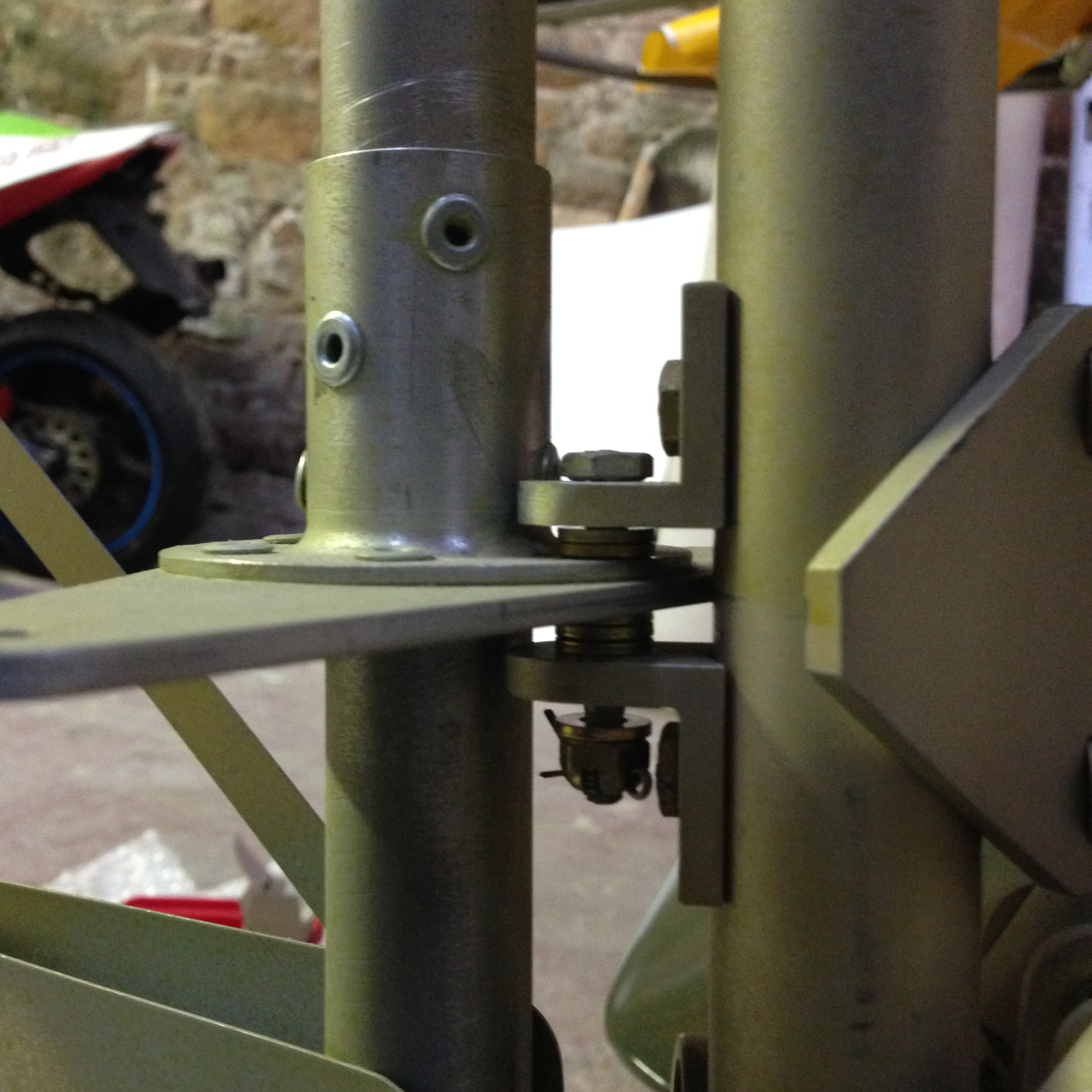
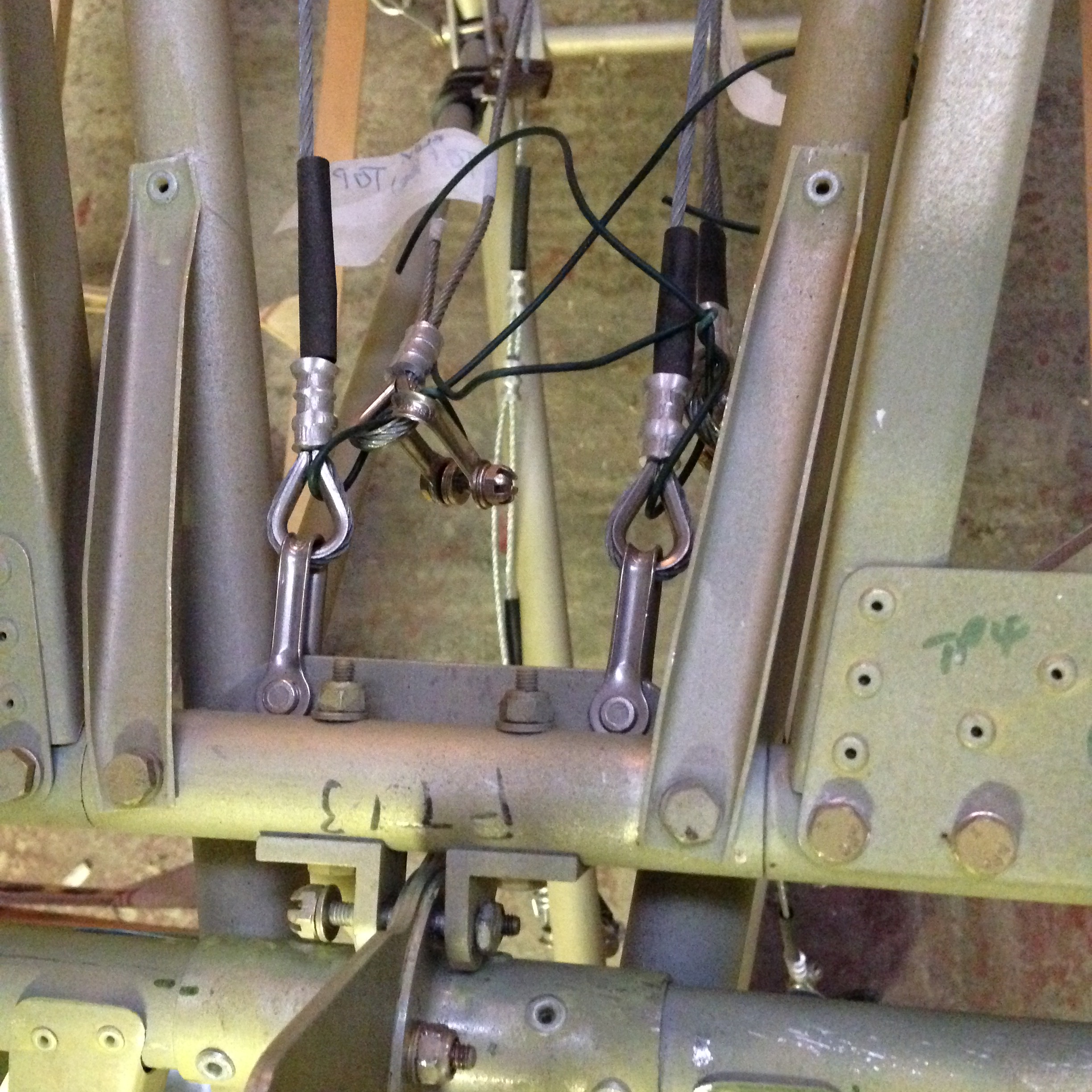
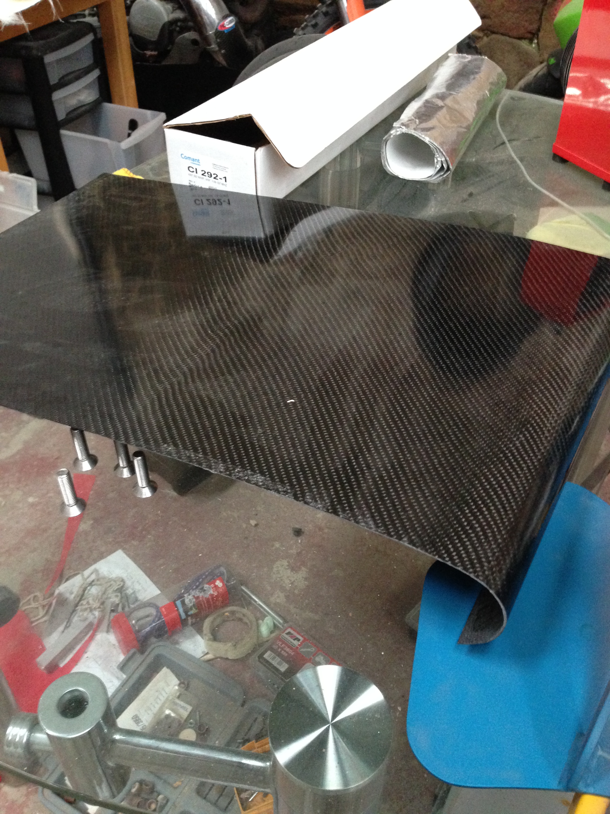
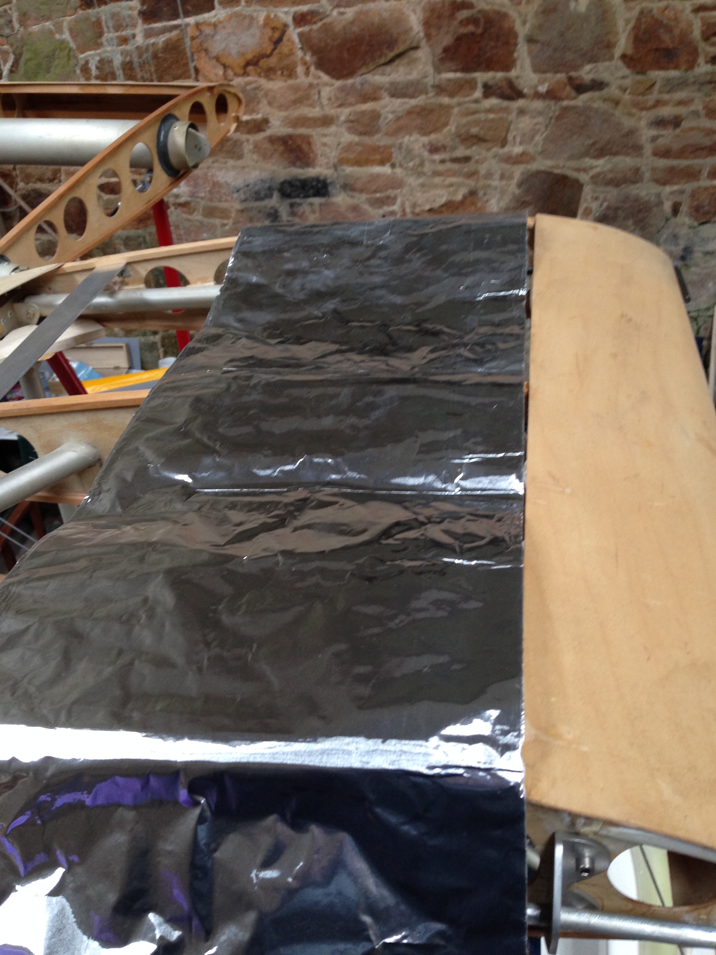
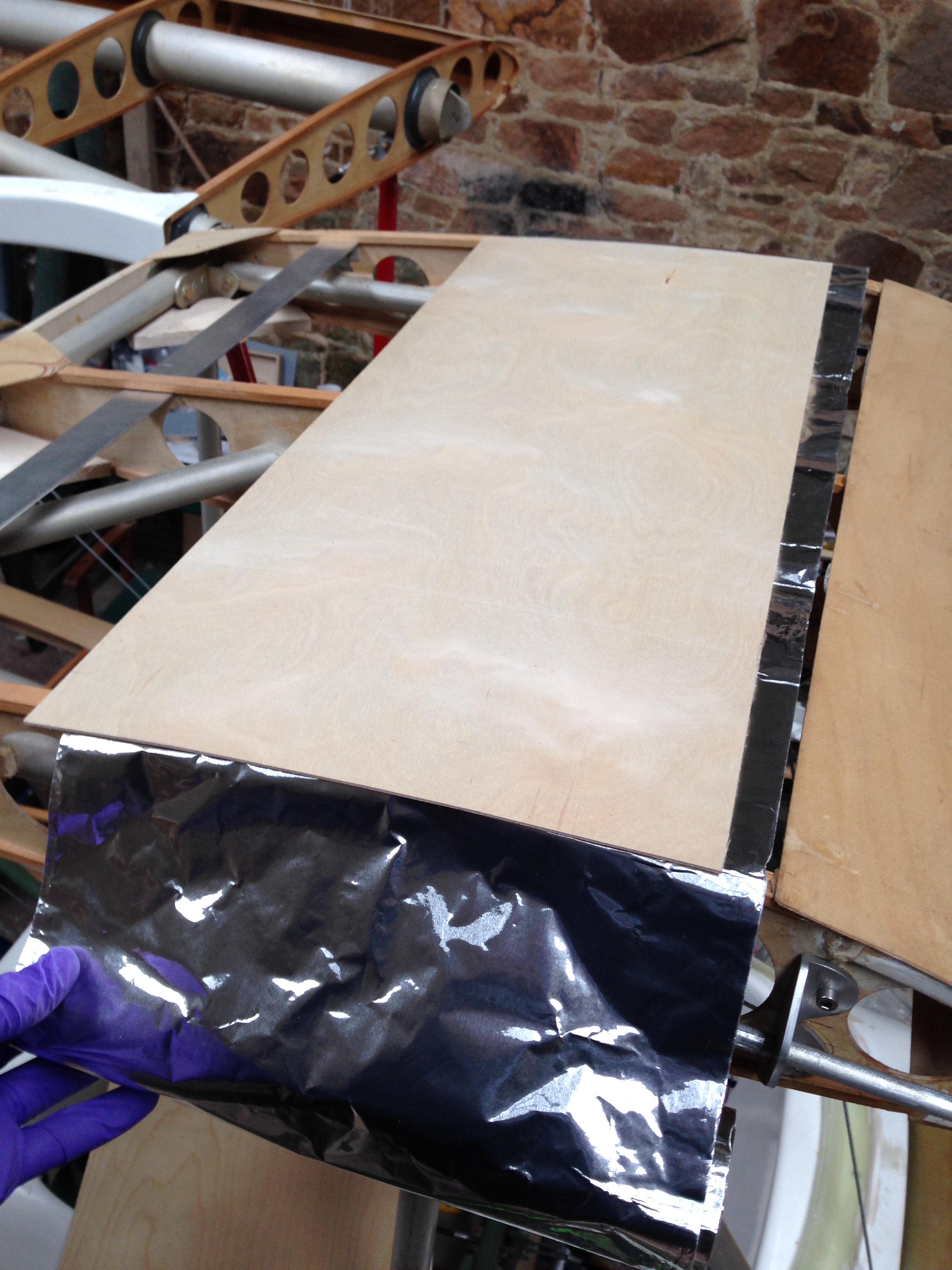
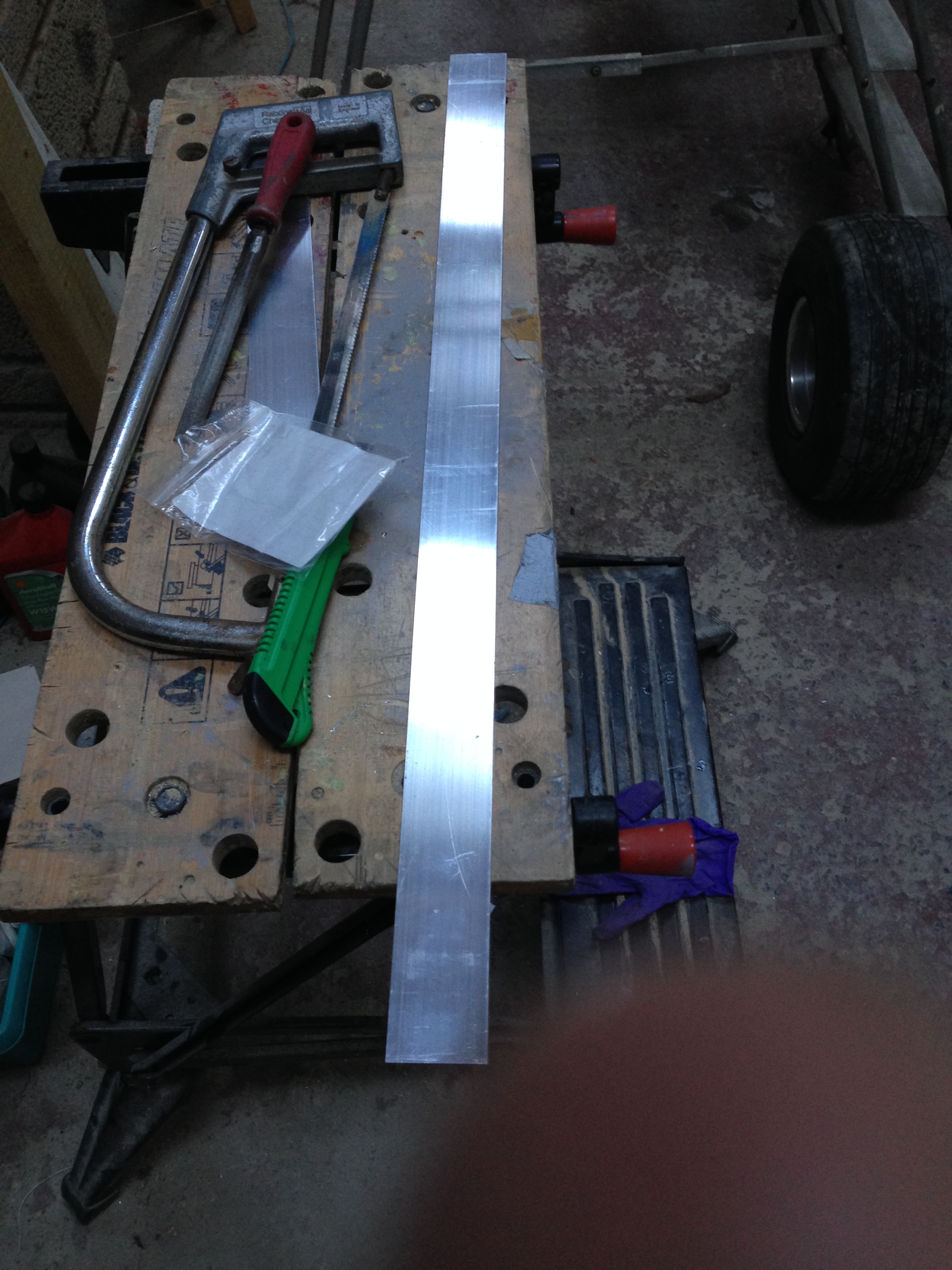
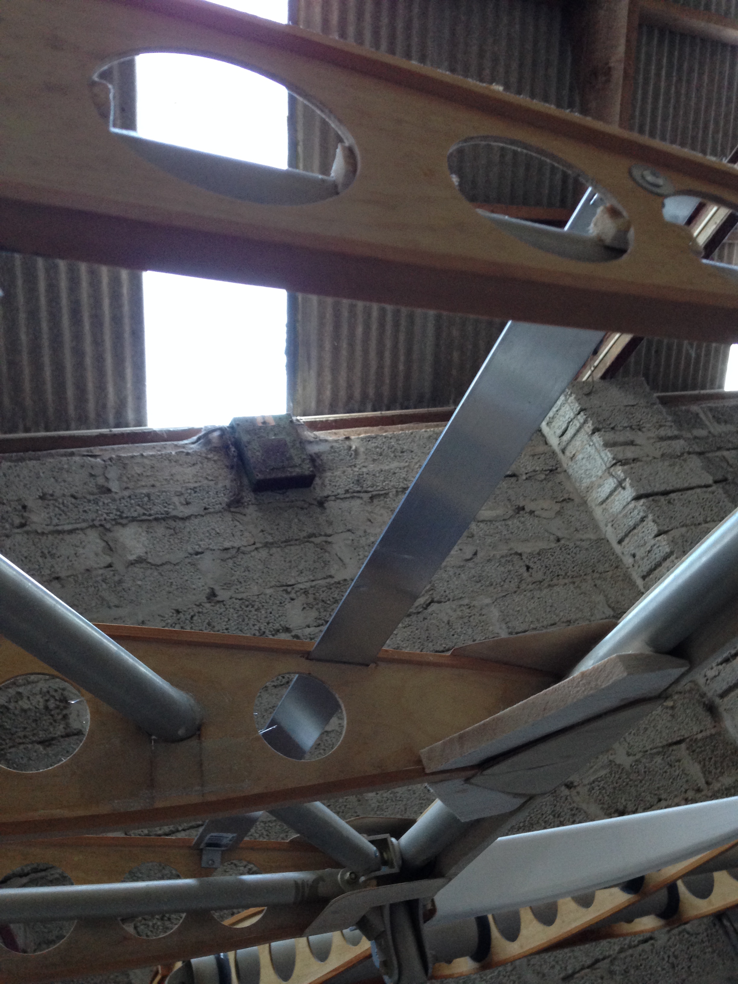
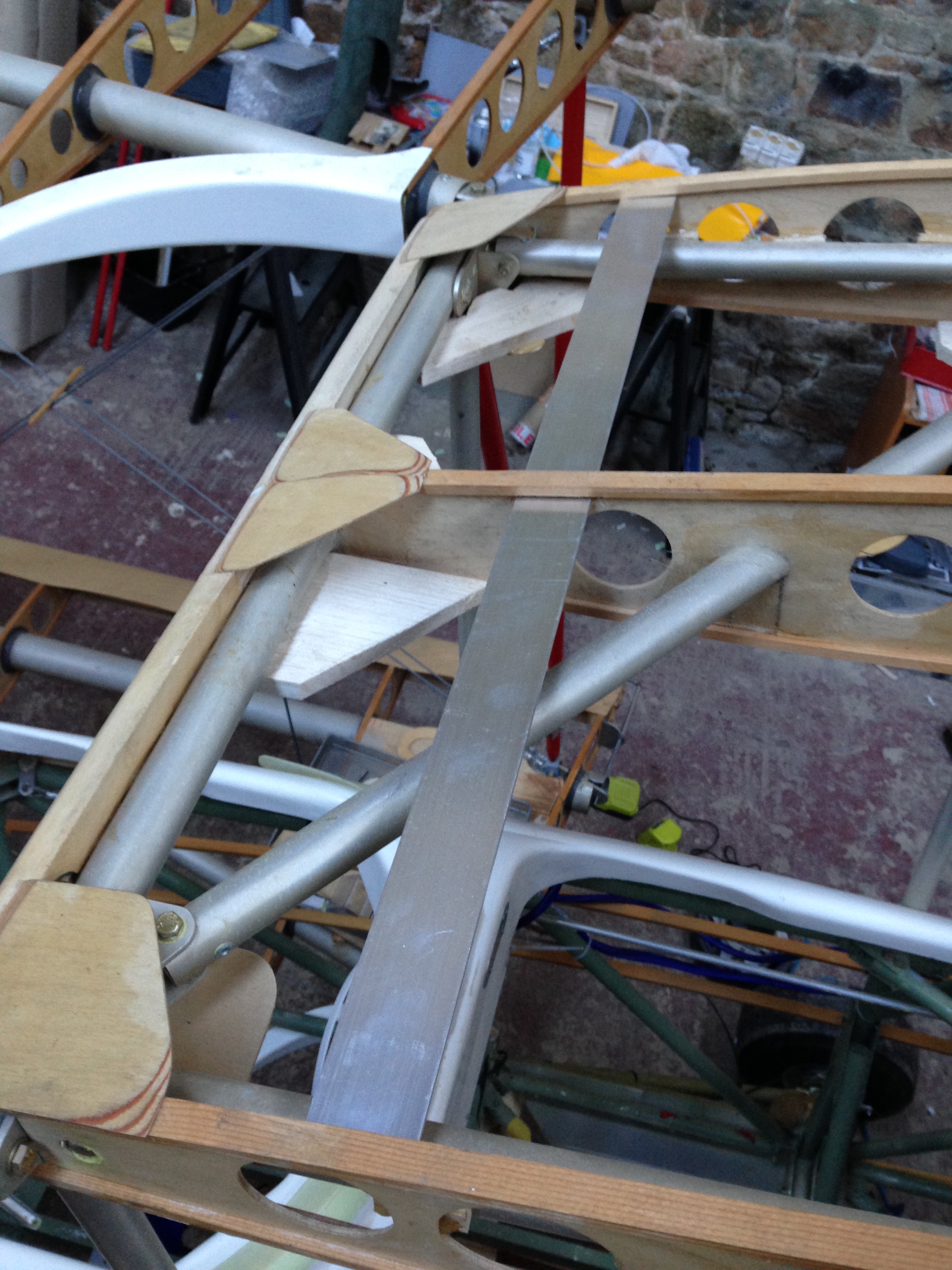
The new plan is to use the aluminium sheet base plate roll that Chris very kindly provided and cover the entire top of the cabane with it to provide a continuous sheet that effectively maps a circle (the radius of which matches or exceeds the length of the steel whip Ariel.
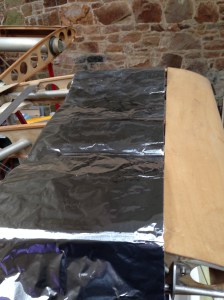
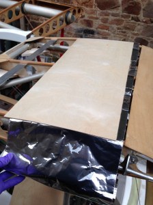
IMG_0147  IMG_0148

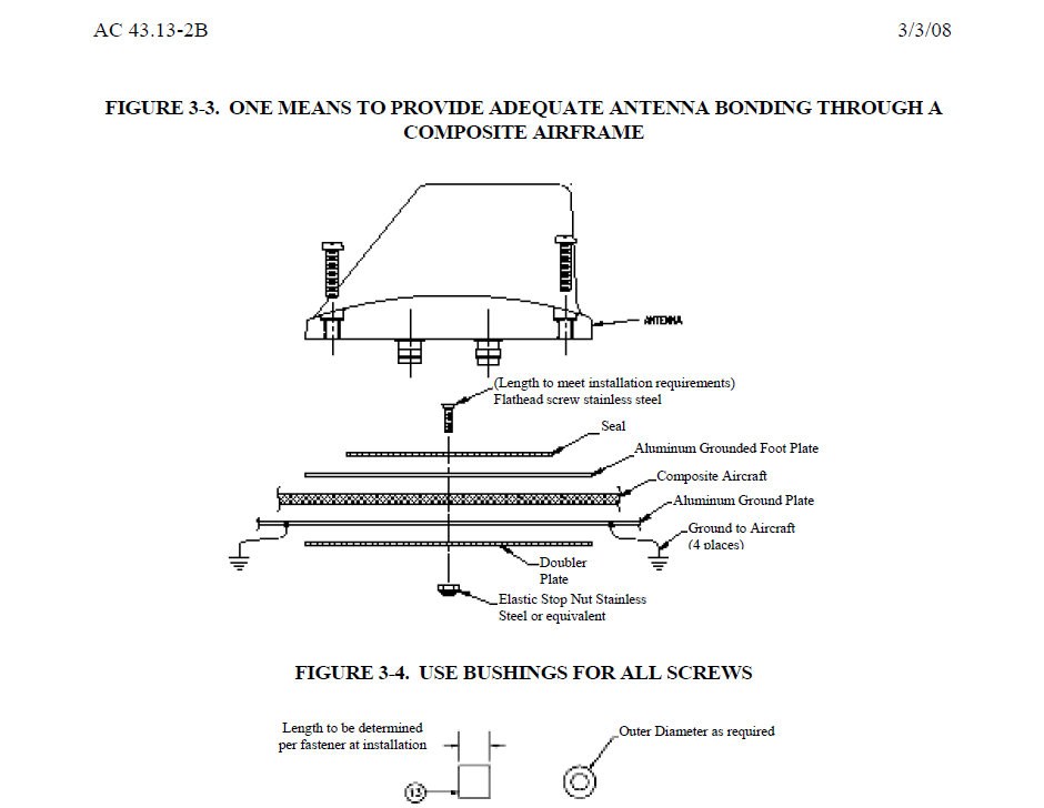
Chris also provided a link to a PDF that has a whole chapter dedicated to JUST this topic. So the aim will be to lay the alloy sheet and then top it (to create a sandwich and smooth surface for covering) with 1.5mm sheet ply.
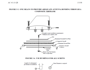
Ariel fit

Did you know you can calculate the load on an Ariel by using the formula below !

D=0.000327 AV2

(The formula includes a 90 percent reduction factor for the streamline shape of the antenna.)
D is the drag load on the antenna in lbs.
A is the frontal area of the antenna in sq. ft.
V is the VNE of the aircraft in mph.
Example: Antenna manufacturer specification frontal area = 0.135 sq. ft. and VNE of aircraft is 250 mph.
D=0.000327 x .135 x (250)2
=0.000327 x .135 x 62,500
= 2.75 lbs

OK – If the Sherwood is doing 250 mph – the reception of the antenna is pretty academic as I would have already lost all 4 wings !!! 🙂

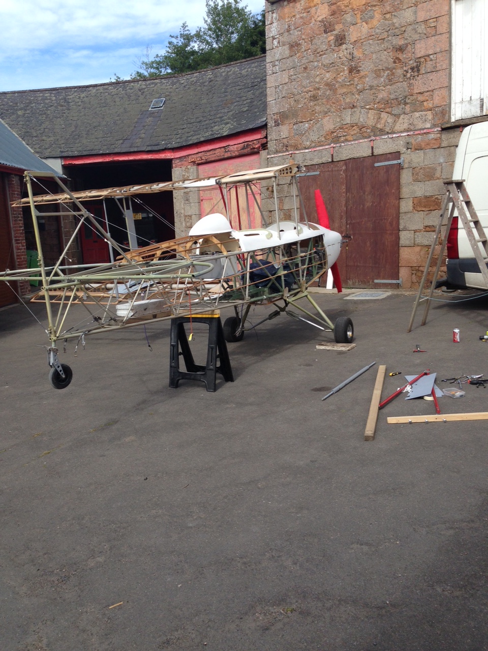
 

Ariel location and ground plane – Hold that thought ! – See next post

Been thinking about where best to locate this and almost settled on rear body somewhere with the ground plane bend to the inside curvature of the body when Mike (my wizard engineer) popped around yesterday.

I took the chance to get some other ideas and he suggested on top of the centre section. This could be handy when pulling loops (once LAA approved of course !) as it would give you a nice straight line to line your reference point on 🙂
A quick text to Adrian (my electronics guru, who very kindly answered my Sunday text) as I thought the ground plane may need to be curved but he assured me flat was OK.

IMG_0127  IMG_0126

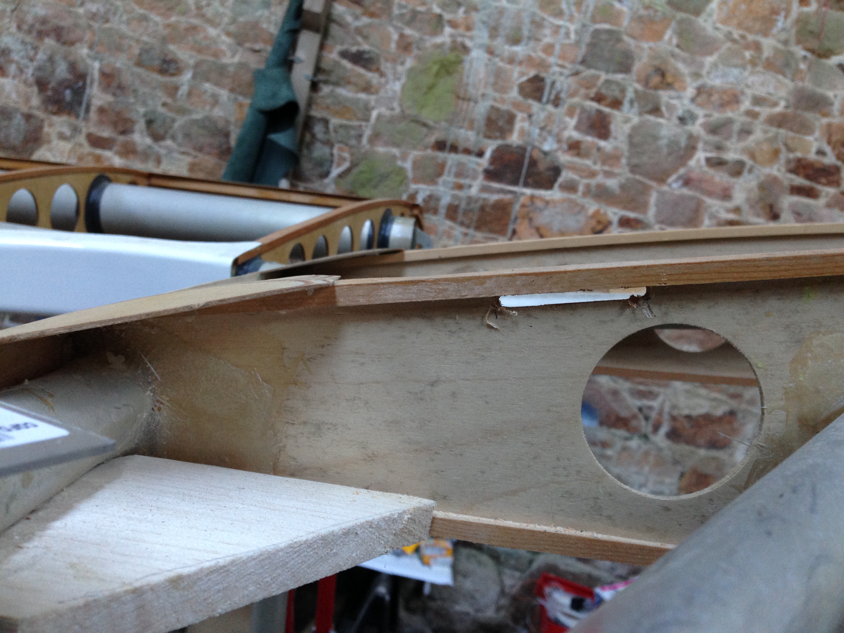
Slot cut to accept the ground plane.

IMG_0130  IMG_0128

Secured with a small rivet and support washer each end.

The plan now is to get some countersunk steel bolts to go through the 3 Ariel mounting holes and into rivnuts so they can be fitted ‘blind’ and also aid any future servicing.

The rake of the Ariel means I will see about 50% of it from the pilot seat I guess.

Battery support

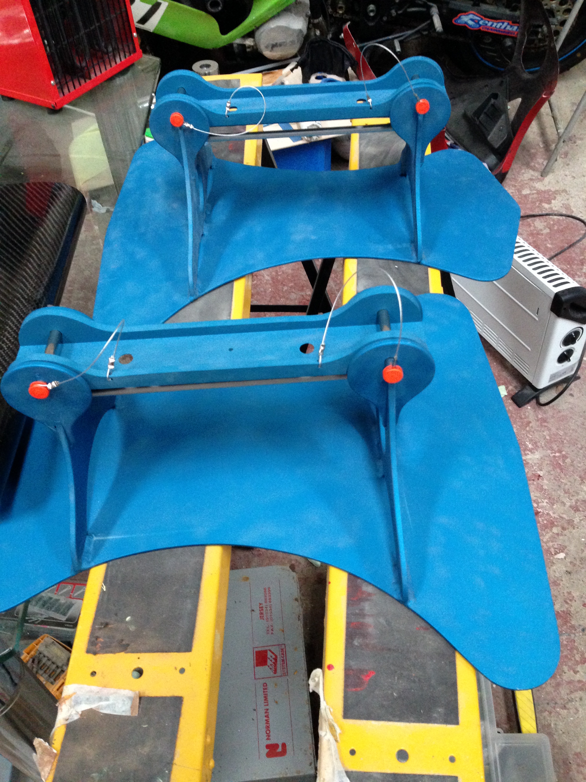
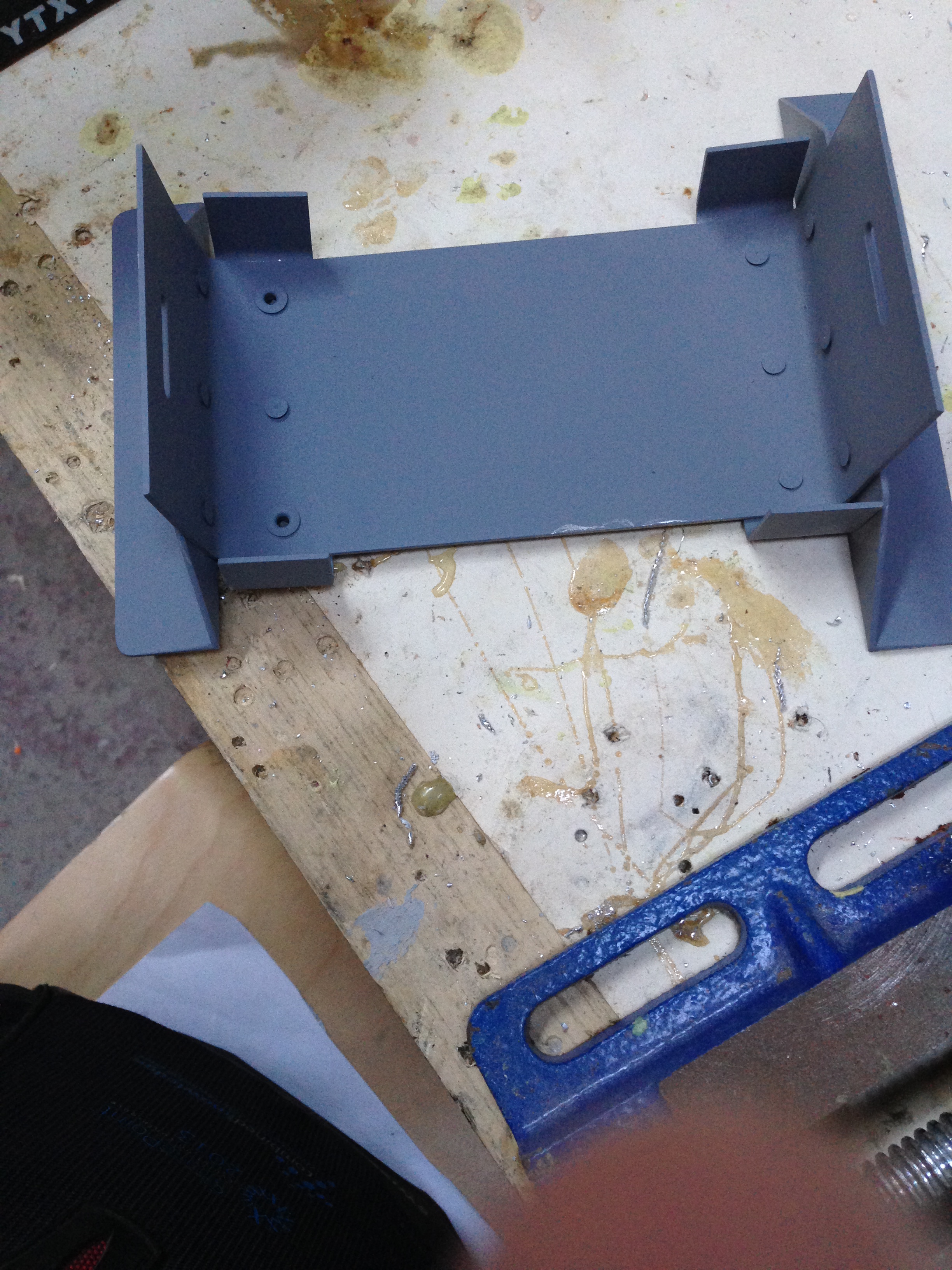
The TLAC battery support kit supplies all you need to build a neat little very secure battery container. It consists of a few pieces of pre cut pilot drilled alloy which, once folded together and riveted makes a nice tight fit for the battery.

This was my first use of solid rivets but pretty easy to use and quite neat.

IMG_0121  IMG_0122

IMG_0123  IMG_0124

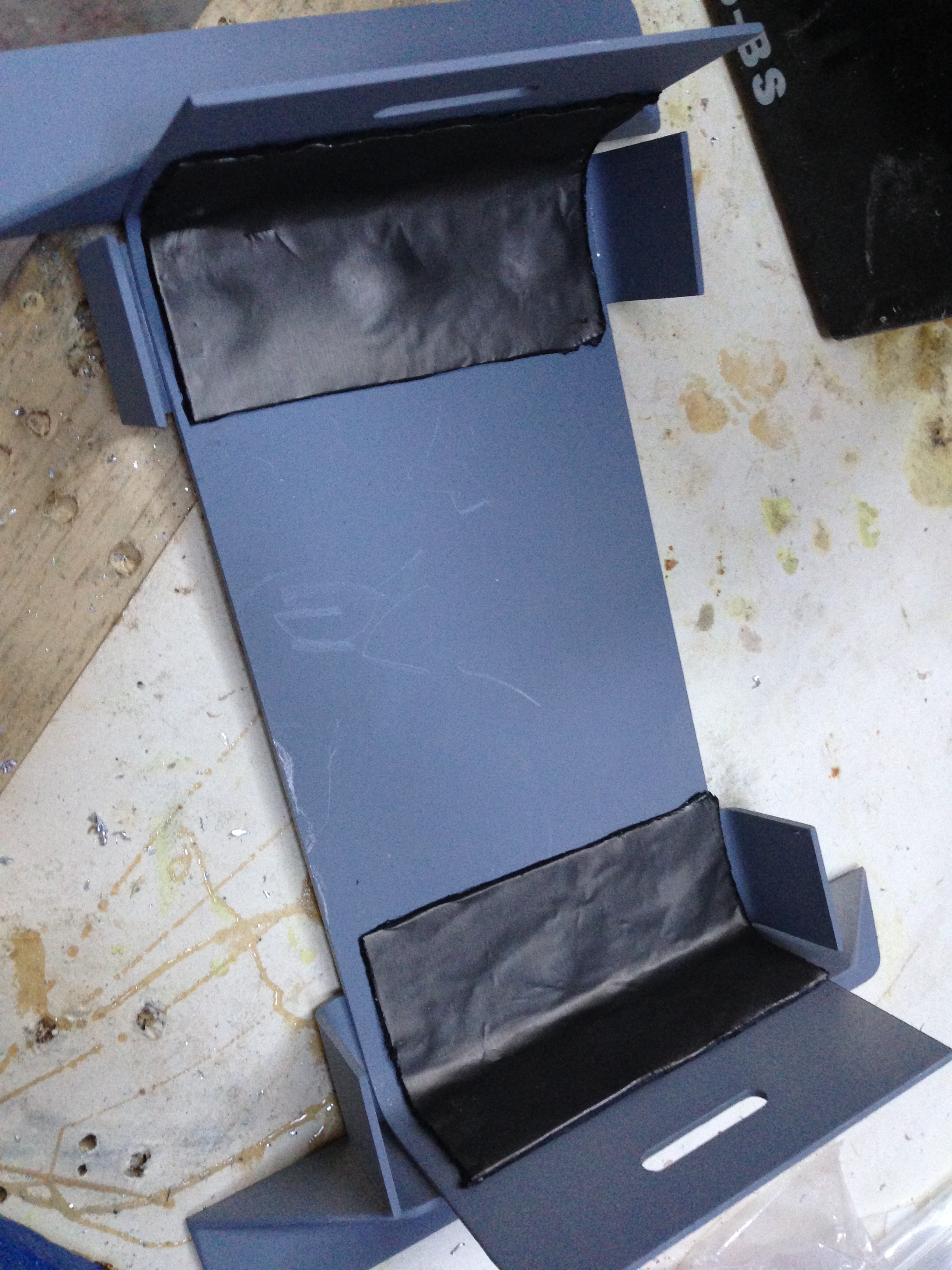
I finished the unit off with etch prime then added some thin sticky back flashing material that would further prevent chafing.

IMG_0125

The UP’s !

Well .. after my low … I managed to get a good long session last night at the barn …


Keith – the barn owner – was superb and helped me get the ‘plane out and completely cleaned down .. ladders, pressure hose jetting of all the little nooks and crannies and then a really good sweep down of the barn.

Then carried on with securing the front lower wood longerons that I had missed from the plan (thanks Danny B for advising !). I used a slightly thicker piece of wood so needed to get some longer rivets and make up the alloy brackets to fit snugly against the inside cheek of the cowl. These will be riveted once all set.

IMG_0103

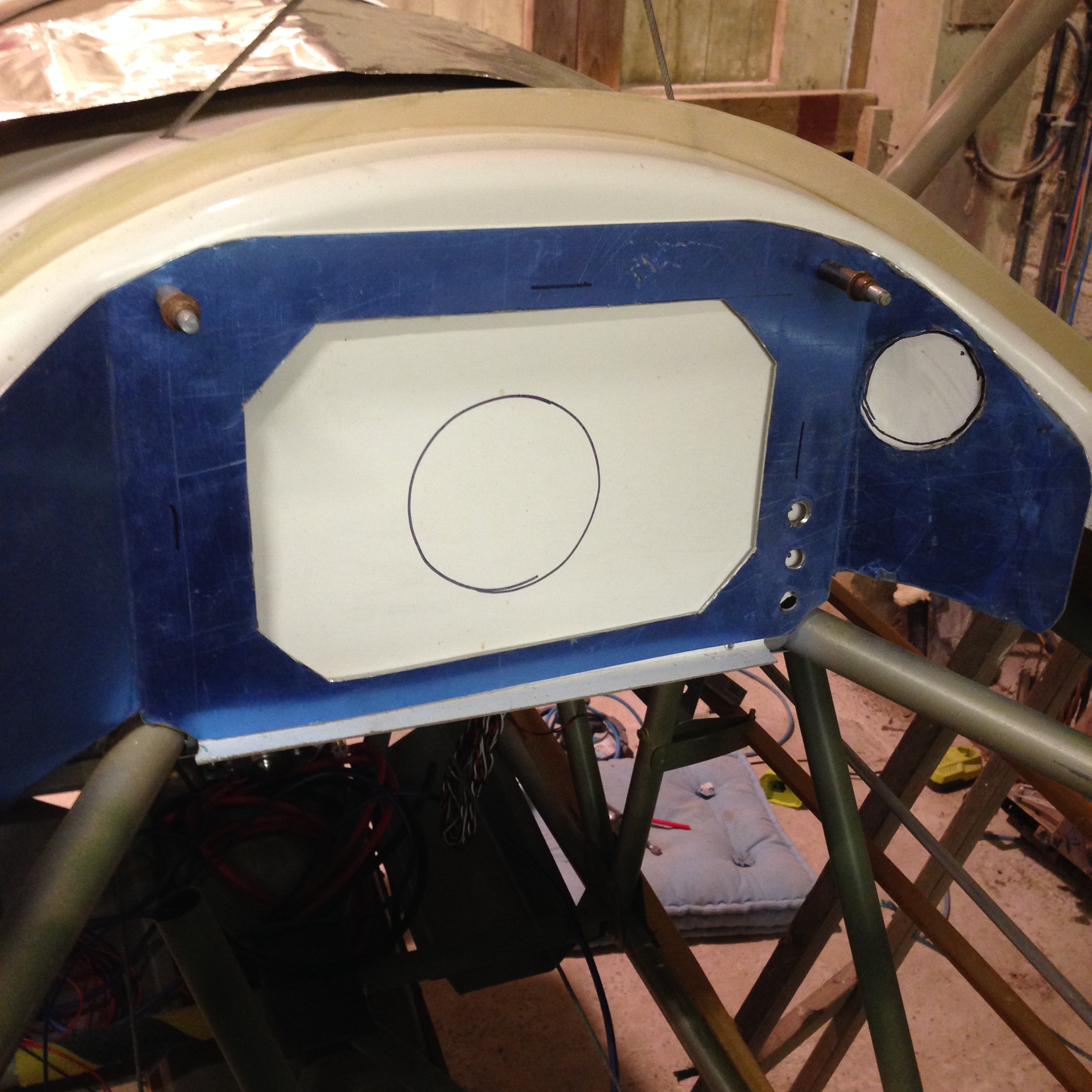
Then moved on to drill the panel positions for the headset sockets (front and rear). Stupidly made the first pairing too close, aesthetically it looked good on the panel BUT I should have realised that the rear fittings on these are relatively large and so should have had a slightly larger gap between them ! No probs, re-drilled and then filled the hole – extra weight saving eh with a drilled panel !!

Anyway, both pairs drilled and fitted. Just need a Trig unit now !

I also got some alloy strip 1m x 35mm x 2mm to act as my Ariel under mount. This will be fitted this week once I decide final resting place for the Ariel… feels likes it’s getting serious now 🙂
All the tail end paint, glue, iron and covering was delivered to my son at Williams yesterday .. just a couple of days too late for me to pick it up following my Oxford puppy pick up on Sunday ! ah well – best laid plans ….

Plan is to now ship this to our London office and I will fly it back next time I’m over. Future ones I may ship through to mainland France and then hop over there to get it. The wonders of living on an island !

This morning – pulled the pitot cable through the drag spar hole I had made.. presenting it forward of the wing joint.

IMG_0104

Just checking with SmokinAirplanes to see if I can position the oil valve at the rear (so easy access behind P1 seat) running the oil pipe to the pump mounted at the bulkhead. Scott is great there as he usually gets back in under 24 hours.


The highs and LOWS

Went away for a week to France for a short break and although I sneaked a load of Sherwood stuff into the roof box I couldn’t get too much done without the workshop.

You have many highs building a ‘plane and I document all of these in the blog … you equally have quite a few lows but these don’t always get noted 🙂

Now, as we enter June, and I am well into the final stages of engine setup and pre covering prep I have hit a series of lows …

  • Getting a simple tin of paint to this island is beyond belief
  • Its easier to build a solar powered aircraft from scratch and fly it around the world
  • No one but no one will ship here
  • So we are left with crazy options to try and ship it to point ‘A’, then hope that the next time I fly across i can meet up with it and fly it back to point ‘B’
  • Then shippers move it a few hundred miles then stop for 3 days so plan A goes out of the window, now, worse, the good are going to point ‘A’ and you have no plans og going there in the near future. The frustrations are immeasurable !
  • Then you go to visit your beloved build after your week away and find that the barn roof seems to be being renovated and no one told you
  • You now have an aircraft that is covered in lichen, half an inch of rubbish from the old roof and inside all the controls and ailerons and body and ….. argggggghhhh
  • Getting trailer parts back from the UK has got held up in customs at both ends  … Saddam never had this trouble shipping his tubes from Teesside !!
  • Wrap is proving difficult now trying to source someone who can turn my photo’s into a film to re-apply post covering – I don’t want to give the option up …but ….

You can cope with the odd one of these, that’s just the nature of building .. but when they stack up and slow you down so so much …..

Oil dip stick access

TLAC made a superb job of their oil access pop up on G-TLAC and I wasn’t convinced mine would look as neat and, having gone through the pain of over trimming one top cowl, I opted for a slightly different approach.

20150517_212127  20150517_212819


20150517_213104  20150517_213705

This involved drilling a pilot hole to check that I was directly over the top of the dip stick and then widen this to take account of the larger diameter alloy petrol cap.

20150517_214657  20150517_214708

The dremel came into its own as the hole was neatened to accept the fitting.

Although I knew the flat nature of the alloy cap would require a small amount of filler to make up the slope of the cowl it all turned out very well. The filler will be smoothed down to ensure a streamlined finish then paint with the top.

20150519_222125  20150519_231111

Made up a supporting alloy ring for the underside – The fitting comes with a cork ring but no metal backing as I guess it assumes you are fitting it to a car.

20150519_224200


20150519_225640

I now simply pull the flap, half turn and out pops the access. Simple and easy to get.

Oil tank shelf in

Completed the brackets and support bolts for this.

The bolts fitted are left over from the build but will be changed to slightly shorted ones and also will fit rivnuts as rear access (once covered) wont be quite so easy !


20150510_172353 20150510_172348

The shelf has been designed to be removable post build in case the tank needs to be removed but also to facilitate regular / scheduled maintenance. The idea being, that you simply remove the two leading bolts and the whole shelf tilts to allow ready access to all tubes, joints, breathers etc

20150510_172343

The tank brackets supplied need to be mounted at opposing ends to ensure rigidity. These have pre drilled holes that match the presunken threads in the tank in various locations to provide a variety of securing options.

20150510_181609  20150510_181551

Looking at the location of the forward bracket I should still have ample room to secure a small alloy lip to allow the Two Trig base units (Radio and Transponder) to sit safely and with easy access behind the seat.

Last Swaging ? and Wrap Photos

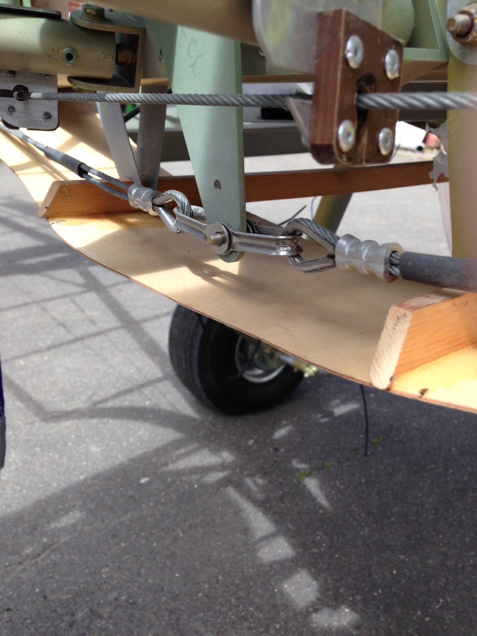
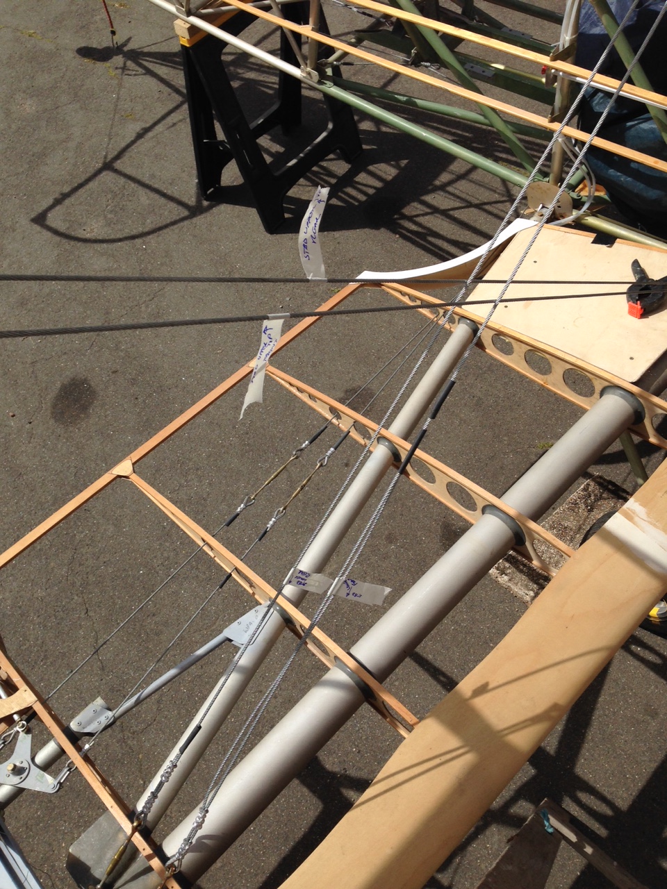
Completed the re-fit and re rig of the starboard wing. The cables had to be replaced so jigged on trestles and re-cut

20150510_165231  20150510_165247


20150510_165239  20150510_165253

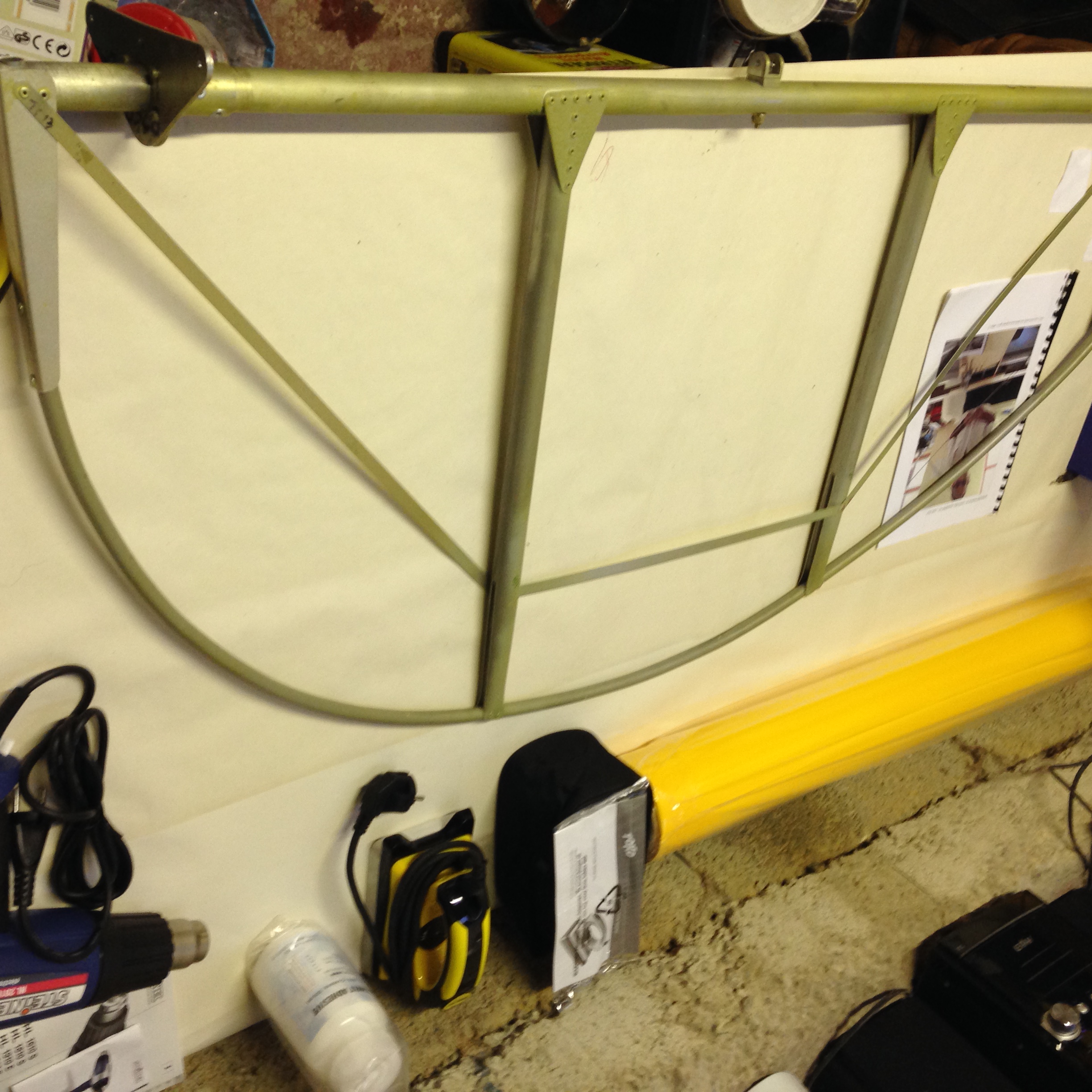
Then down on the tail for some photos. We had a white back board and Sam was taking shadowless shots so that we can try to get the underlying framework put on a clear wrap to post add top the Oratex. That way you should be able to ‘see’ the lovely framework that would otherwise be lost under the fabric. Fingers crossed the idea works 🙂

Tank all strapped in now

Packed up the padding support (care of Williams F1 thanks 🙂

20150506_203445

The metal plate you can just see bottom right is to stop large footed passengers kicking the fuel tap and sender at the bottom of the tank 🙂

And now secured with metal straps and self tappers.

Smoke tank support shelf

Needing to get LAA 9G approval, I have added a very strong support bracket for the Oil tank shelf. The aim is for this shelf to act as a location for the remote Trig Radio and Transponder units.

20150506_204855  20150506_210702

The pipework, like all before is internally treated as well as cracking open my now very crusty Duralac

20150506_222053  20150506_204846

Easy to access via P1 seat

Blog at WordPress.com.

Up ↑