Aileron connections

Now the wings are properly located with pins etc (and NOT going anywhere !) I can finish off the aileron connections. These are crimped in the normal way with Ferrules and Thimbles (slacken off the turnbuckles first to allow you to take up the slack).

ail run 3

Then check the run lines … I have noticed I will need to slightly extend the rib lightening hole so that the cable doesn’t catch.

ail run 1

The primary connection runs through from the bellcrank to the lower arm on the bottom of the Control Column. These are pinned and washers ensure a smooth fitting.

ail run 2

The next stage is the ‘Closed Loop’ cable which runs between both opposite bellcrank ends. This needs to run through cable guides (prepared ages ago !) that direct the cable across the body underside and ensure the run does not foul the other cables.

TLAC – Wing root finishing

A few shots of what all this wing drilling is heading to. A picture is worth a 1,000 words (probably 1,000,000 in this case !) Here are a couple of shots I took of the TLAC aircraft on the recent open day… to give some idea of what the resulting wing fittings will look like

wing root TLAC   wing root upper tlac

I bought the alloy root strips so these can go on once trimmed and shaped and the brackets are all completed. TLAC uses a neat spring / stop arrangement to help single handed use when opening and closing the wings. The wing peg is fitted to an alloy shaft but has a pin protruding either side .. this then catches (once turned) onto a small raised alloy right angle bracket which holds it back (ie out) whilst manoeuvring the wing into its seated position.


Starboard Rigging

Having used cable ties to temporarily hold the rigging in place on the starboard rigging in position I have now replicated the work I did on the port wing and swaged and ferruled them properly.

rigging july

Once these are done the wing pair become almost a single unit and (coupled with the jury strut) everything just tightens up nicely.

In the is new state I can consider properly folding the wings back in turn and checking the fit under the fuselage and also the alignment with the tailplane.

One other thing I can start to manufacture is a board clamps that we effectively clamp either side of each wing strut to provide additional security when towing on the trailer. (See picture below from the original TLAC board)

wing board


Final Wing Pin drilling – Team Effort !

Last night saw the final few holes drilled for the port wing, with Mike and I running through the logged routine of prep and drill/boss sequence.

A welcome support member to the evening event was our local Chief Flying Instructor – James Evans.  James immediately rolled up his sleeves and was holding wings, drill bits, lining holes as well as looking at the progress from the last time he saw the build which was over a year ago.

There was a slight moment when, having drilled all the holes and reamed them the bottom wing just wouldn’t align and the pin was slightly out. Eventually we remembered that we had spotted this on the starboard wing where the spar comes up against the main fuselage bracket and has to have a very small notched filed to allow it to clear (once it has settled on its 3 degree dihedral).

spar cut

Notch duly filed and hey presto … the wing slipped into place, the peg fitted like a glove – tight but fully seated and no play. Then the FINAL cross check – although it did look all aligned to the eye ….. out with the dihedral boards to re-check 3 degree bottom, 1 degree top.. perfect…

James had the honour of slipping in the final pin.

James pin

Thanks for all your help guys …. as we discussed last night .. so many quiet nights over nearly 2 years … its great to have enthusiastic and such knowledgeable company .. all of whom are so willing to give up hours of their time to help keep things moving.

Background – do you have to be an engineer ….

Bit of a late entry to the blog .. but may help those wavering on the edge of ‘Should I’ .. ‘ Shouldn’t I ‘ buy …..

My background is not in engineering at all …. Spent my career in IT designing, coding and testing major banking systems to NatWest/Coutts and small/medium sized business systems. For those who know of mainframes …that was my forte .. Assembler 370 machine code (with my mentor Frank) .. A mans coding language !

Worked in the city for 10 years, learning to ‘fly’ on the Liverpool street to Colchester rail link, eventually taking my test in Ipswich, qualifying cross country Ipswich, Cambridge, Sywell, Ipswich… Fun days. Then took a promotion and moved to Jersey for 2 years (and never left !). Managed a myriad of Coutts offices IT worldwide from Cayman through Miami to Zurich, Hong Kong and Singapore. My year 2000 switchover was a very long two days to ensure all offices worldwide were ok.

Learned about mechanics when I bought my 1967 MGB Roadster … 7 years of being able to predict what needed repairing almost before it had stopped rolling from its latest breakdown Then with 3 sons all getting into motor biking we ended up being a 7 bike family .. Track days ensued in France, Magny Cours, Le Mans, Val de Vienne …. I learned exactly what a high side is .. And how much bruising you actually get when your Aprilia RSV decides to break its fall on you !

Was very fortunate to fly my very good friend (Captain John Graham) 1937 Stampe for around 5 years and fell in love with biplanes and their unique features. Annual air tests were always an exciting time.  Jersey Aero Club managed to secure a fantastic old Chipmunk on loan from a Jersey resident (Mike Collett – Owner of The Classic Collection) which plugged the gap for a while when the Stampe was sold.

Now do around 100 hours a year picking puppies up from the UK as no airlines fly them back from the UK now (the long boat journey is not much fun for a young pup – or an anxious owner). Fly to France most months with the odd nip into Paris (Toussus) and various other little strips. Built and flown models for years but stopped when I moved to Jersey… So the Sherwood is quite a step up…. Lots of new techniques learned and new disciplines to pick up.

TLAC open day – Saturday 5th July

What a fantastic show the TLAC team put on … Great company, great food – crackling to die for ! – and a biplane to light up any dull summer day !!

Clearly a lot of effort and attention to detail had gone into the planning and it certainly showed with everyone smiling the whole day through .. Those lucky enough to get up in the Sherwood had an even bigger smile 😄

With my ‘soon’ (hopefully this year) first test flight of my Sherwood I managed to get another flight in with the skilful and genuinely nice chap James … Very kindly gave me it 6″ off the ground so I could refresh my memory of those beautifully balanced and smooth controls. Some lovely banked turn to turn orbits followed by a nice quick approach to he small grass strip. Felt too high so side slipped a bit but wasn’t needed as we rounded out nicely just above the threshold …. Checked and floated along … Then James took her and did a James circuit as only he can …. Fantastic creamer wheeled landing

Many thanks to Paul, Ivor, James, Alastair, Bob and all who took so much trouble to answer my umpteen minuscule questions and hold bits for the photo book … With a support team like this .. Why wouldn’t you build such an amazing ‘plane !

Lots of very close detail photos of the wing fittings to help me refine mine.

Port rear wing mounting bolt drilling

Early trip into the barn this morning – to keep things ticking over – and separated the Port pair of wings away from the fuselage (to gain working space for driling the wing roots). Supported them on trestles.

These were so much easier to move than the starboard ones as I had properly secured the cross wire rigging. This makes the pair act much more like a single unit if being moved. YOU MUST still be very carfeful with any movement so you don’t invoke a twist of any kind. To be fare – the instructions do say to rig first – I had rigged one end and cable tied the other to give me later playing movement. In practice its better to rig it and tighten on turnbuckles as that makes the whole thing much more manageable.

Using the new cut down Boss on the top and Pauls/TLAC one on the bottom – drilled the rears through in minutes


Port wing rear bracket 1  Port wing rear bracket 2 You can see the alignment pin just poking through prior to clamping in position

Finished check that bolt slips in easily

Port wing rear bracket 3

Drilling the wing mounts – Part 2

Last night was an epic move forward … completed the starboard wing mount drilling for both upper and lower …

Definitely a two person job this one …. so, with the expert eye of my trusted engineer Mike Fleming we separated the wings from the body, trestle them up and then got to work on the top cabane rear joint. Mike had made a small boss matching the internal dimension of the TLAC one but with a very slim facing edge so that it could fit against the cabane end rib and completed trailing edge.

20140707_231313 20140707_202246 20140707_202253 20140707_202624

This was drilled through using the same techniques as the previous section on Wing mounts 1

Accessing the front lower spar joint required the leading edge to be pretty much cut to the finished edge. This was done using a fine tooth hacksaw to leave a very fine edge. Having picked up the aluminium root covering at the weekend from TLAC’s open day I now have a better idea of the finish line of the wing root.

20140707_210747

We took some time to offer the TLAC boss tapered edge up to the spar turning it through successive 90 degrees to show that it was most definitely lined up correctly well before drilling. If you have it 90 degrees incorrectly aligned you can see the inserted drill bit angle would mean your wing peg bolt would come out at a complete skew to the rib – so it does make sense to picture the ‘run line’

20140707_205624

Drilling this particular hole with its compound angle takes planning but it does all make sense in the end !

Once the small, then large drill have gone through, the reamer is offered up and run through very carefully. Once you check the pins you will see that they are very very snug ! ie tight …. taking the reamer through past its half way length (its tapered to half way) just takes that thousandth of an inch off to ensure a perfect hand tight fit.

20140707_203350

Accessing the top front cabane bracket proved very tight as well, even with a relatively thin drill and chuck. We considered the options and, with the boss firmly clamped and pilot hole aligned decided we could forego the pre 1/4 inch hole and use the boss to put the large drill through – the reason for this is the large drill has a TLAC extended shaft (taking it up to over 12 inches). This measn we can pretty much clear the leading edge. Mike spotted we would not get all the way through (BEFORE starting to drill) as the chuck would meet the leading edge before the drill had cleared the rear bracket. So – we opted to drill from behind.

Boss on, this worked a treat with constant pressure giving a full continuous swarf as it cut through.

All drilling completed and both top and bottom pegs just going in finger tight it was time to bring the wings back in. They aligned pretty well but the pegs were pretty tight. I then realised we had not put back the dihedral support. So packed back up to 3 degree lower (which enforces a 1 degree upper as the wing strut is in position) and BINGO… the pegs slipped – well very firmly – but nevertheless BY HAND .. into their fully home position … WHAT A MOMENT ! 23:30 🙂

20140707_212728

Above Fig – LOWER PEG

20140707_225126

Above Fig – UPPER PEG – Viewed from below

20140707_231612

Final recheck of both Incidence and Dihedral once both pegs and rear bolts are in position


Drilling the wing mounts – Part 1

Not for the faint hearted this section !

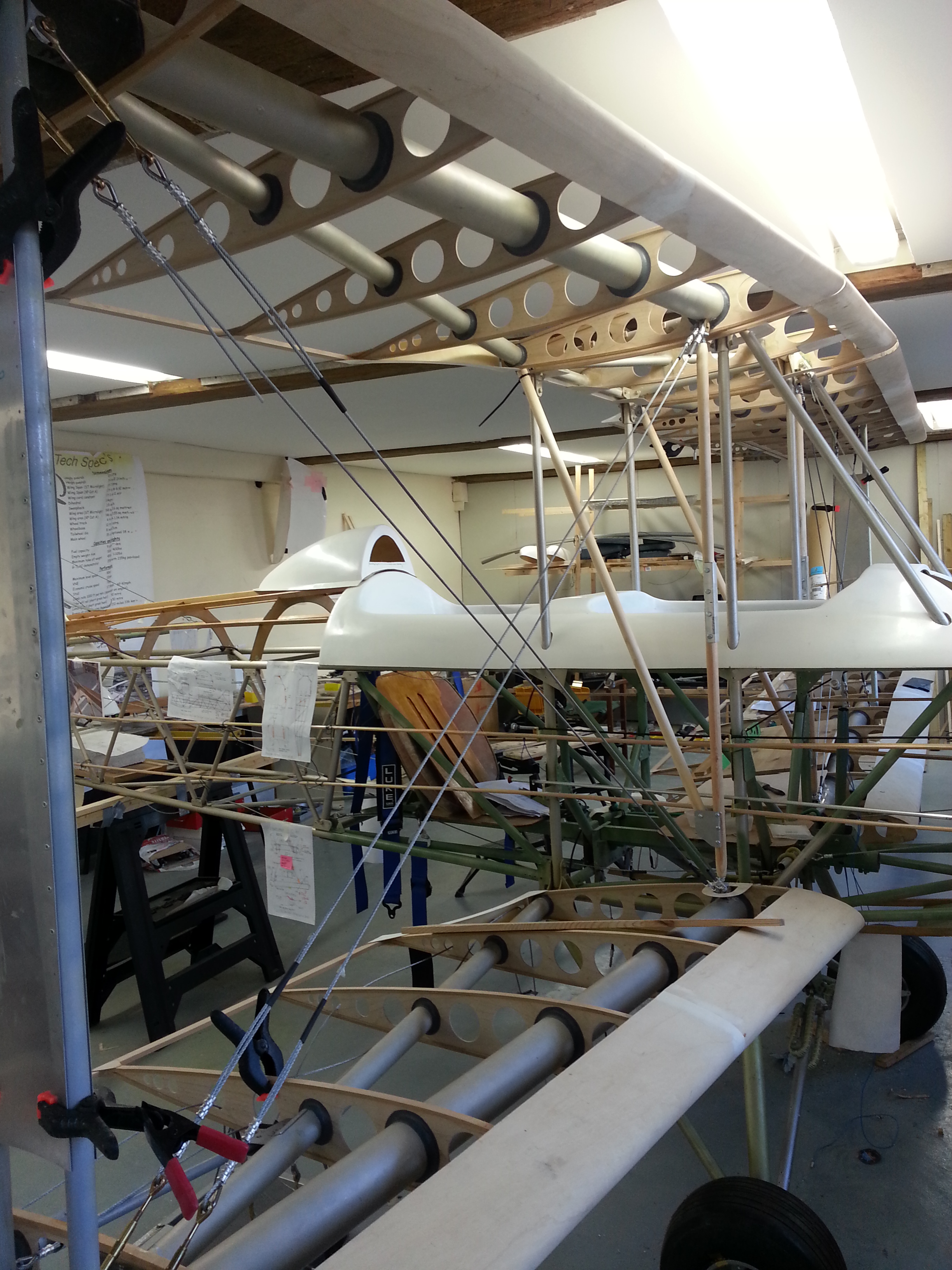
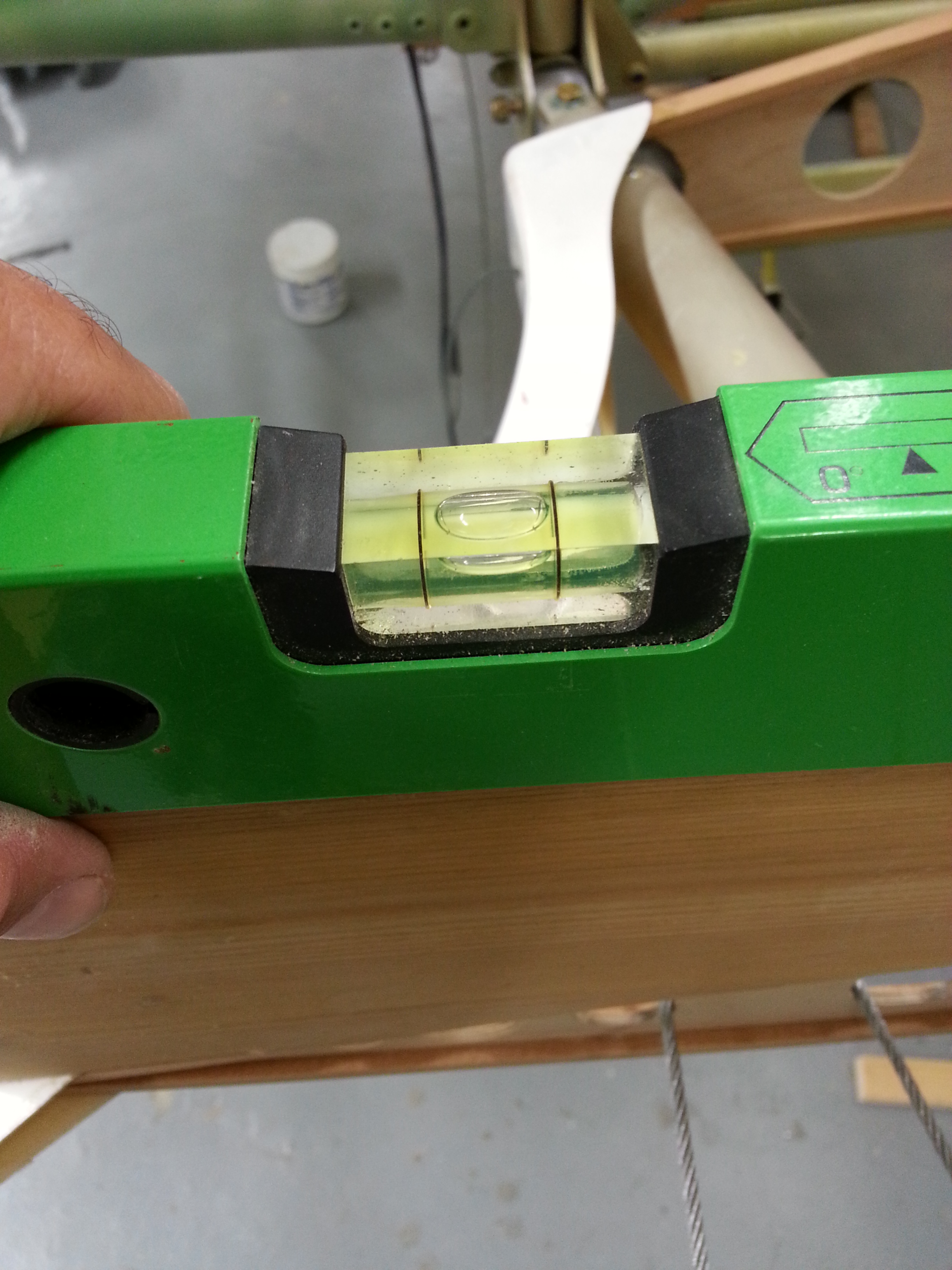
I have lost count of the number of times I have read and re-read the section on wing mounting …. having settled the body with the tail up on a trestle and made sure it was flat horizontal in all planes you can then get the wings set at the 3 degree lower dihedral and the 1 degree upper (see previous entries below).

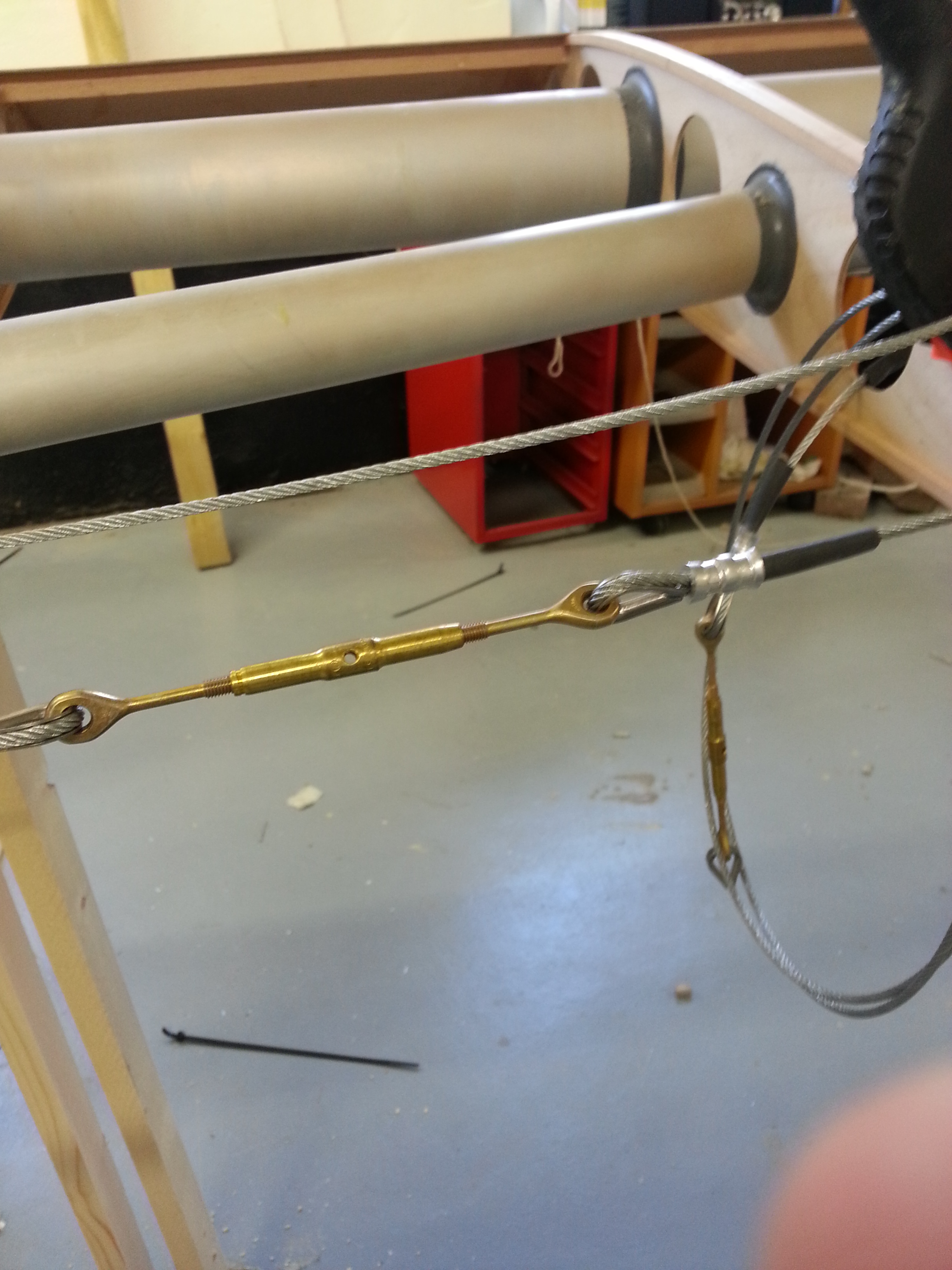
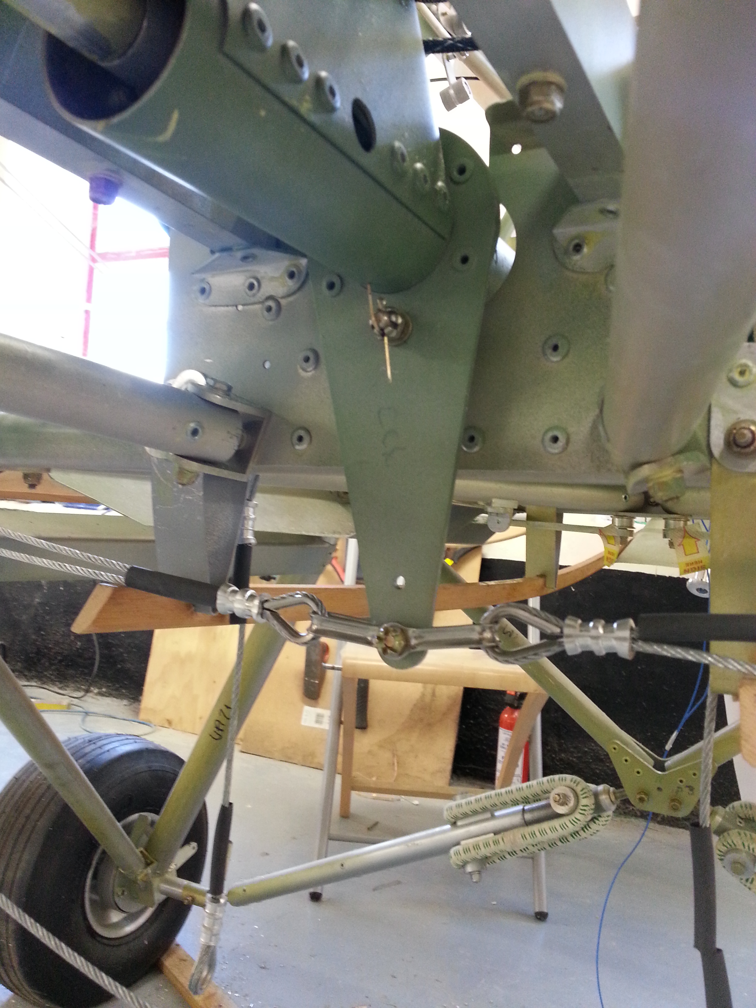
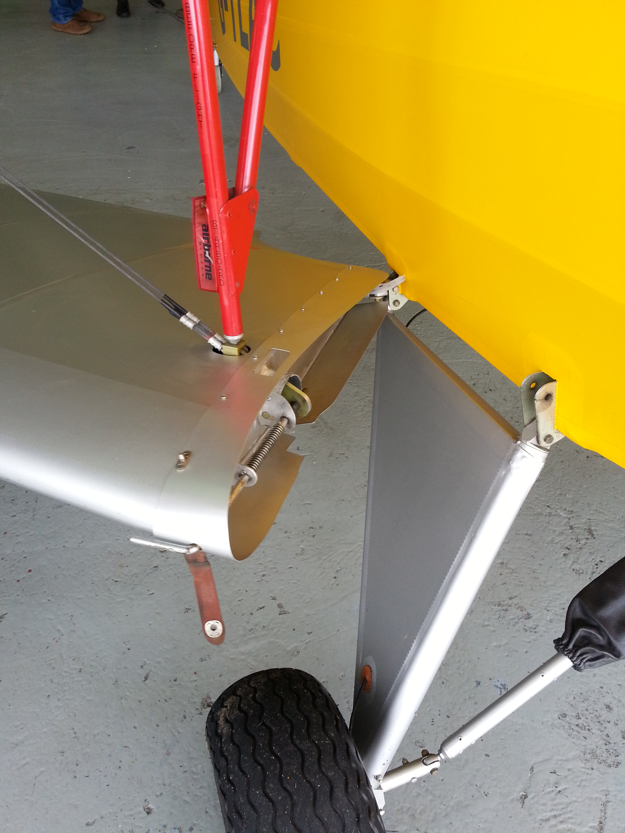
You then need the jury struts in place and supporting as well as the cross rigging of flying and landing wires not tight but firm enough to support the now trapezoid structure. I also went for a roof mounted bungee (or two) to provide a safety ‘net’ in case something gave. This was in addition to floor based 2 x 1 batons clamped either side of the centre ribs in two positions – so in all 4 floor based supports and 2 ceiling based .. You DONT want this collapsing !

Then, with the aid of at least 2 additional helpers you need to part the ‘paired’ wings from one side from the body. This is to open the cap to the root to get working space for the boss drill guide and clamps etc.

Then my 2nd ‘phonecall with Paul at TLAC to talk through I then created a word guide document with pictures of what it might look like BEFORE drilling.

START:

wing drill 0

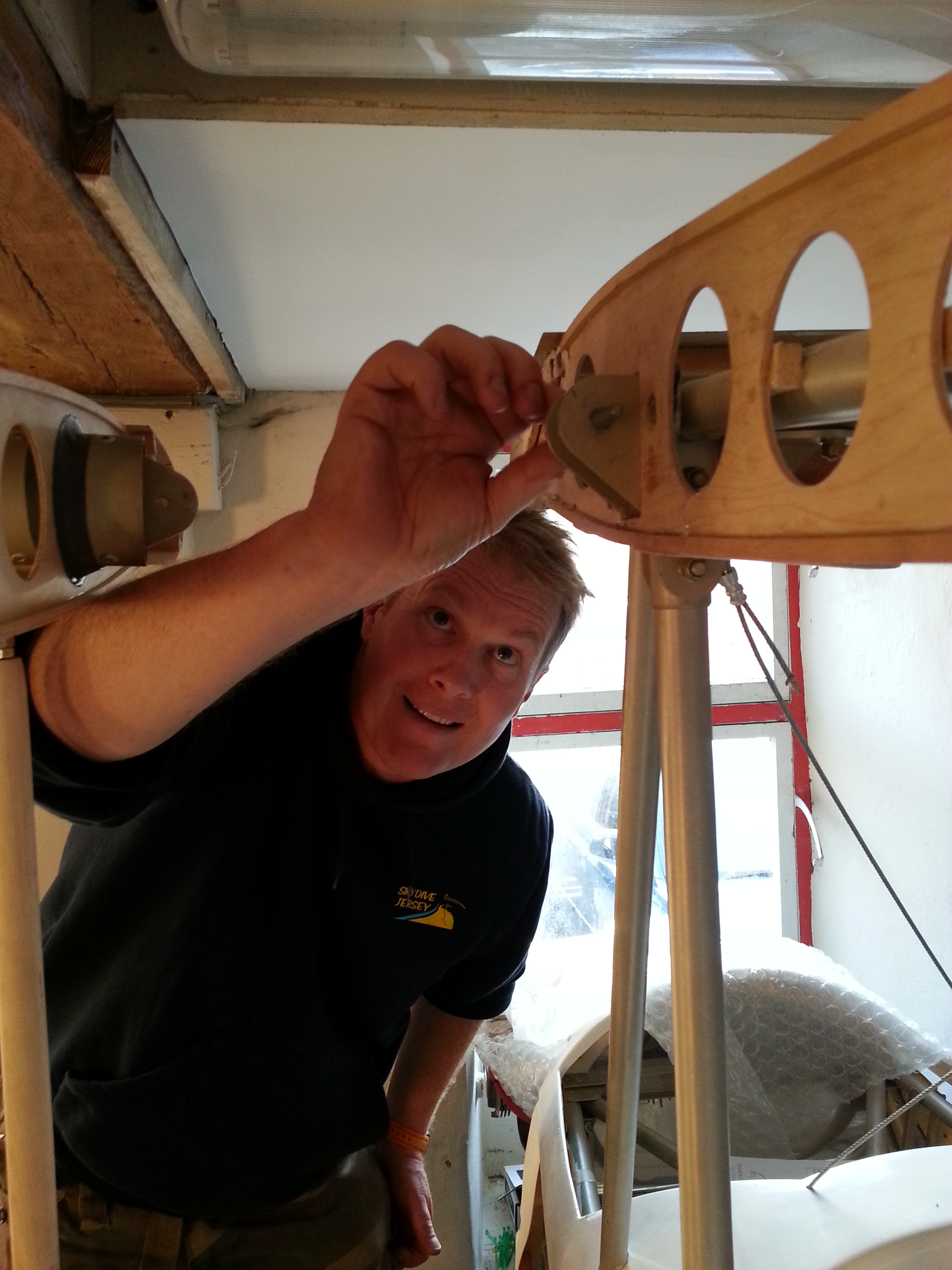
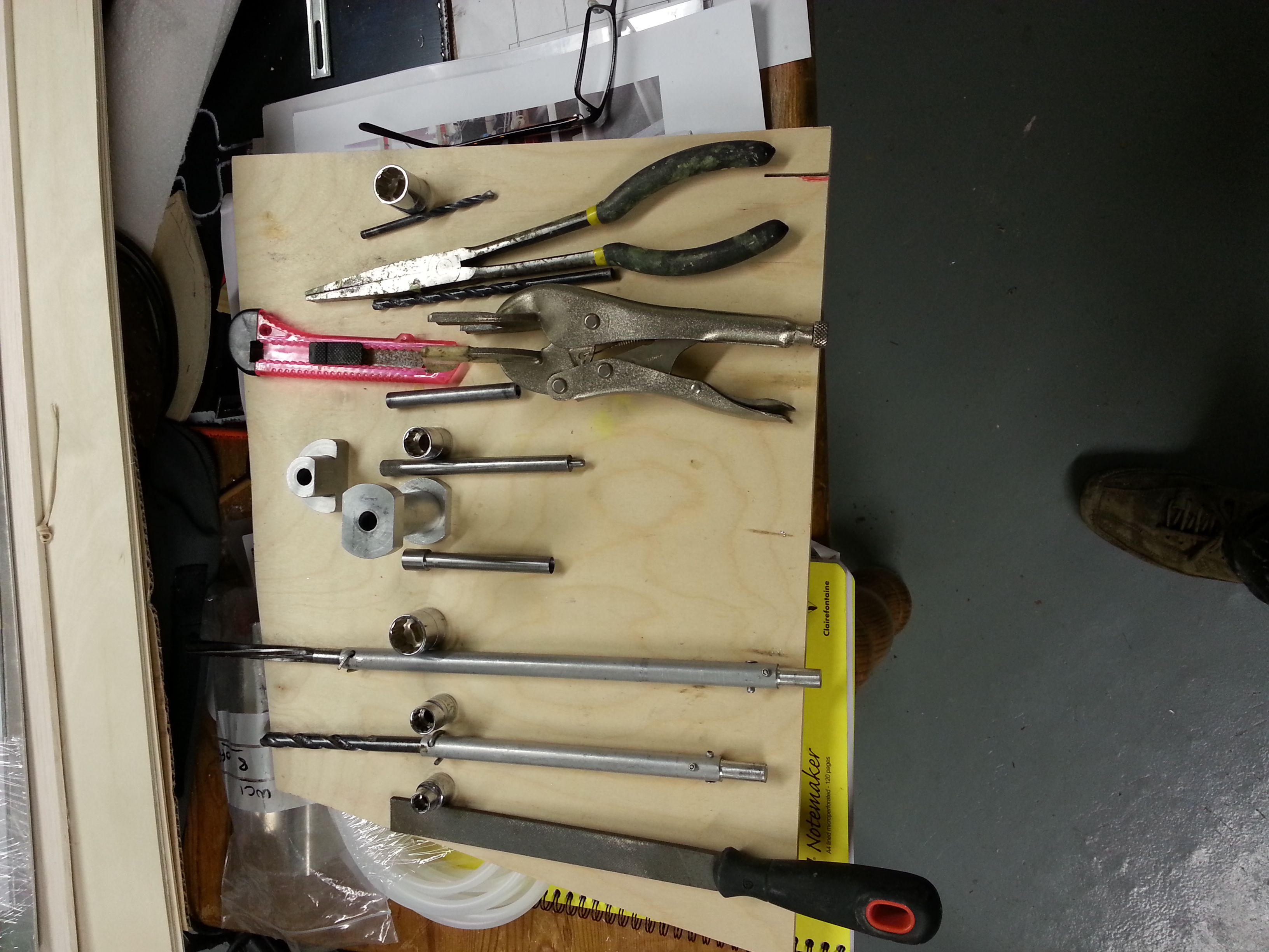
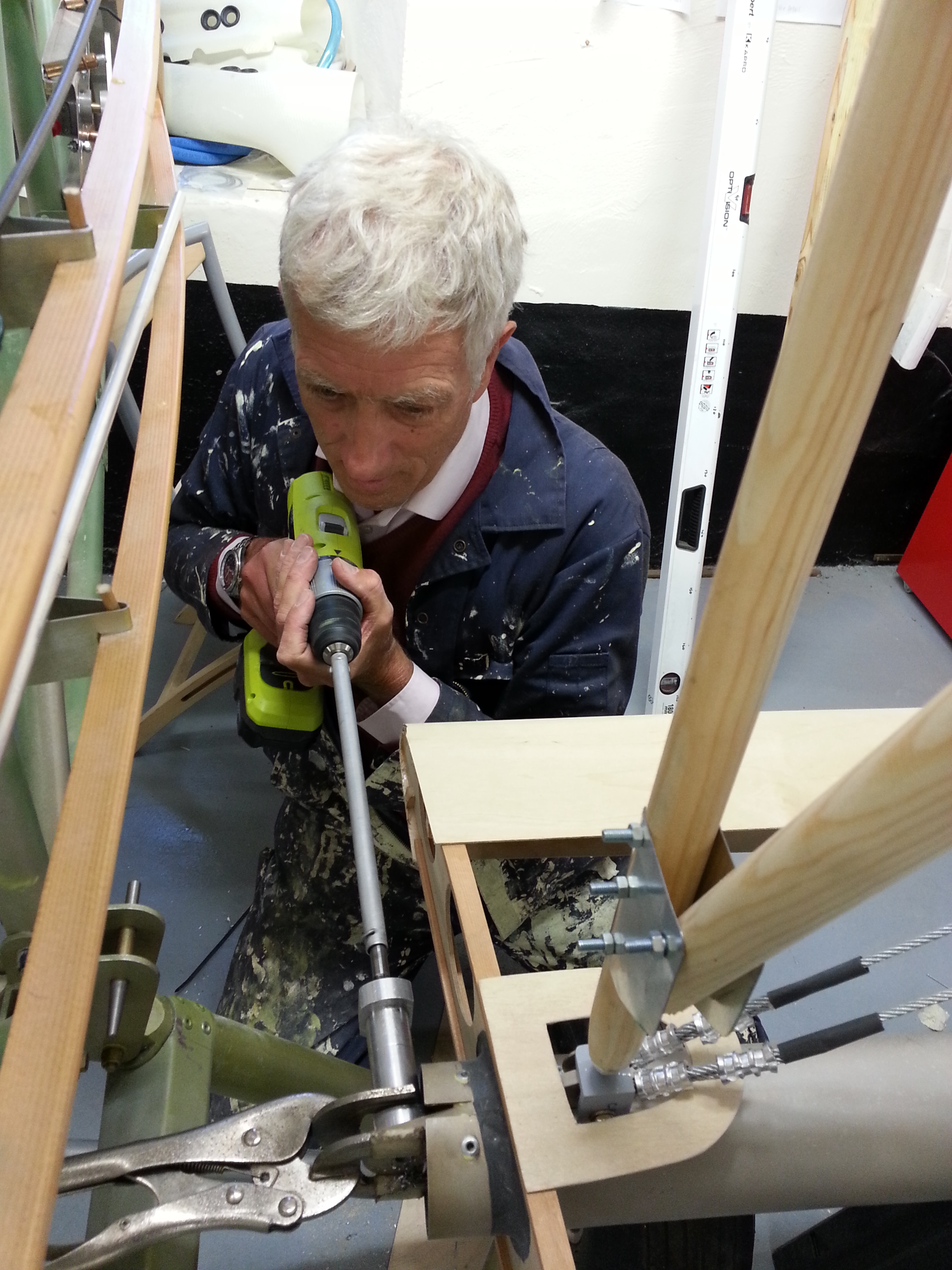
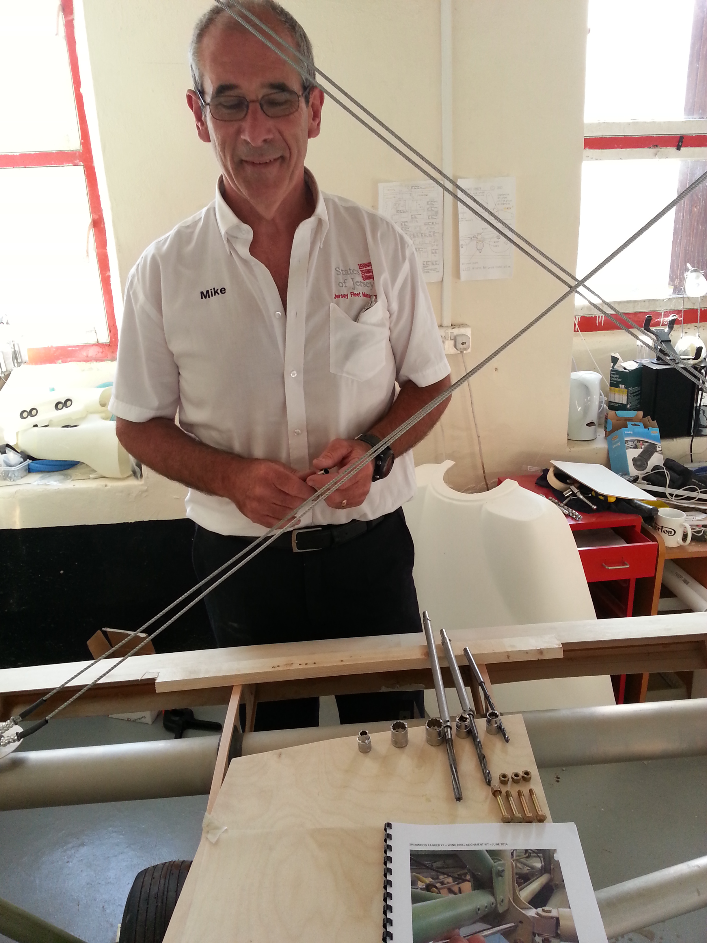
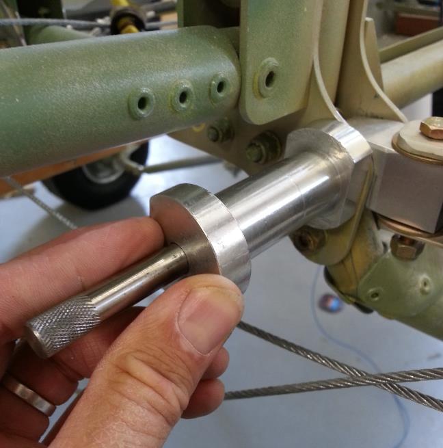
FIG 1: Lay your tools out (My local engineer guru – Mike !)

wing peg 1

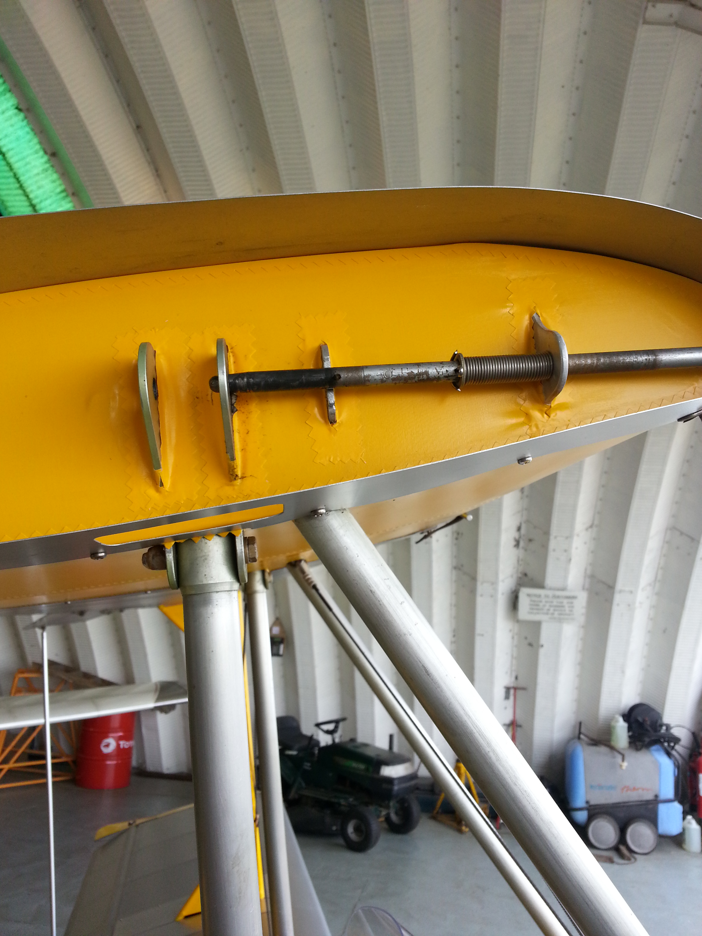
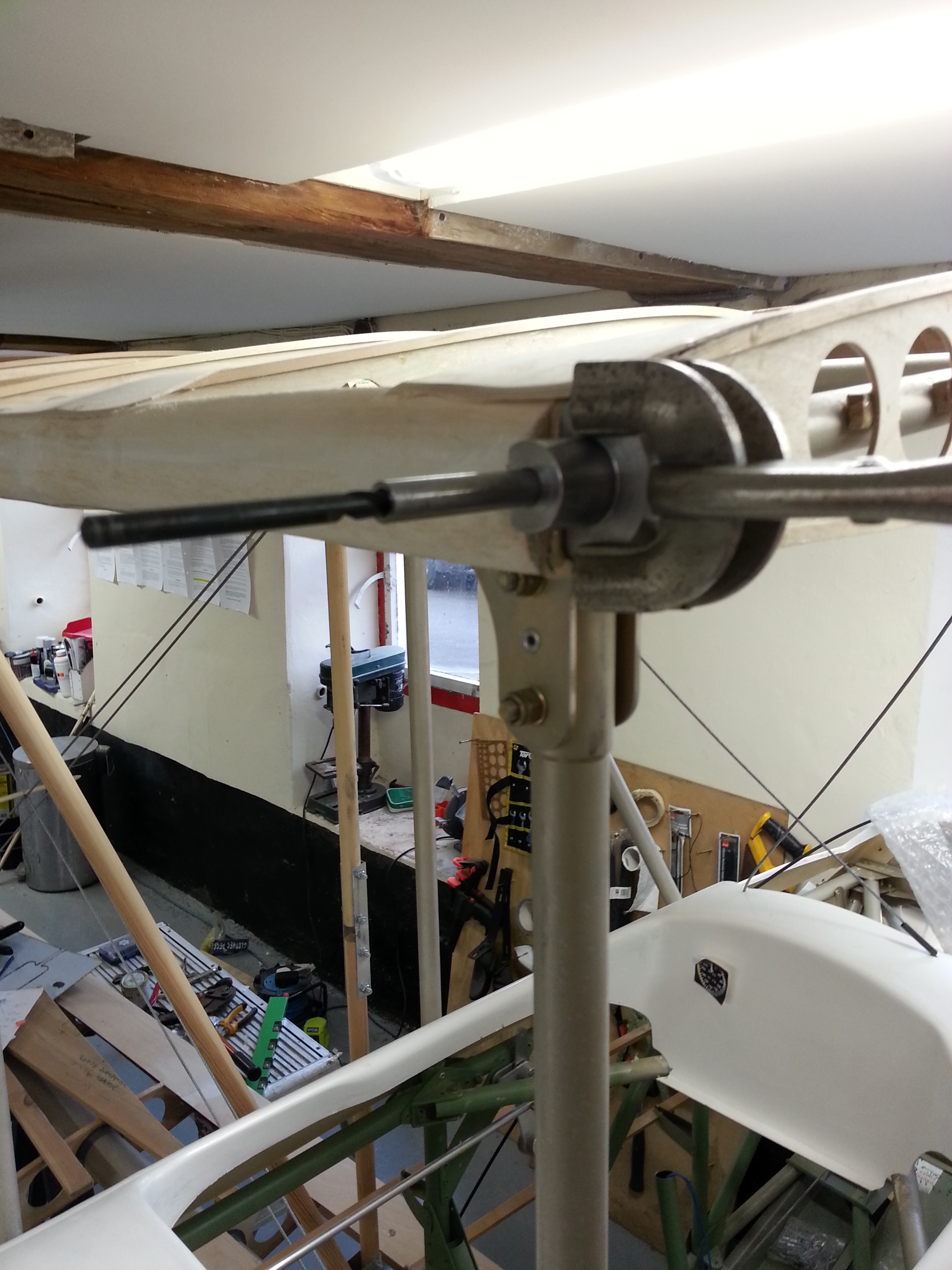
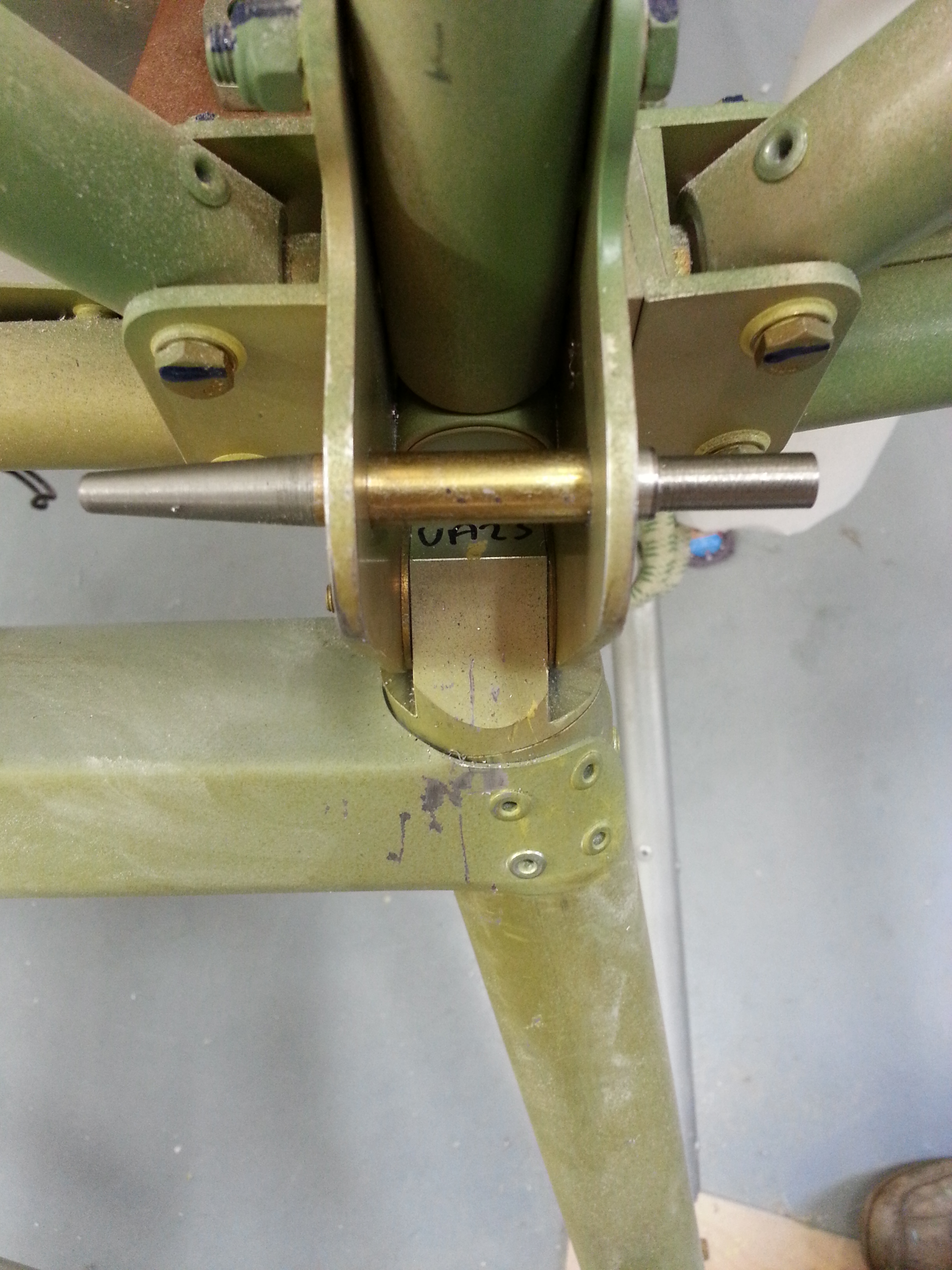
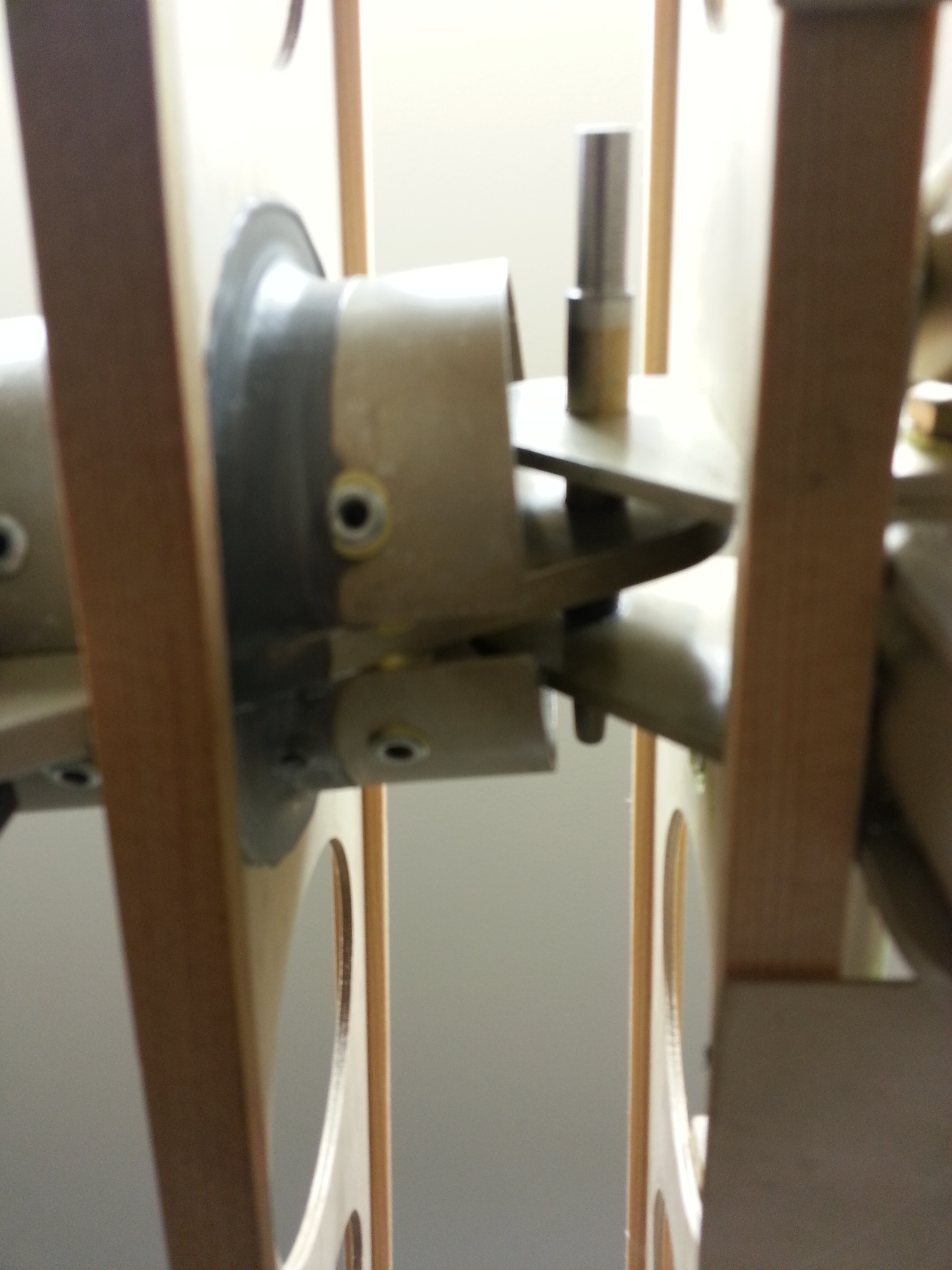
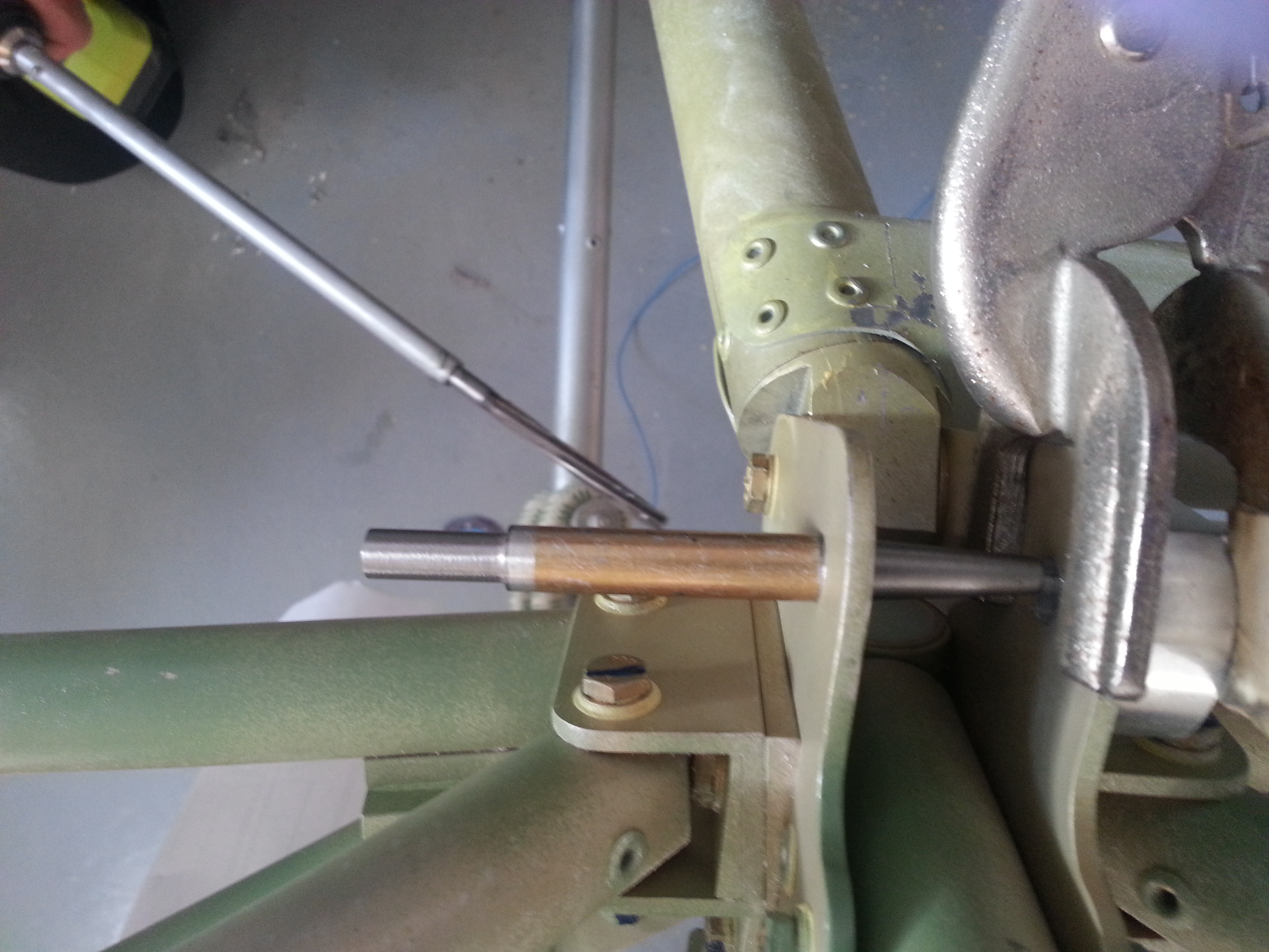
FIG 2 : The alignment peg will be placed through the alignment tool (as shown in fig 2)

wing peg 2

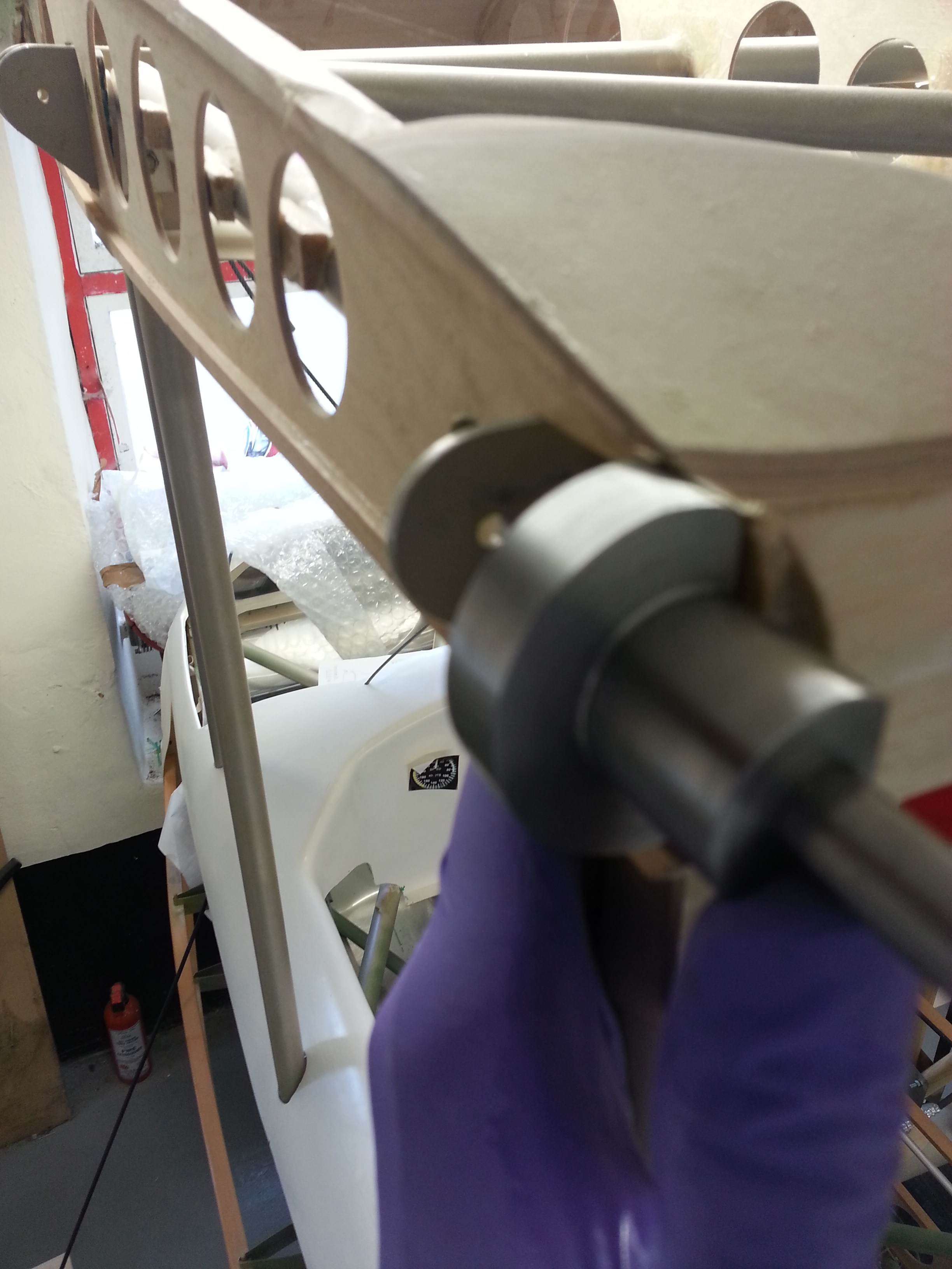
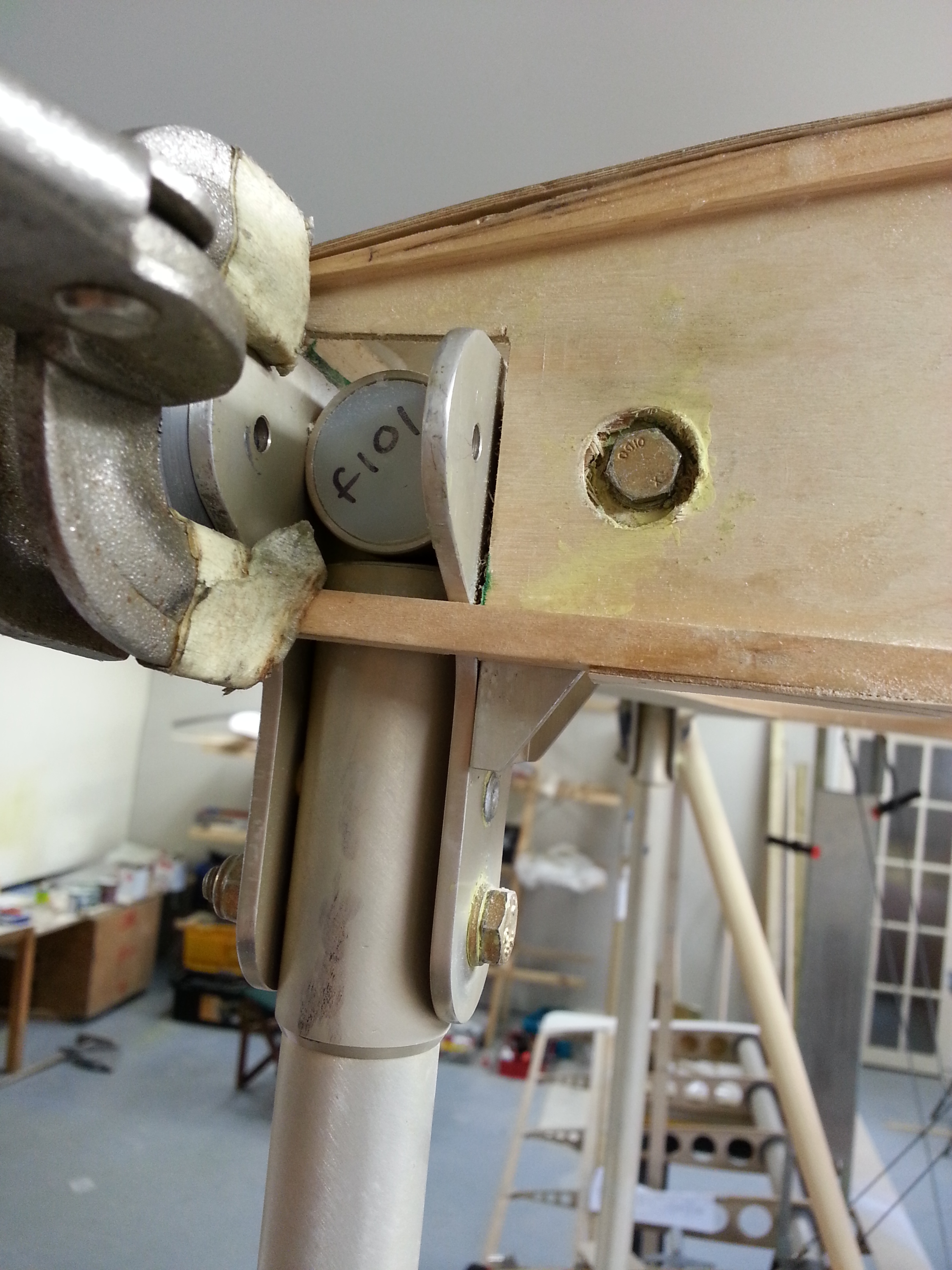
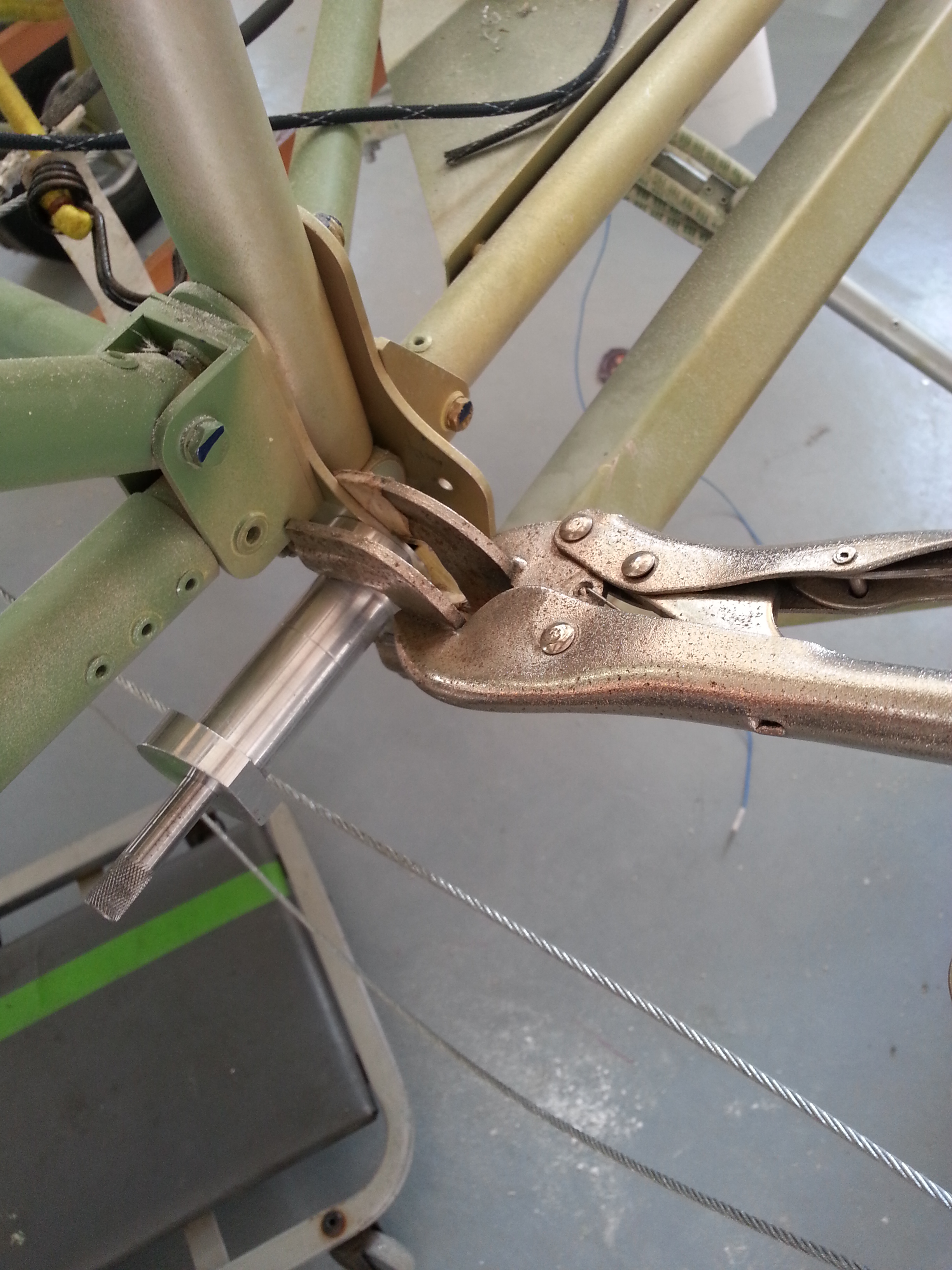
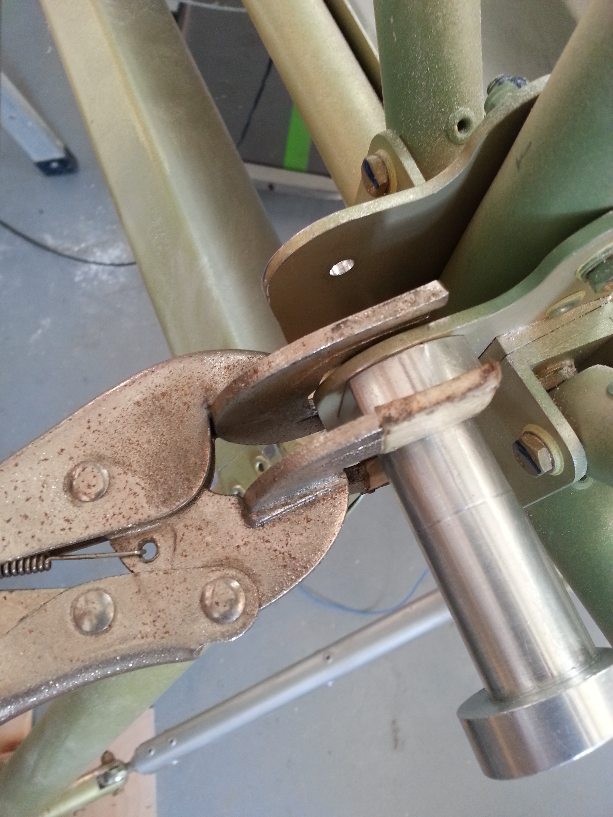
FIG 3 : Place the Alignment bush FLAT FACE on the rear of the REAR bracket on the body at the trailing edge of the wing

wing drill 1

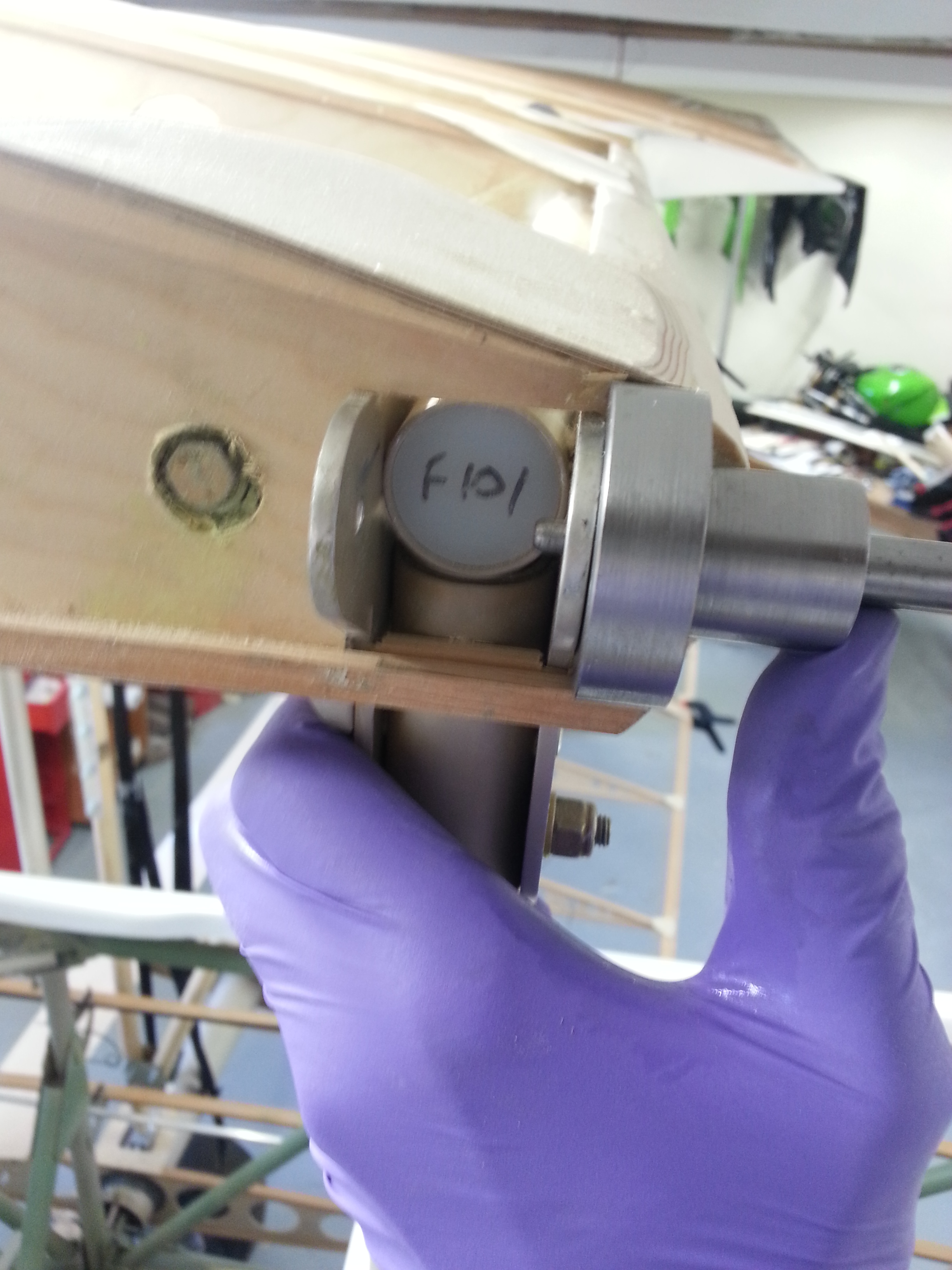
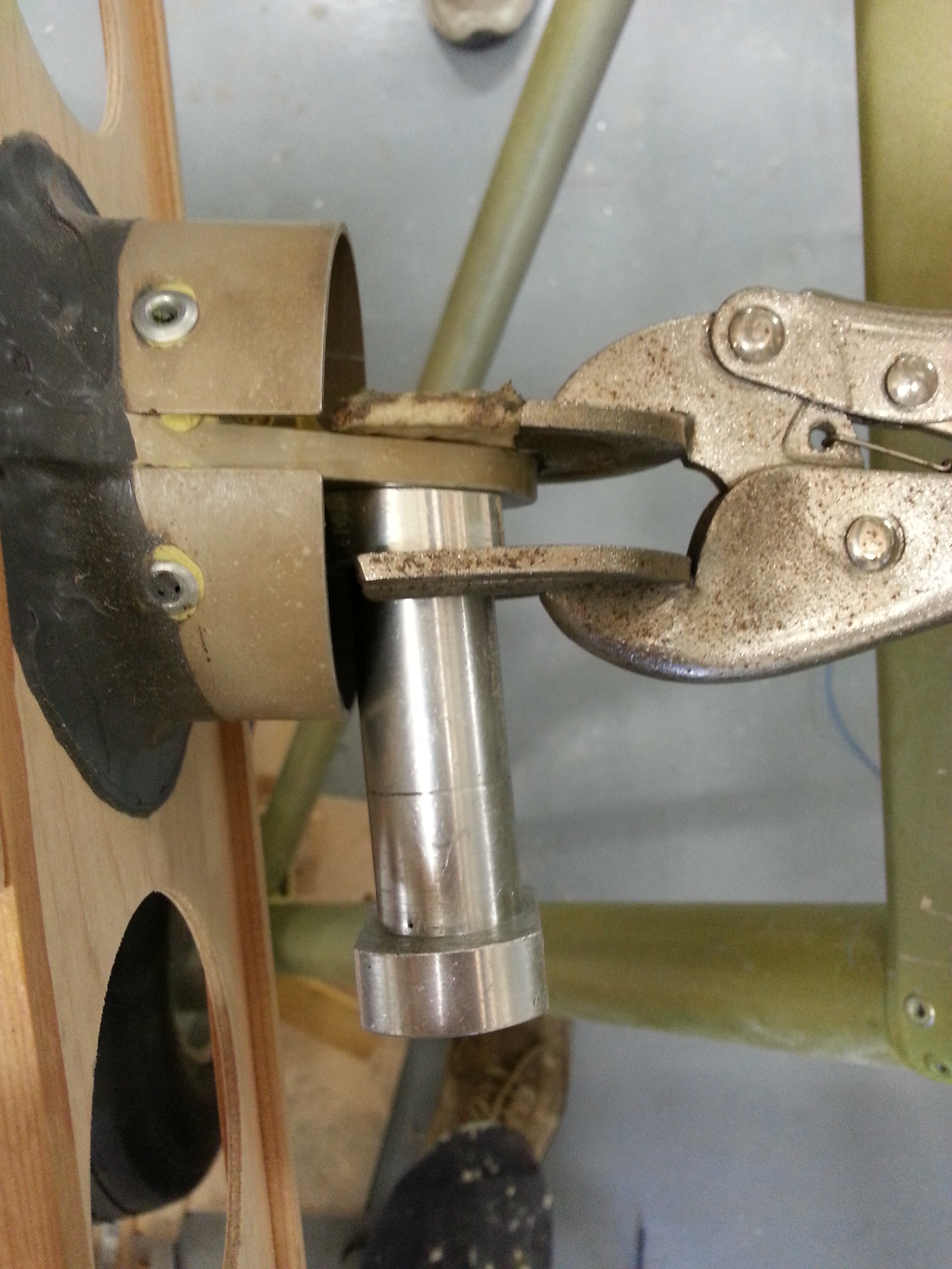
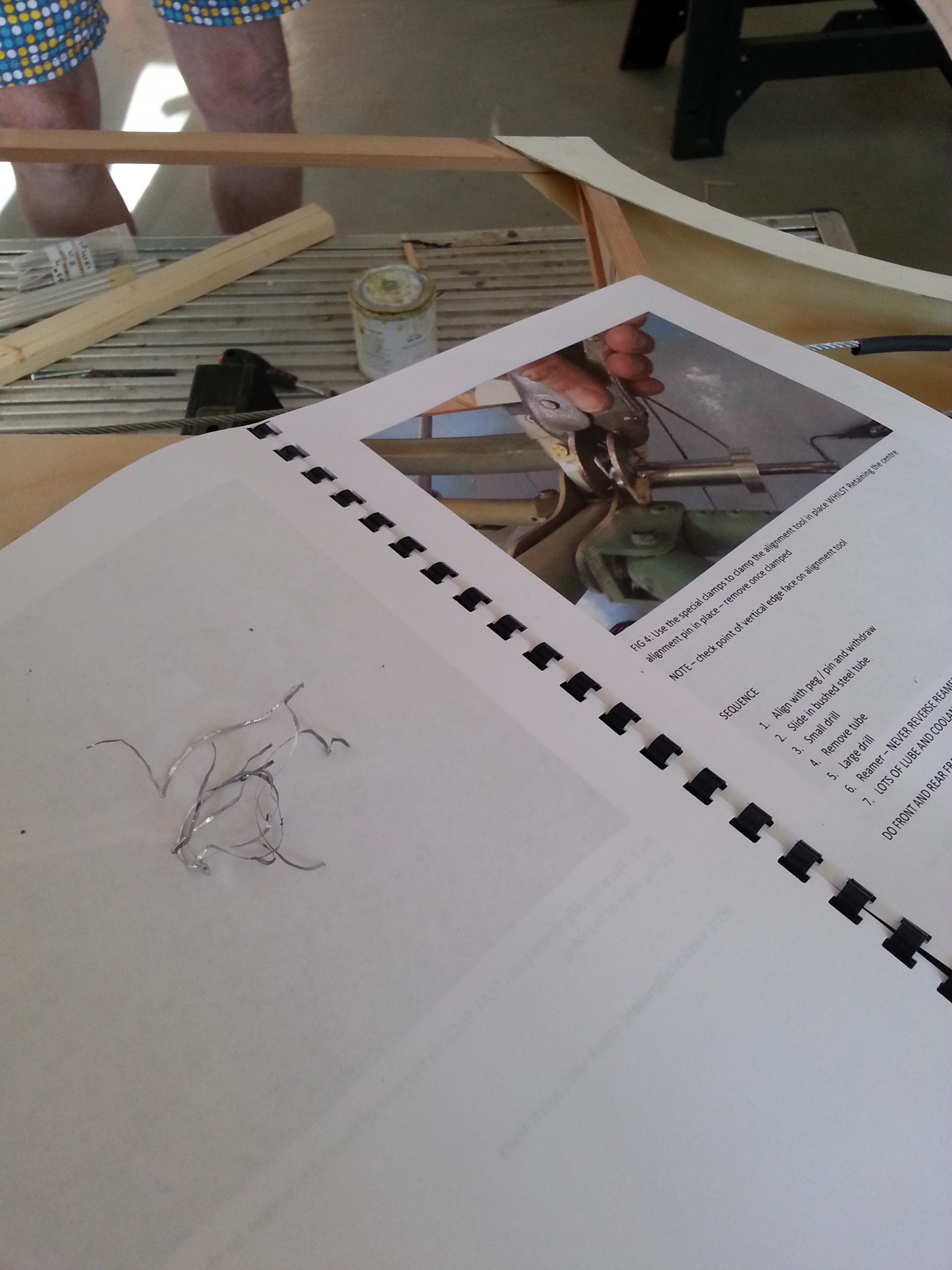
FIG 4: Use the special clamps to clamp the alignment tool in place WHILST Retaining the centre alignment pin in place – remove once clamped

wing drill 2

FIG 5 – Make sure the alignment pin twizzles freely after clamping and BEFORE drilling …. Line of site – eye through to make sure it looks aligned as well as feeling aligned

SEQUENCE ON REAR HOLES ONLY (TOP AND BOTTOM)

  1. Align with peg / pin and withdraw
  2. Slide in bushed steel tube – which fully supports small drill
  3. Small drill – right through – very slowly – even pressure
  4. Take care as drill speeds up towards end to prevent overspeed
  5. LOTS OF LUBE AND COOLANT

wing drill 3

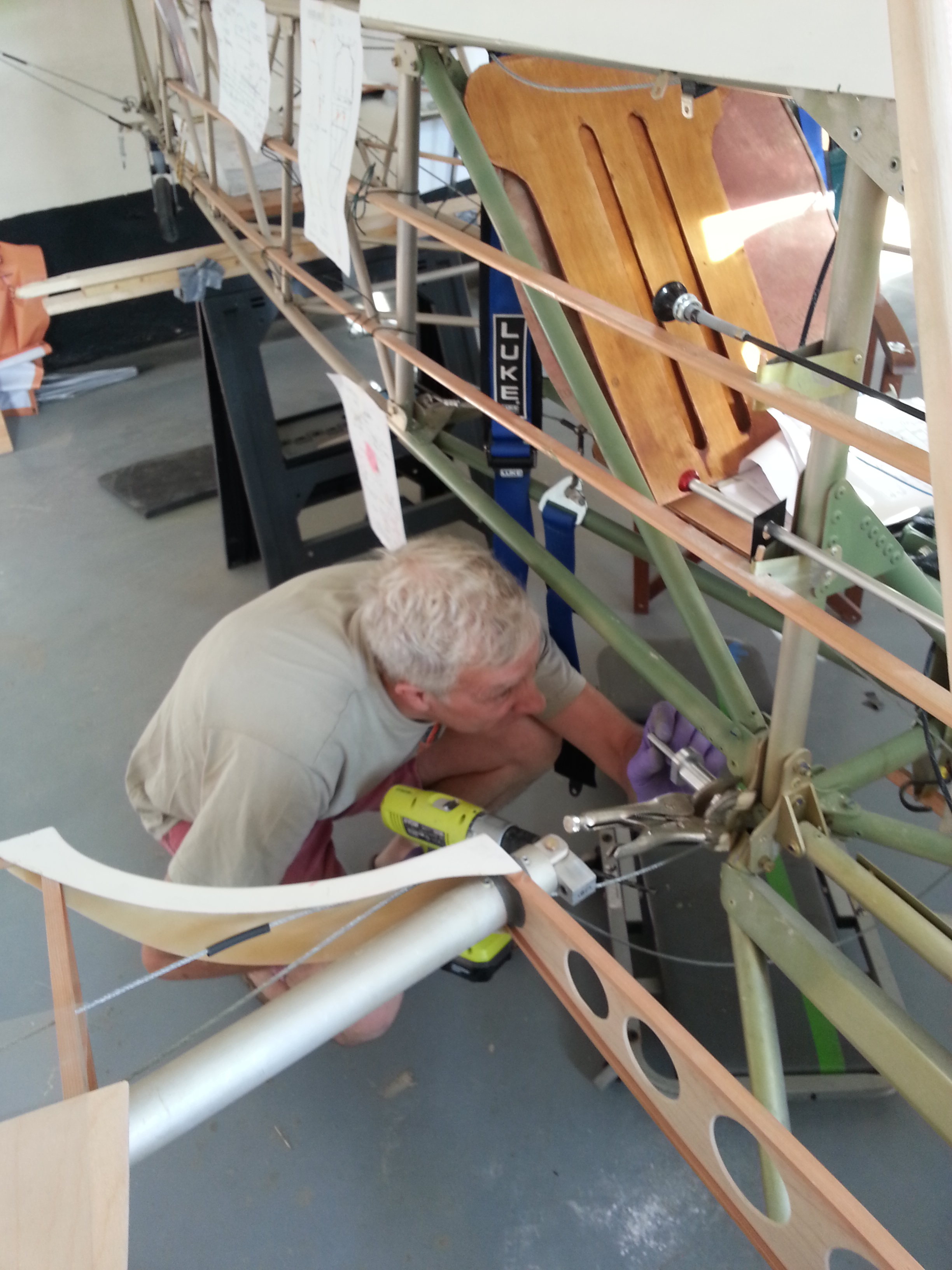
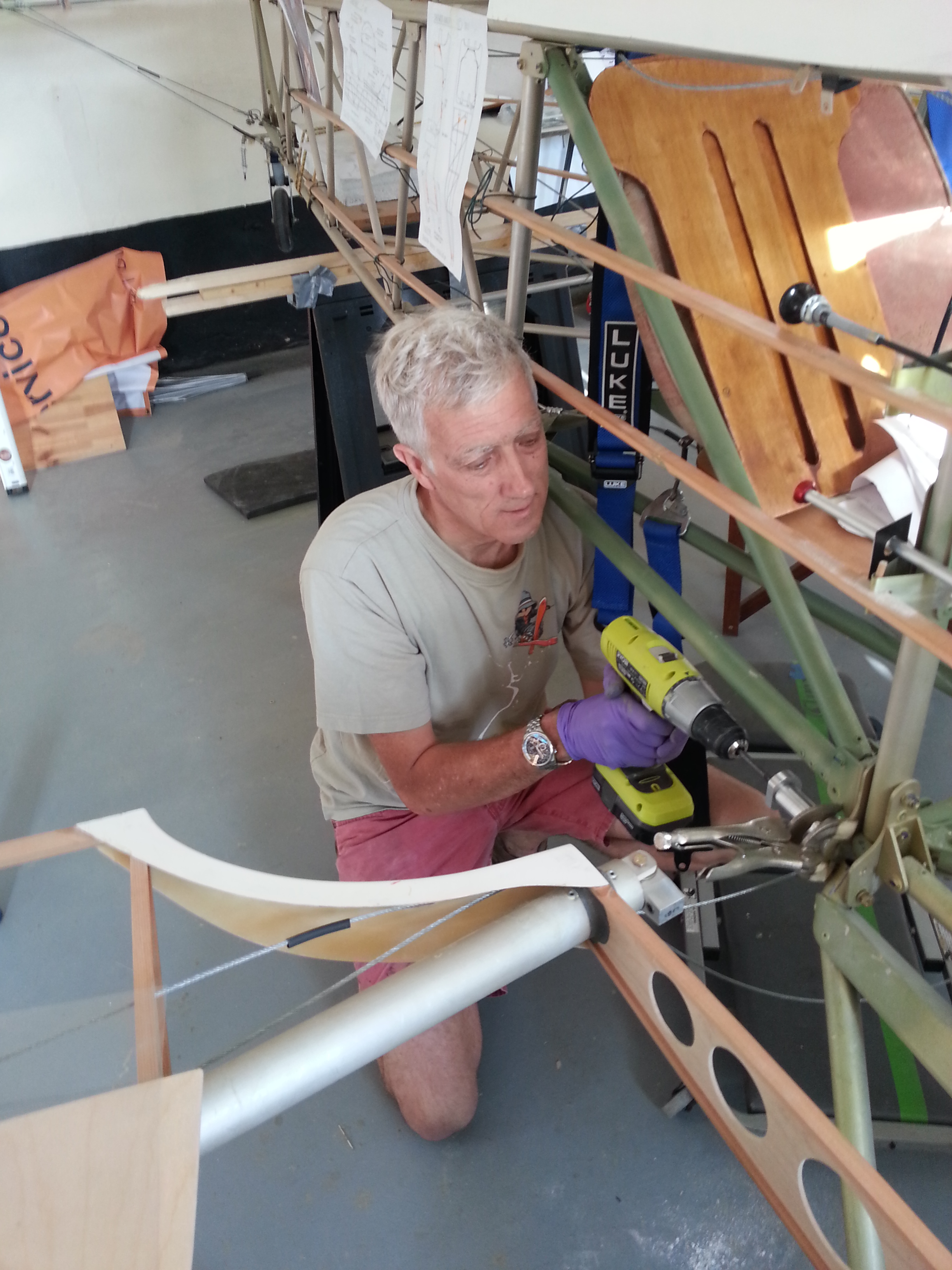
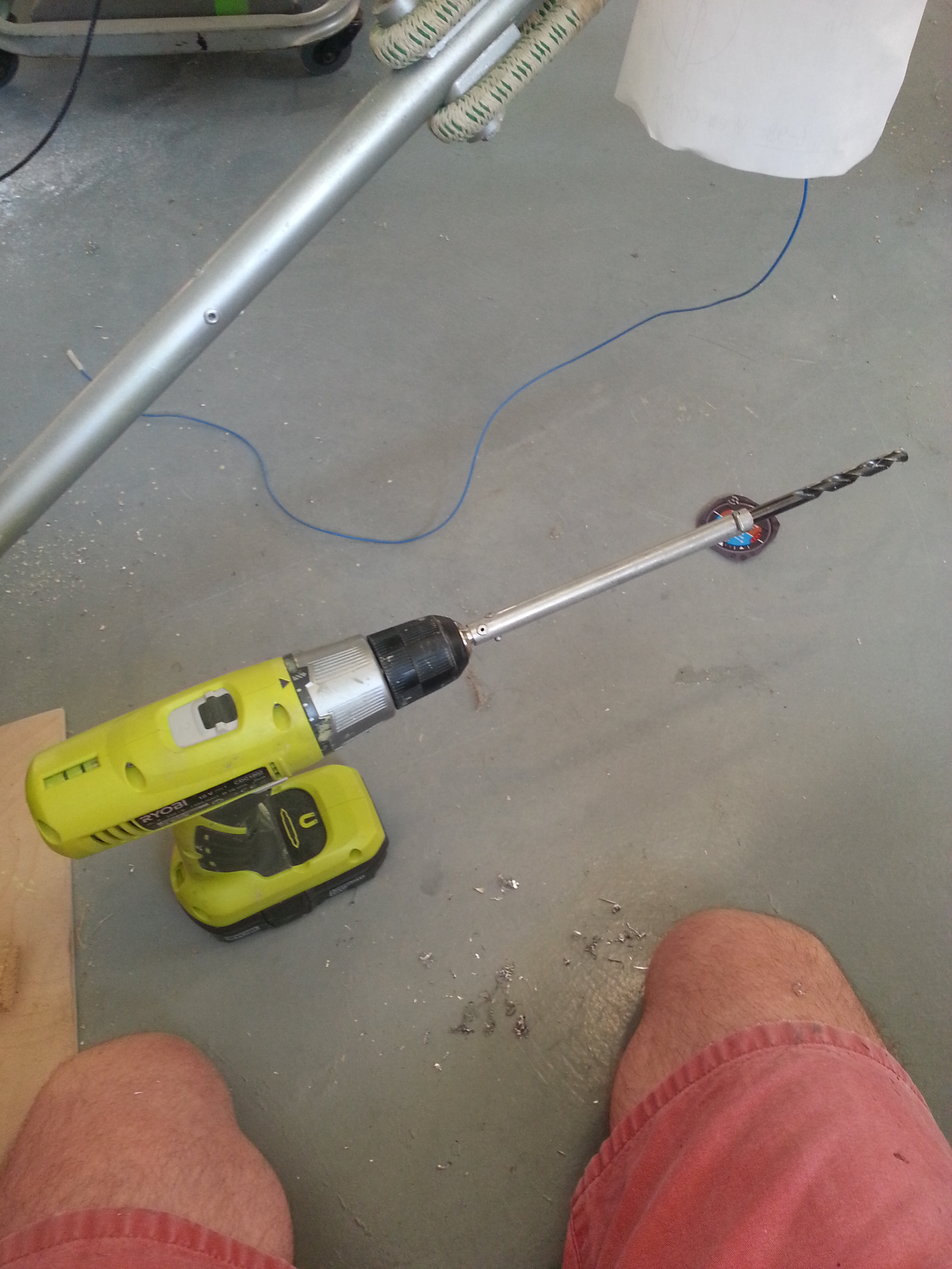
FIG 6 – Get settled comfortably and support drill square, EVEN pressure, SLOW speed

DO REAR FRAME BRACKETS RIGHT THROUGH

wing drill 4

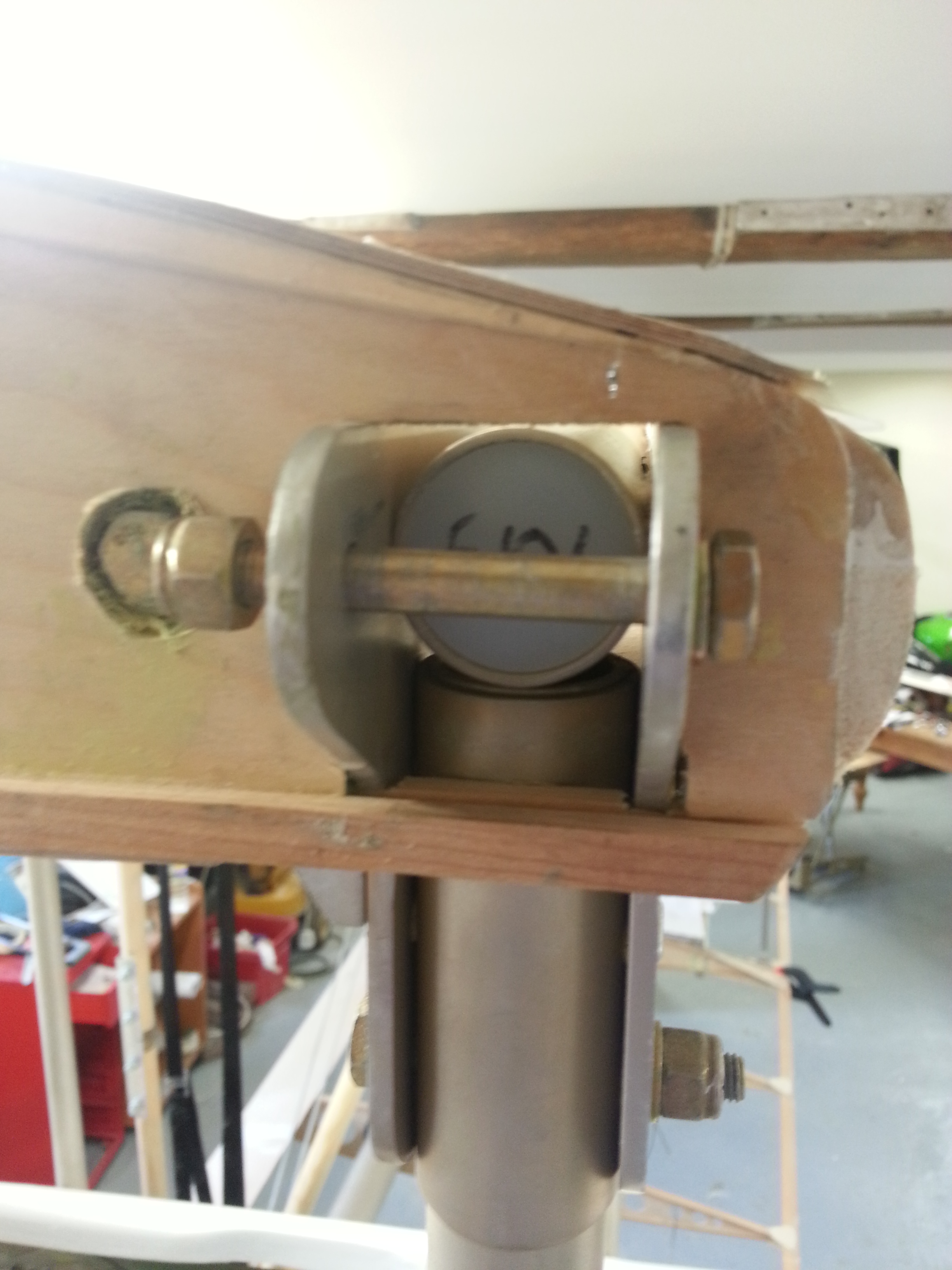
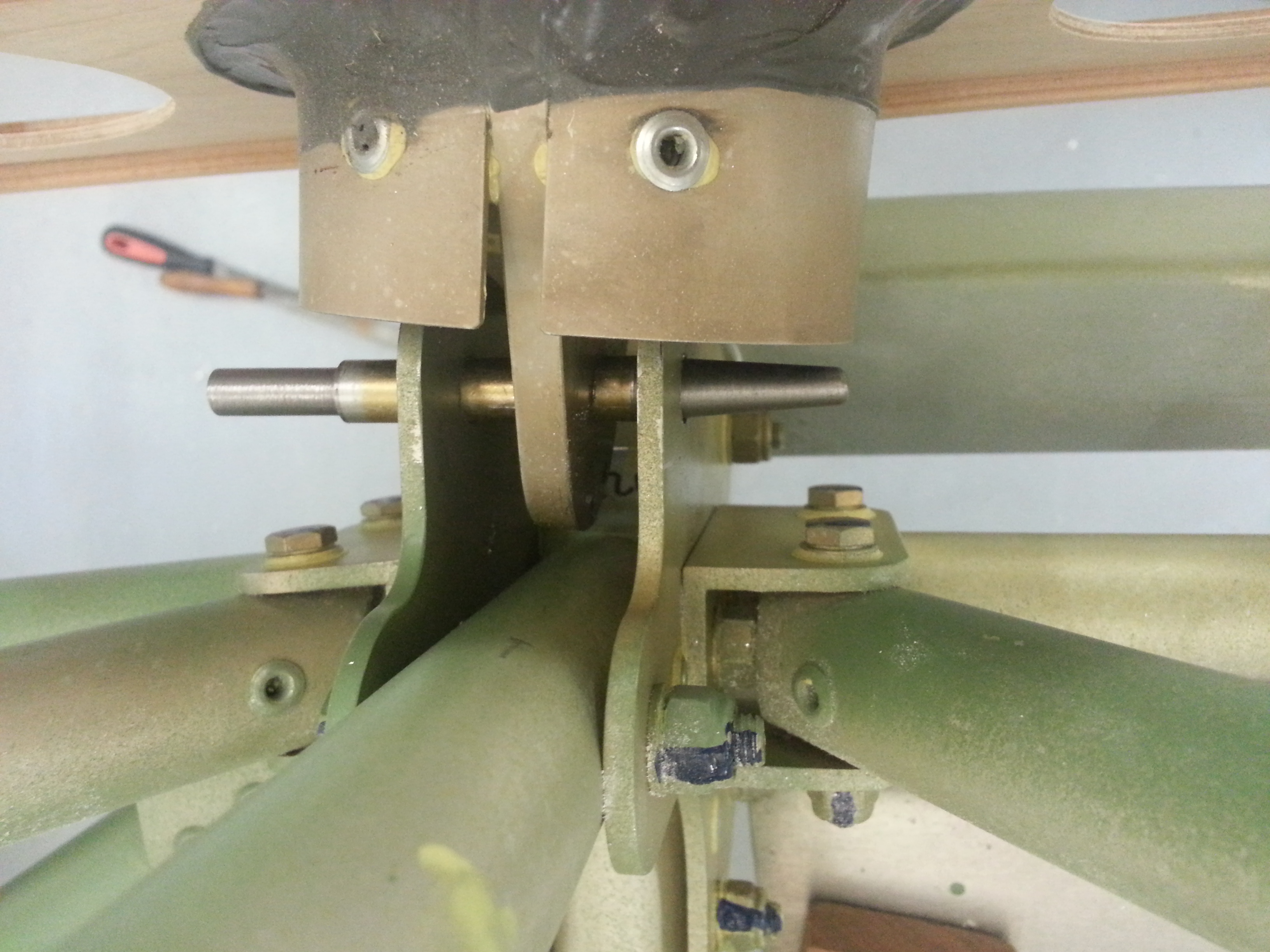
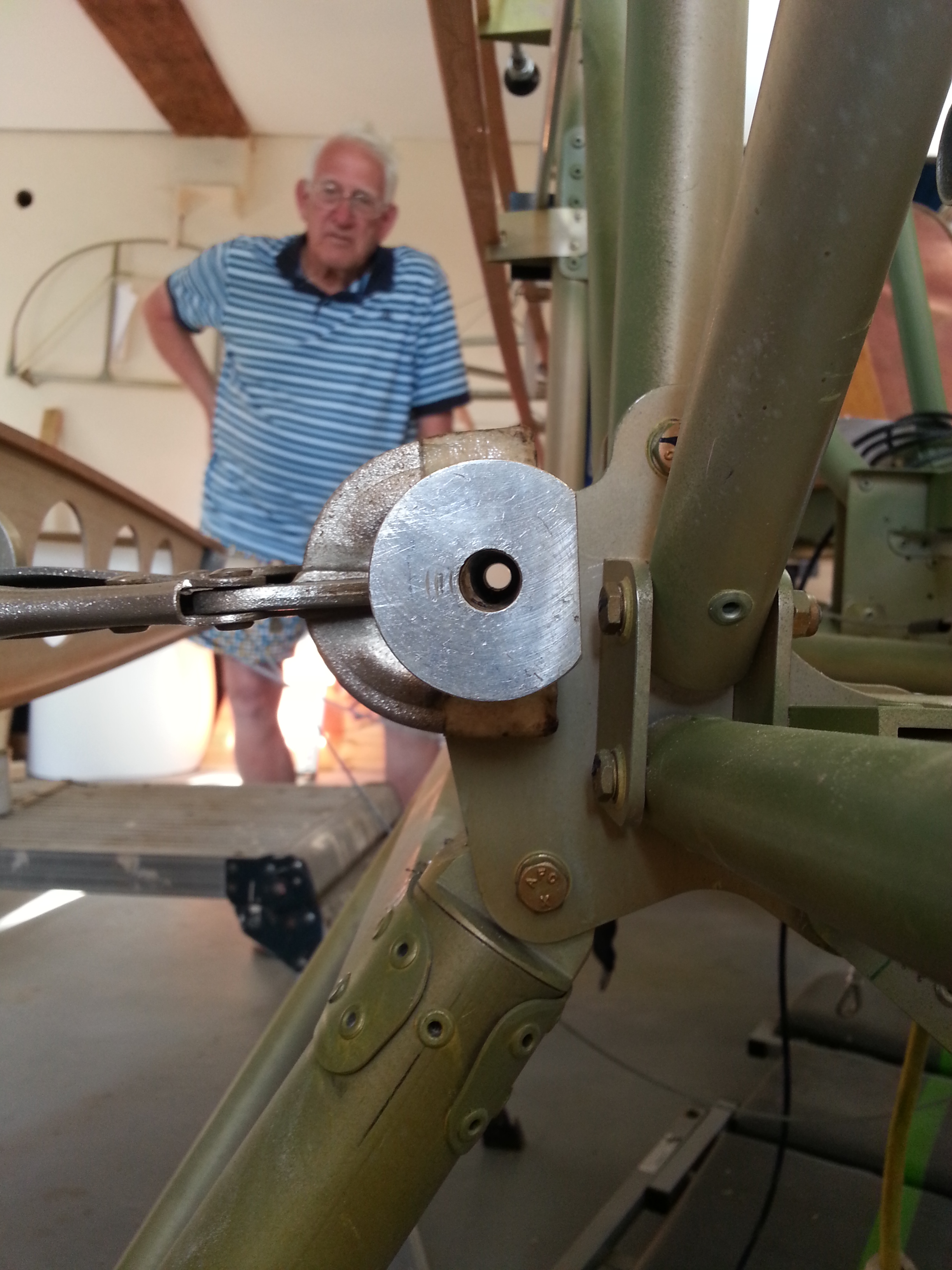
FIG 7: Now clamp the FLAT end on the FRONT Fuselage bracket

SEQUENCE ON FRONT HOLES ONLY (TOP AND BOTTOM)

  1. Align with peg / pin and withdraw
  2. Slide in bushed steel tube
  3. Small drill
  4. Remove tube
  5. Large drill
  6. Reamer – NEVER REVERSE REAMER ALWAYS KEEP IT GOING FORWARD SLOWLY

LOTS OF LUBE AND COOLANT

wing drill 5

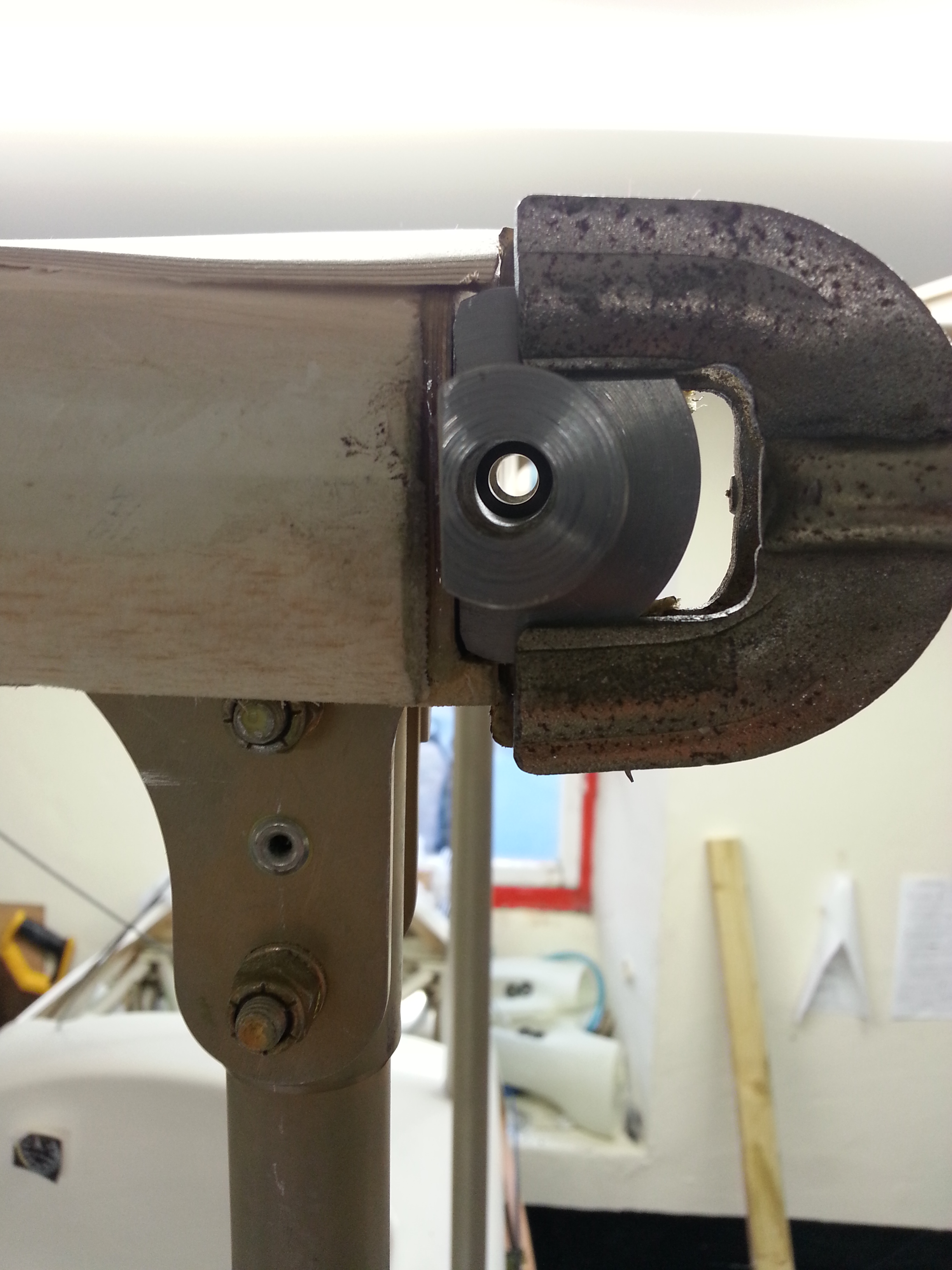
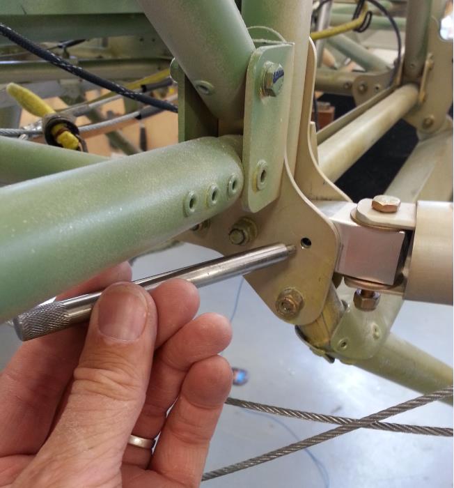
FIG 8: Line of site look through FRONT hole

wing drill 6

FIG 9: If you have used a proper pressure you should have continuous cut on swarfe

wing drill 7

FIG 9: Extended drill bit mount to clear airframe structure

USE the same techniques as above when pre aligning with a central peg and push, withdrawing and then inserting sleeve to accurately guide ¼” drill bit


ALL DRILLING SLOWLY AND LUBE EXTENSIVELY

wing drill 8

FIG 10: Reamer leaves pin very tight – expected

Note reamer is tapered for half of its length to provide a tight close fit


Blog at WordPress.com.

Up ↑