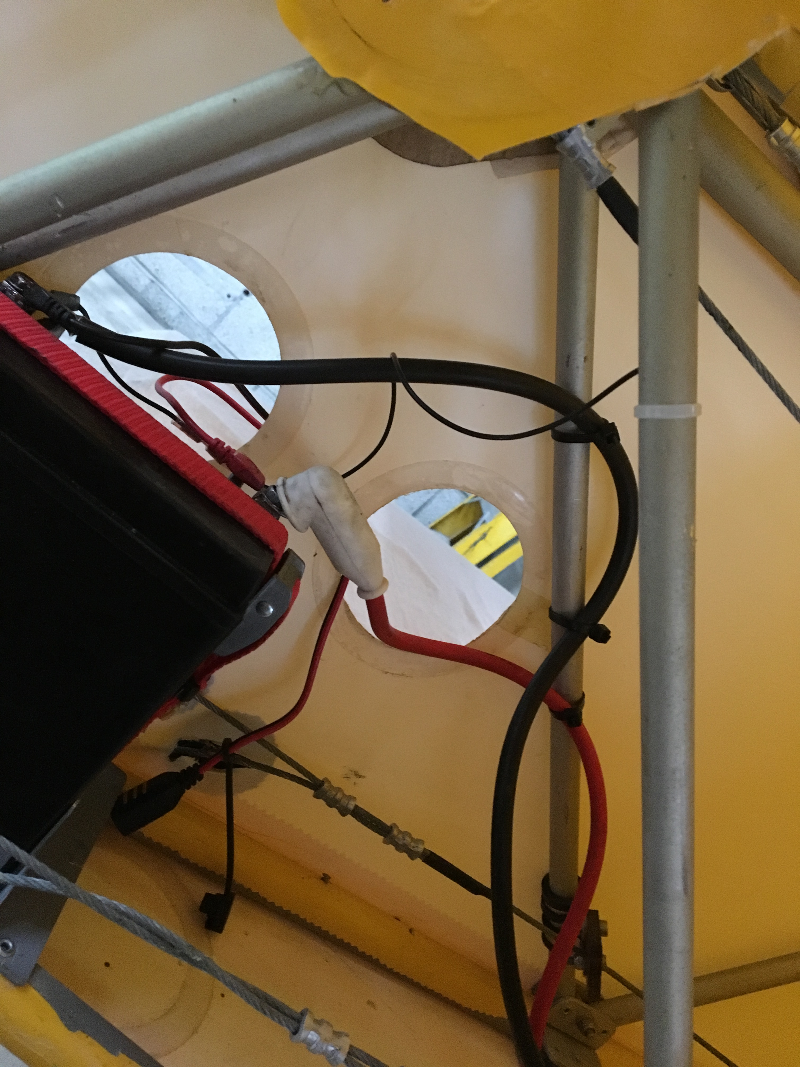
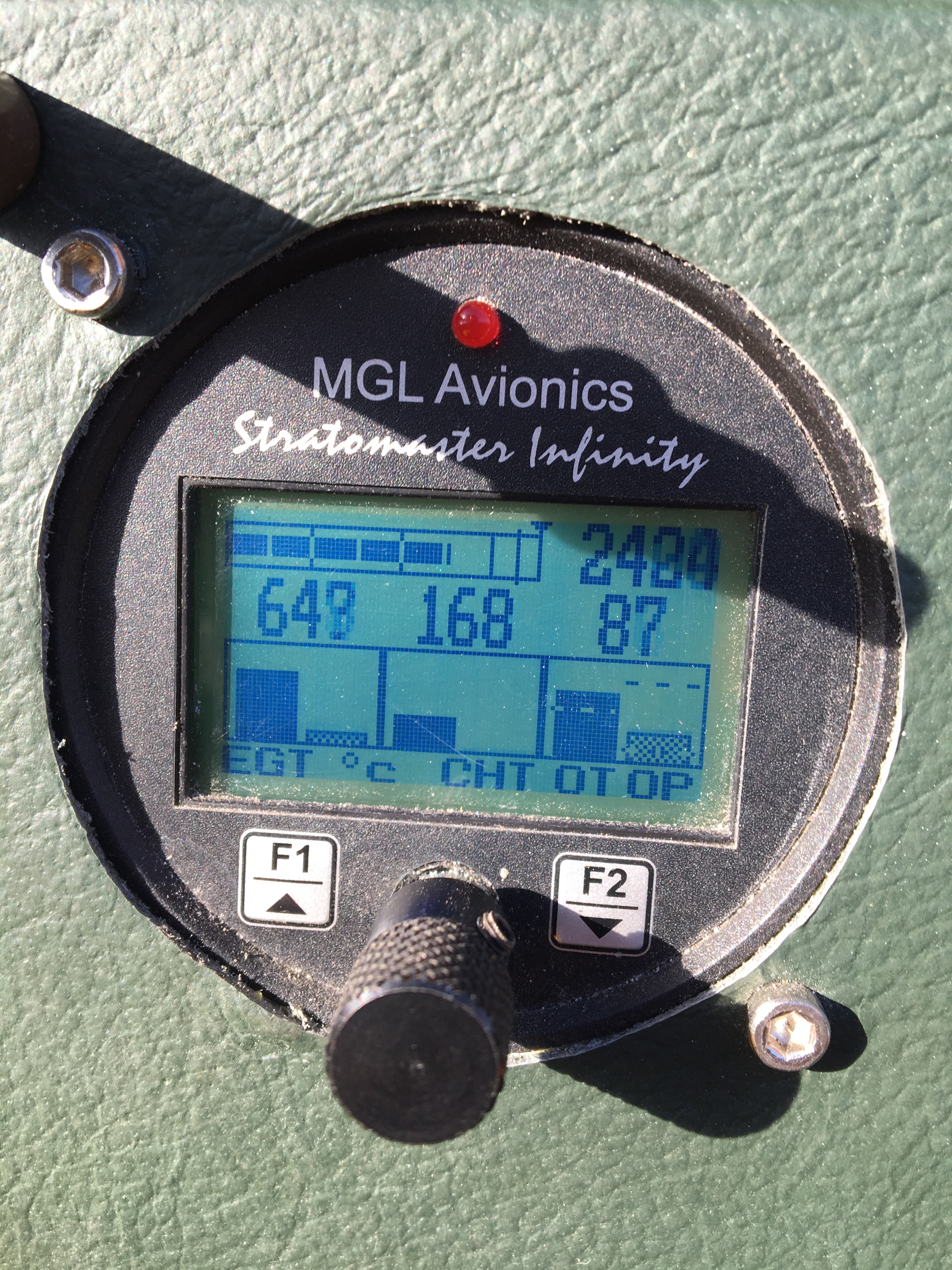
I lost the RPM signal a couple of flights ago and have been going through and through the wiring trying to locate what might have come loose or what continuity might have been lost but nothing seems obviously wrong !
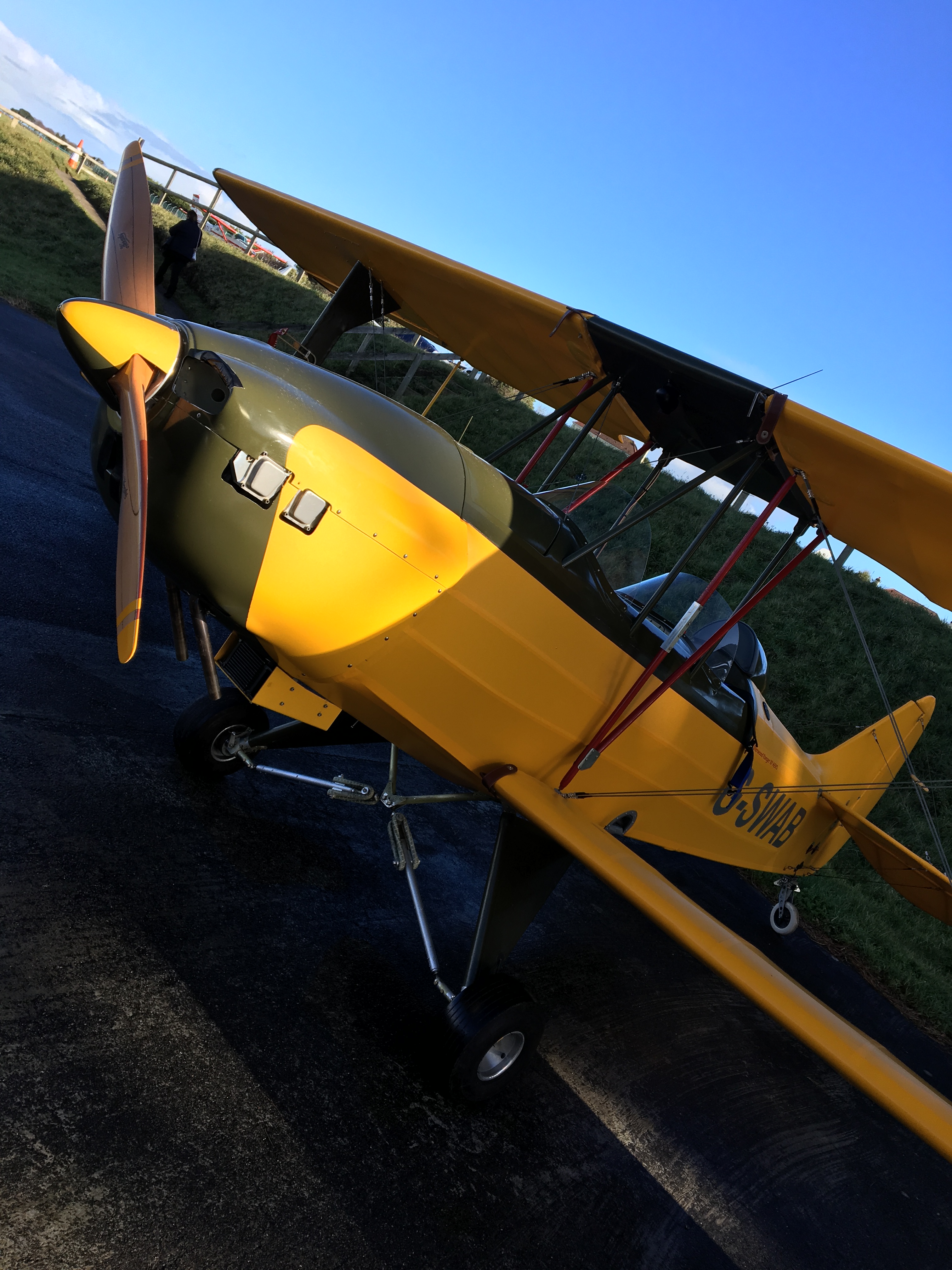
I then went to test fly on Sunday and got as far as the threshold and then my Trig radio flashed up a very small warning saying ‘Warning – Low Voltage’ …. Now, I didn’t realise the Trig even had this feature but, as we had a very very busy circuit with the local spot landing competition in full flow – I though the last thing they want is me having a radio failure in the circuit … so abandoned the planned flight and went back to the hanger to investigate further.
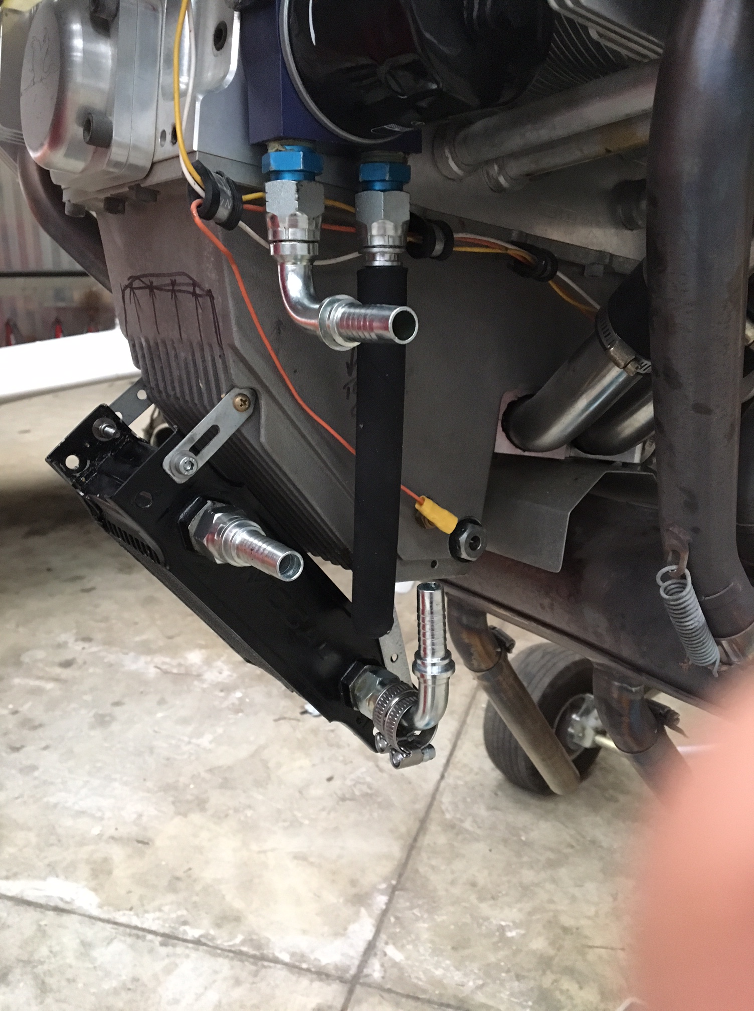
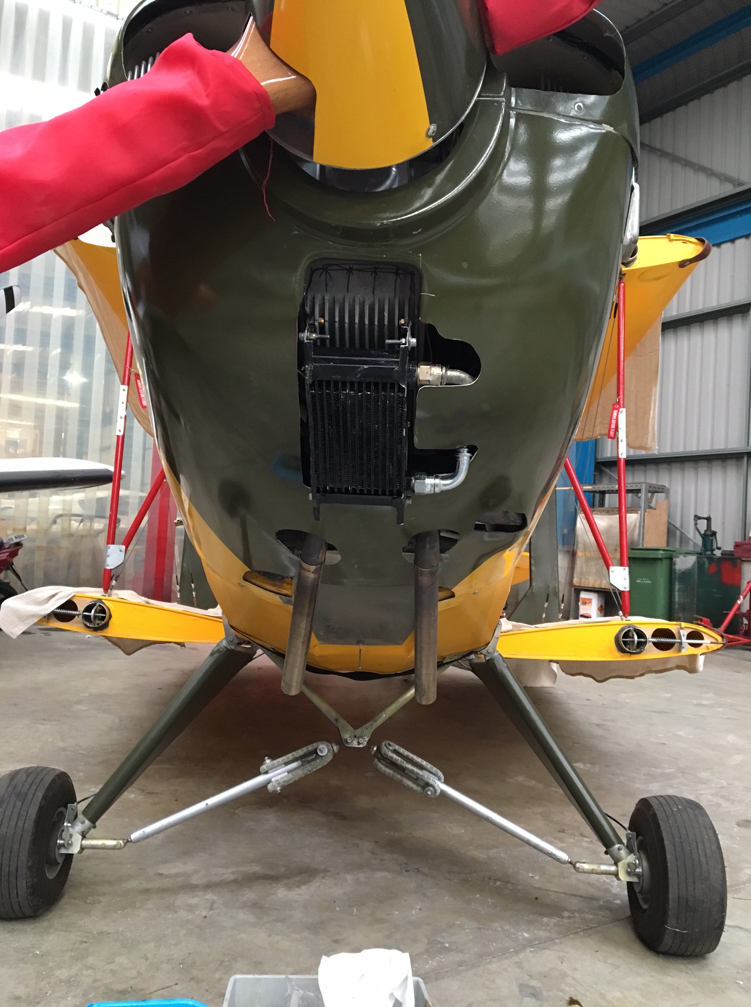
On putting the rear battery on charge it sure did indicate it was down .. so then put 2 and 2 together and suspected that a failure in the RPM readout (which splits from the regulator feed) and no charge could only be the regulator …
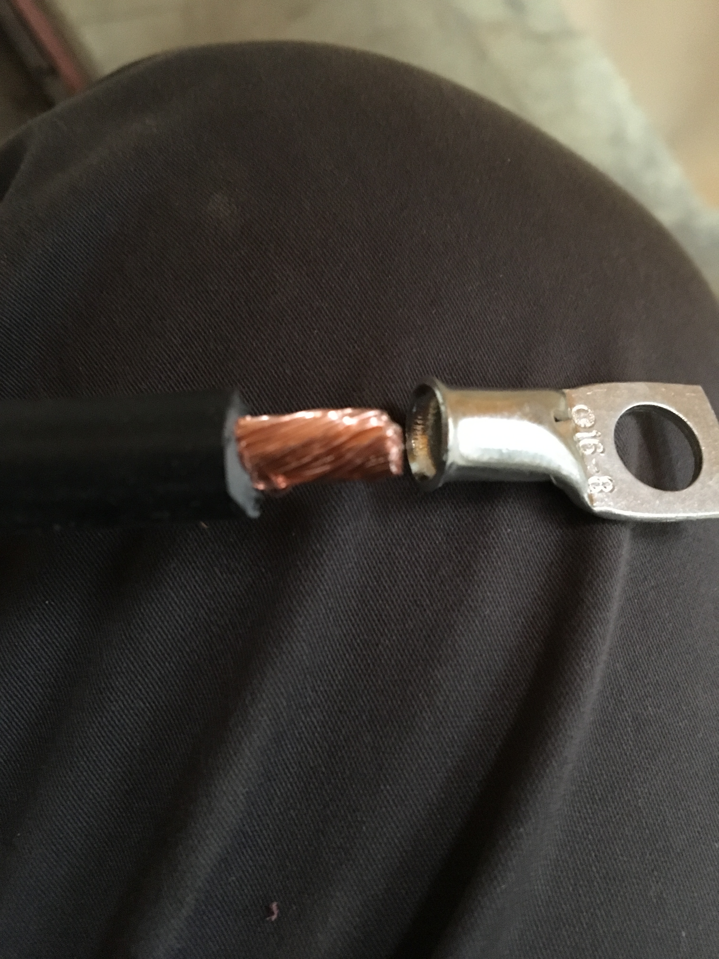
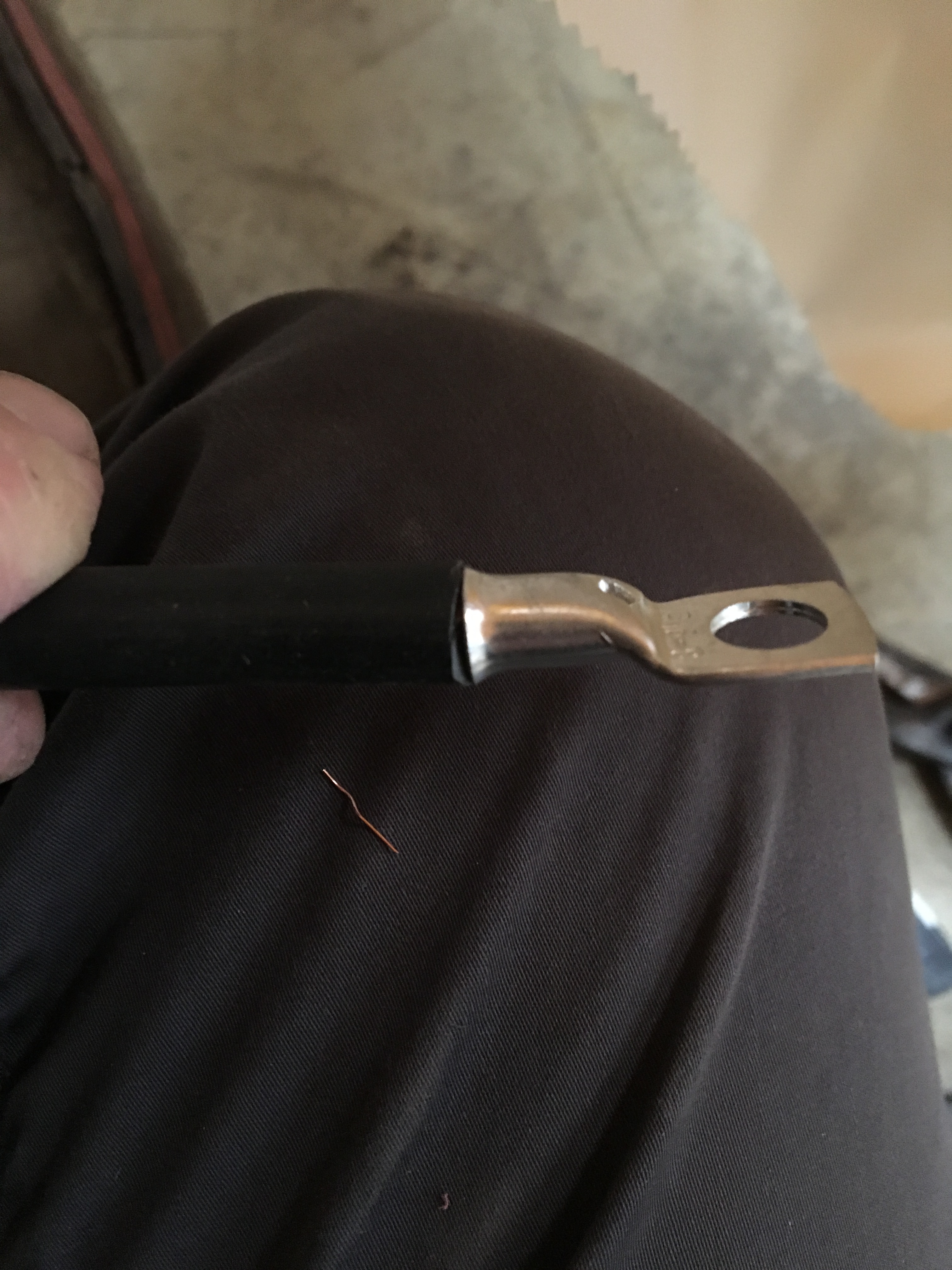
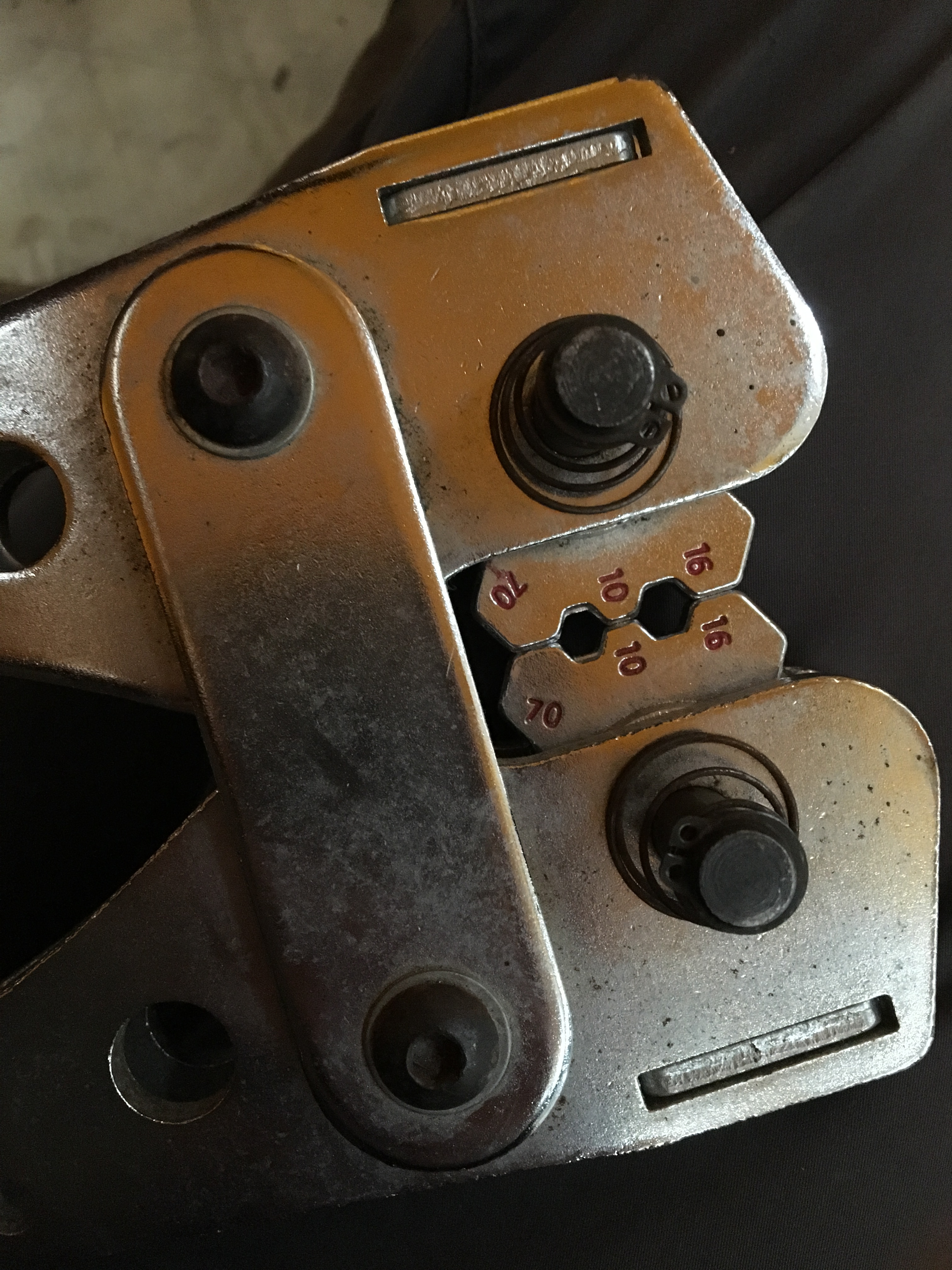
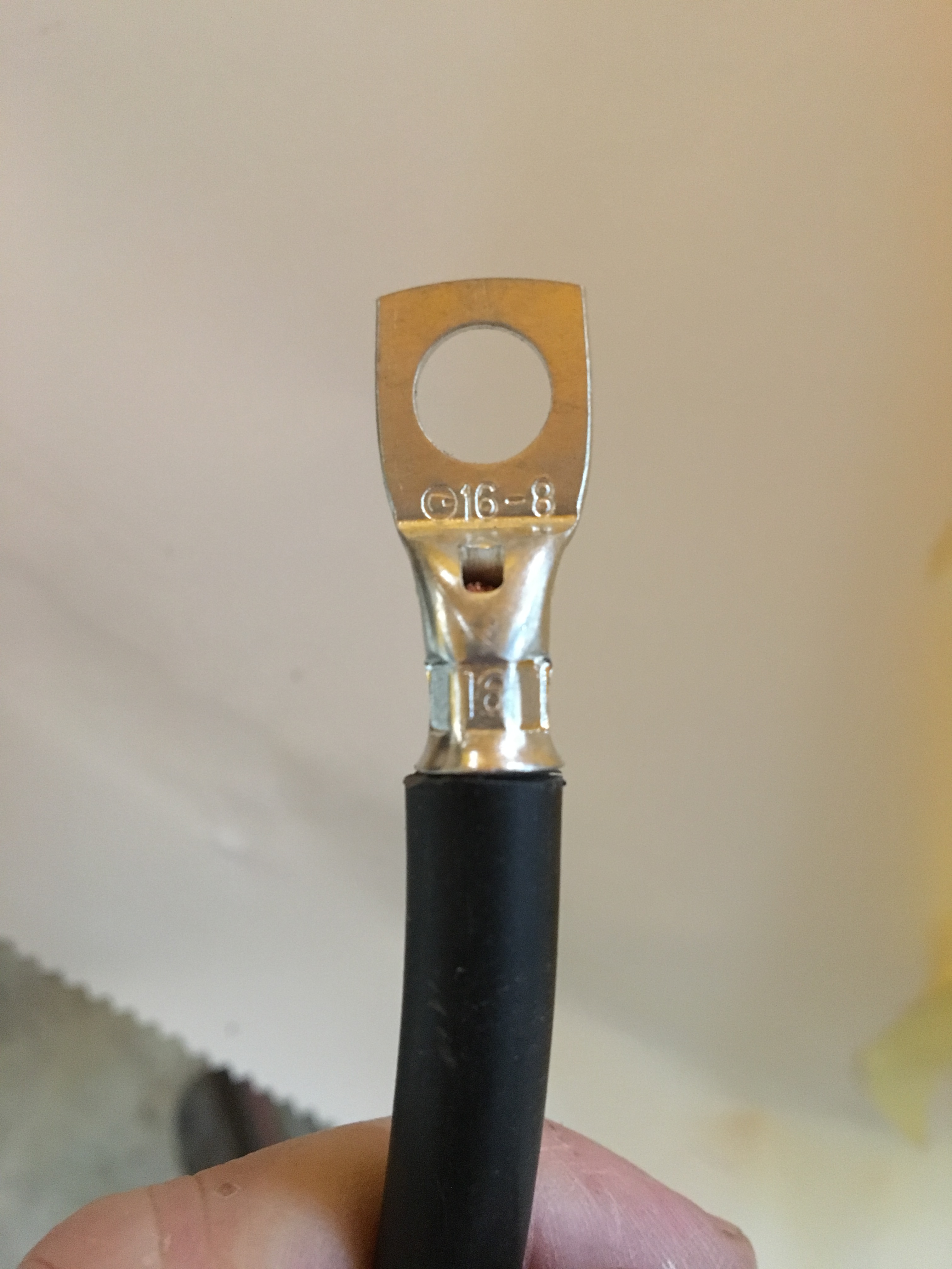
Changed it to the spare I had – took about an hour as the lead adaptors in my wiring harness I had made to be handshake connectors for ease of removal .. the new one was car bullet type connectors.
Popped it in situ and test ran the engine … BINGO .. nice fat RPM reading and voltage now looks good but will monitor over next few weeks


 plus some in flight testing")