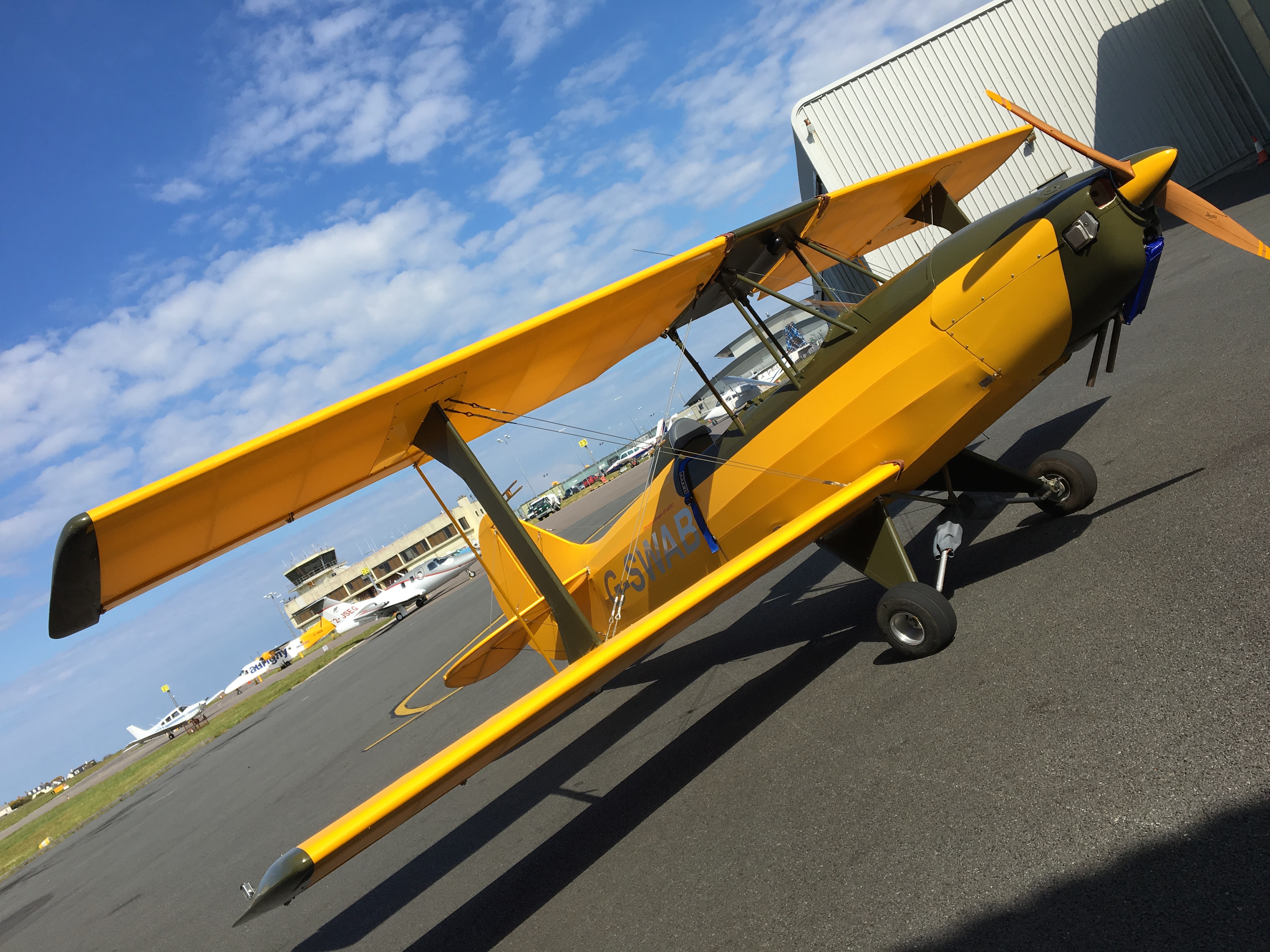
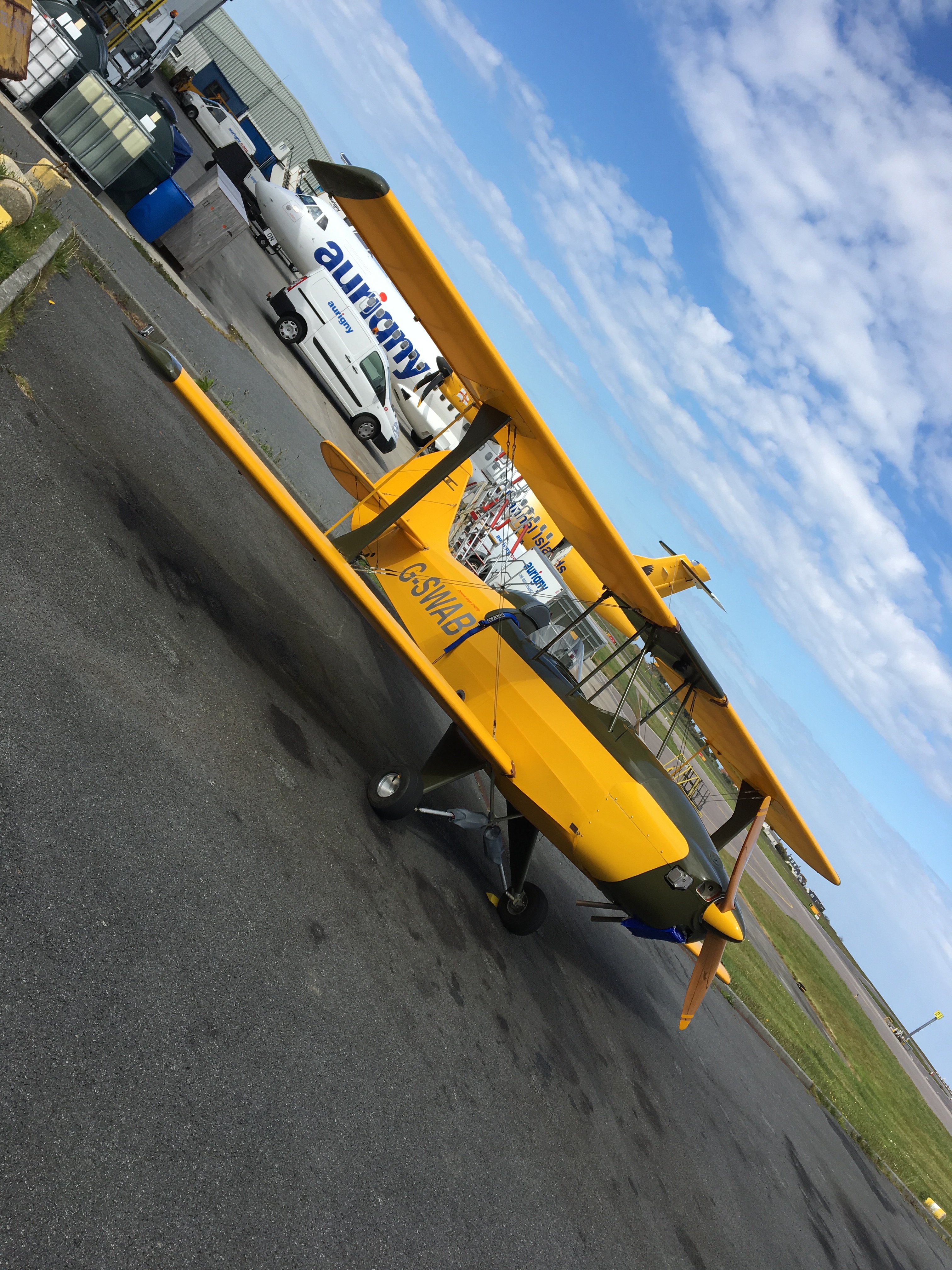
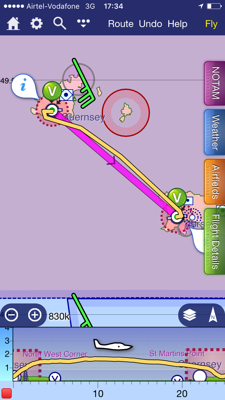
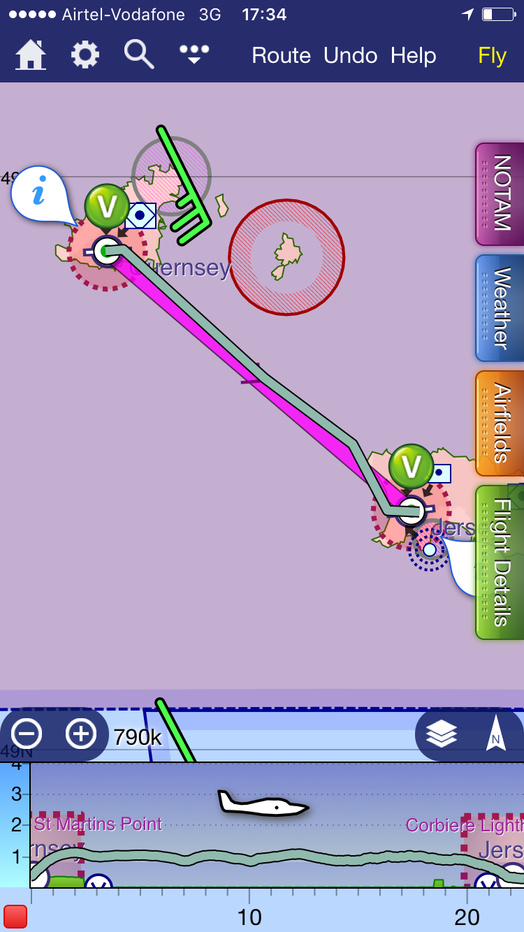
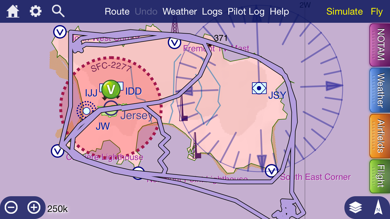
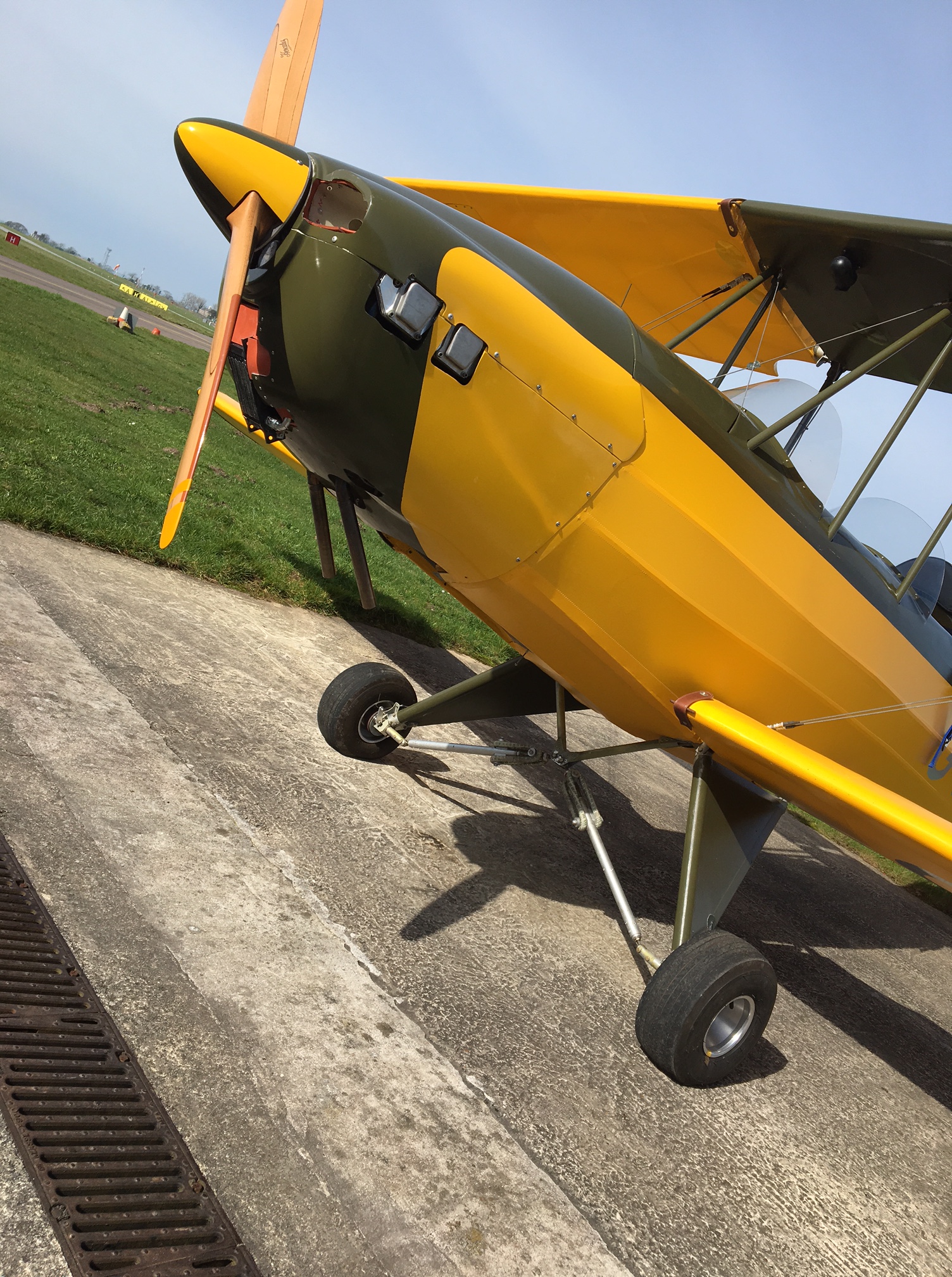
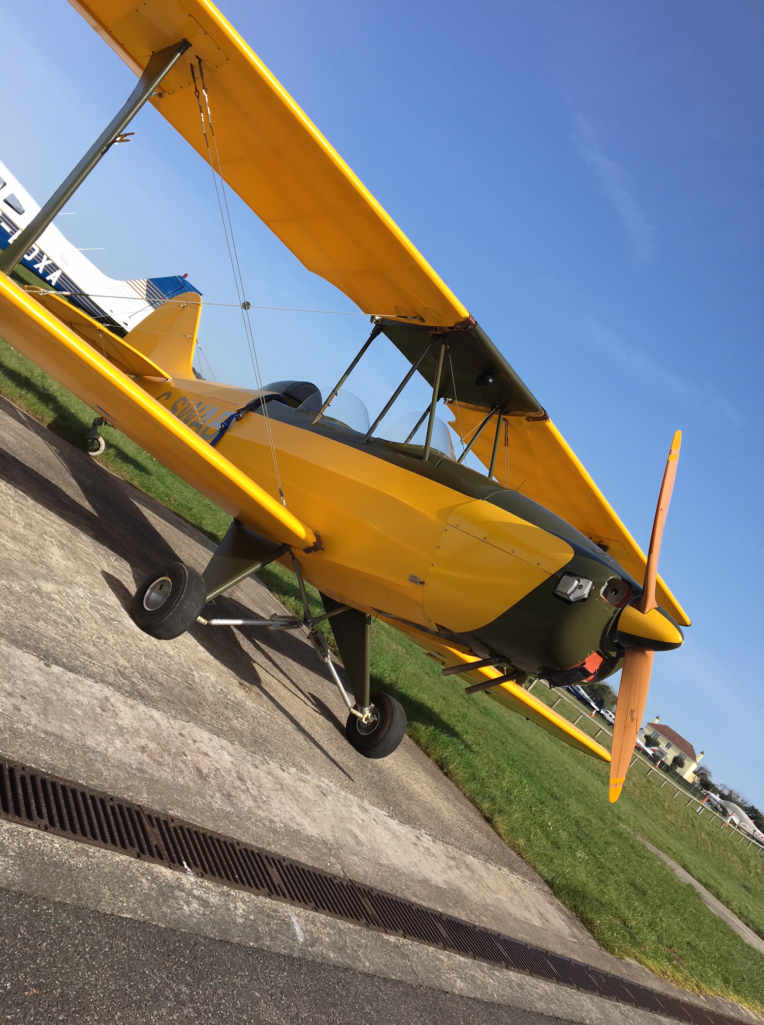
Cooling Update # – March 2017 – No 2 :-) plus some in flight testing

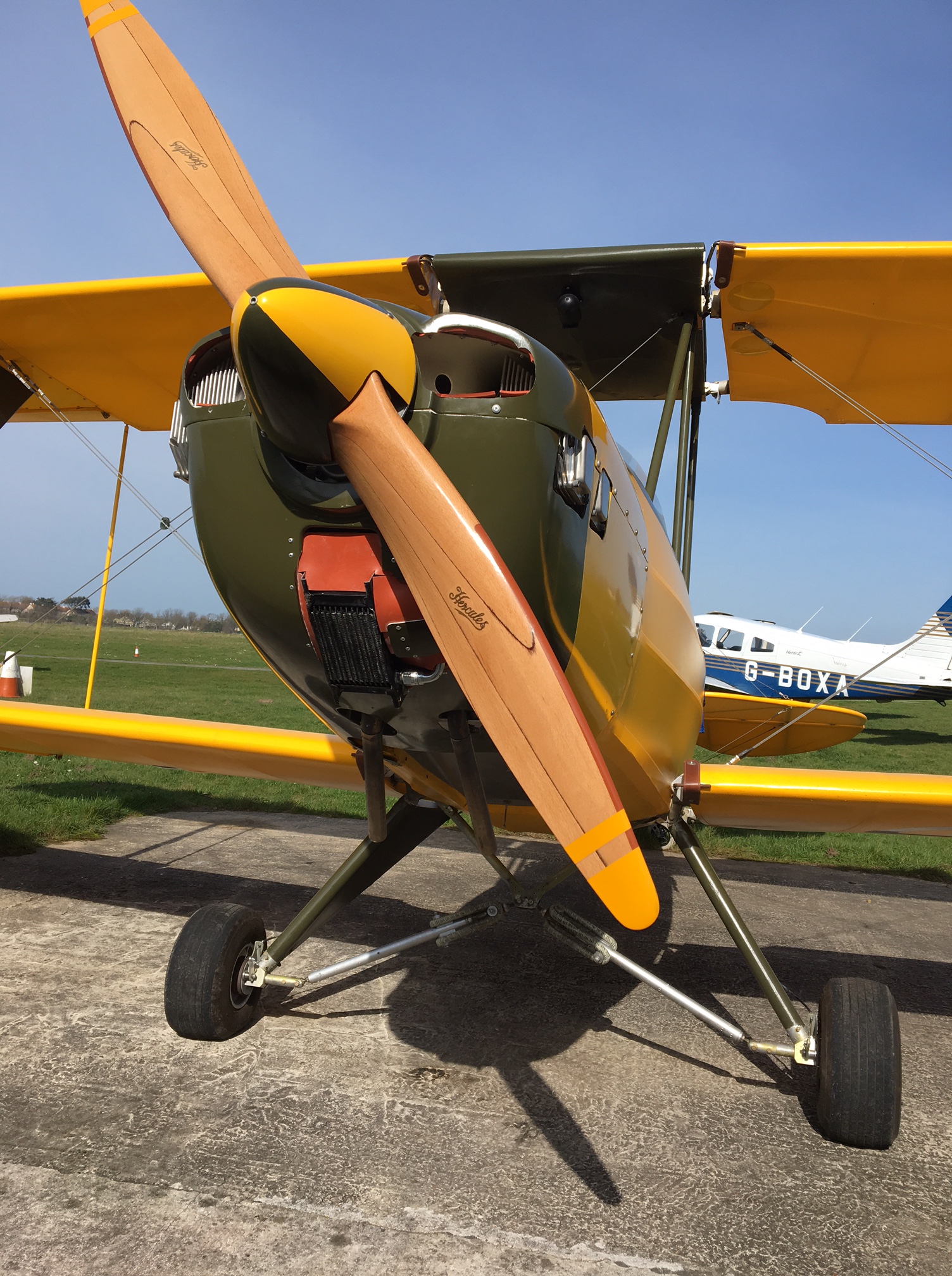
Right … that didn’t work ! still hot

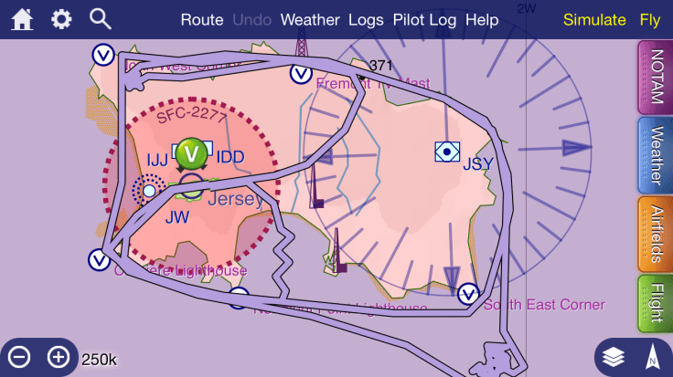
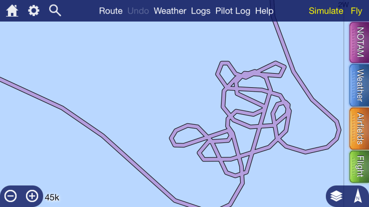
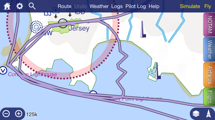
2 more (cross country) circuits were planned but she was up to 115 by the time I got to finals on the first circuit so changed it ‘To Land’ .. getting lots of take off and landings in though ! – always look for the positive πŸ™‚

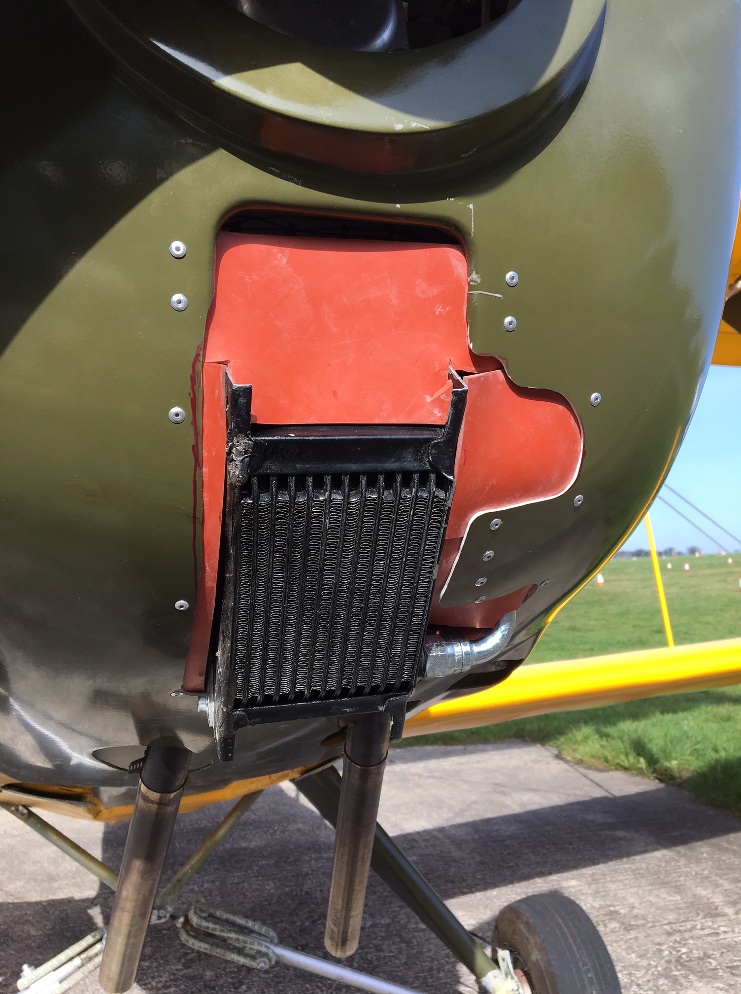
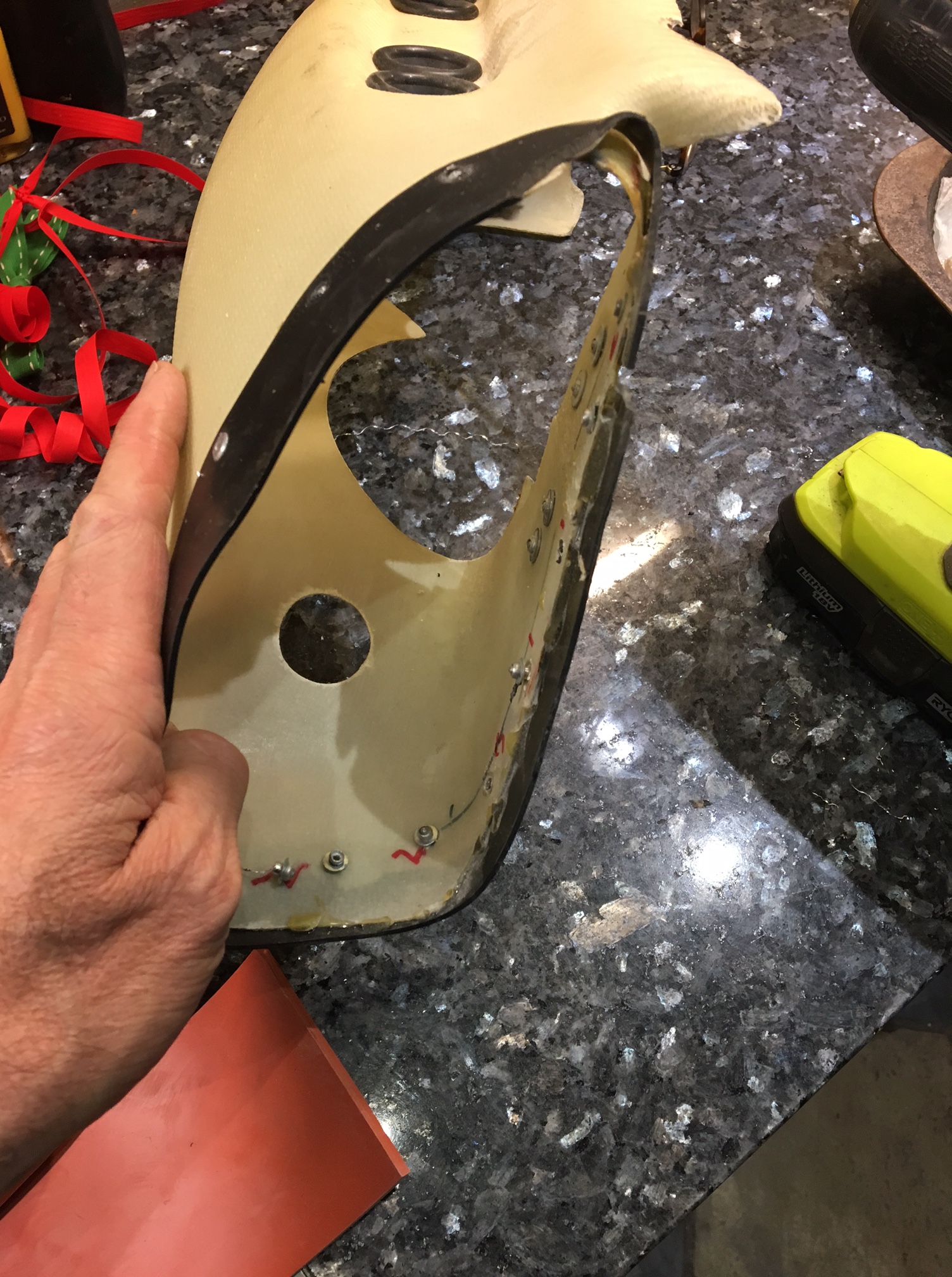
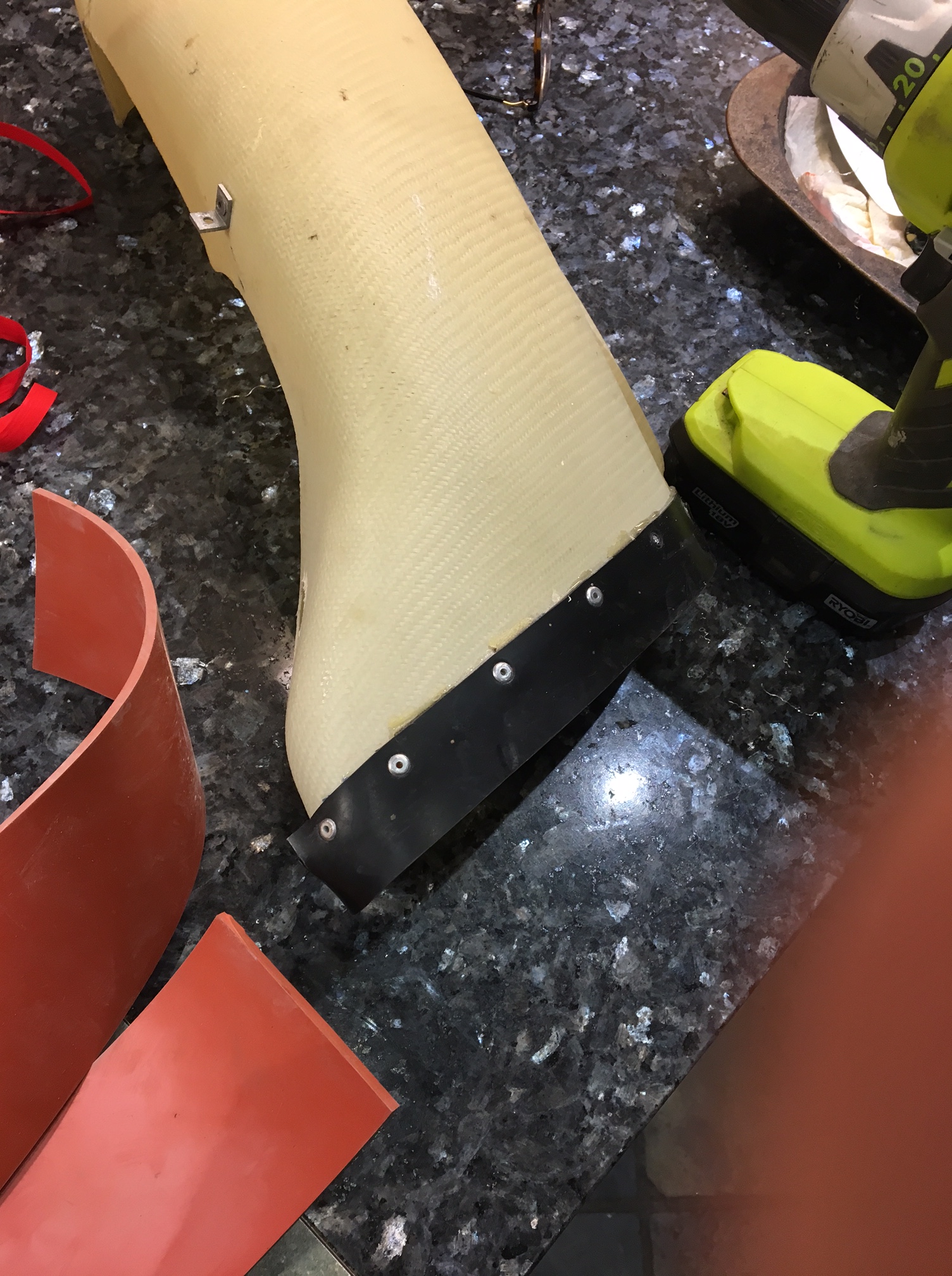
Having seen the other examples I will remove the top duct rubber to allow the air to flow in above the new cooler matrix and then get the whole cowl touched up and repainted once tests prove ok.

Thanks to all for their kind input and advice …. makes it so much better πŸ™‚


One other thing I did on this short test was to start to try the tests that Howard (Barber)Β had suggested … I did a nice wingover on departure into the circuit – which felt great … then downwind I let go of the controls .. fine .. then I pushed full left aileron and let go … just a gentle bob back into S and L ,…. then the same to the right .. such a joy to fly this aircraft ….

So, back on the ground and a hot engine .. 😦

Calls to Paul and Danny ensued over the following 24 hours

Bingo …. with input from Paul and Charles and Rool

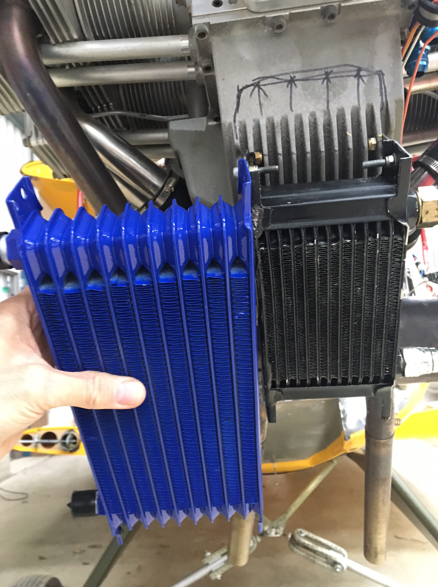
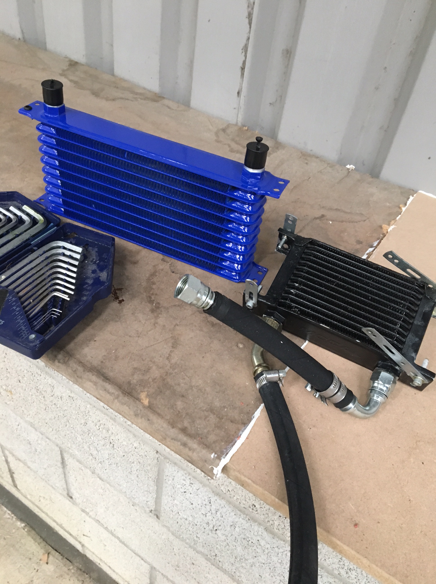
Looks like the cooler i’m using is hopelessly undersized ! – Now I’ve thought back and this didn’t get delivered with the engine … I remember simply measuring the gap of where I planned to locate it .. ie the scoop under the belly and then buying one to fit. Not very scientific but I’m not sure I have seen a spec for a ‘standard’ size in the Jab manual.

It turns out that Danny and others have one that is around 300mm x 140mm x 40mm

Mine is 140mm x 90mm x 50mm – so probably about 25% the size of Danny’s !!

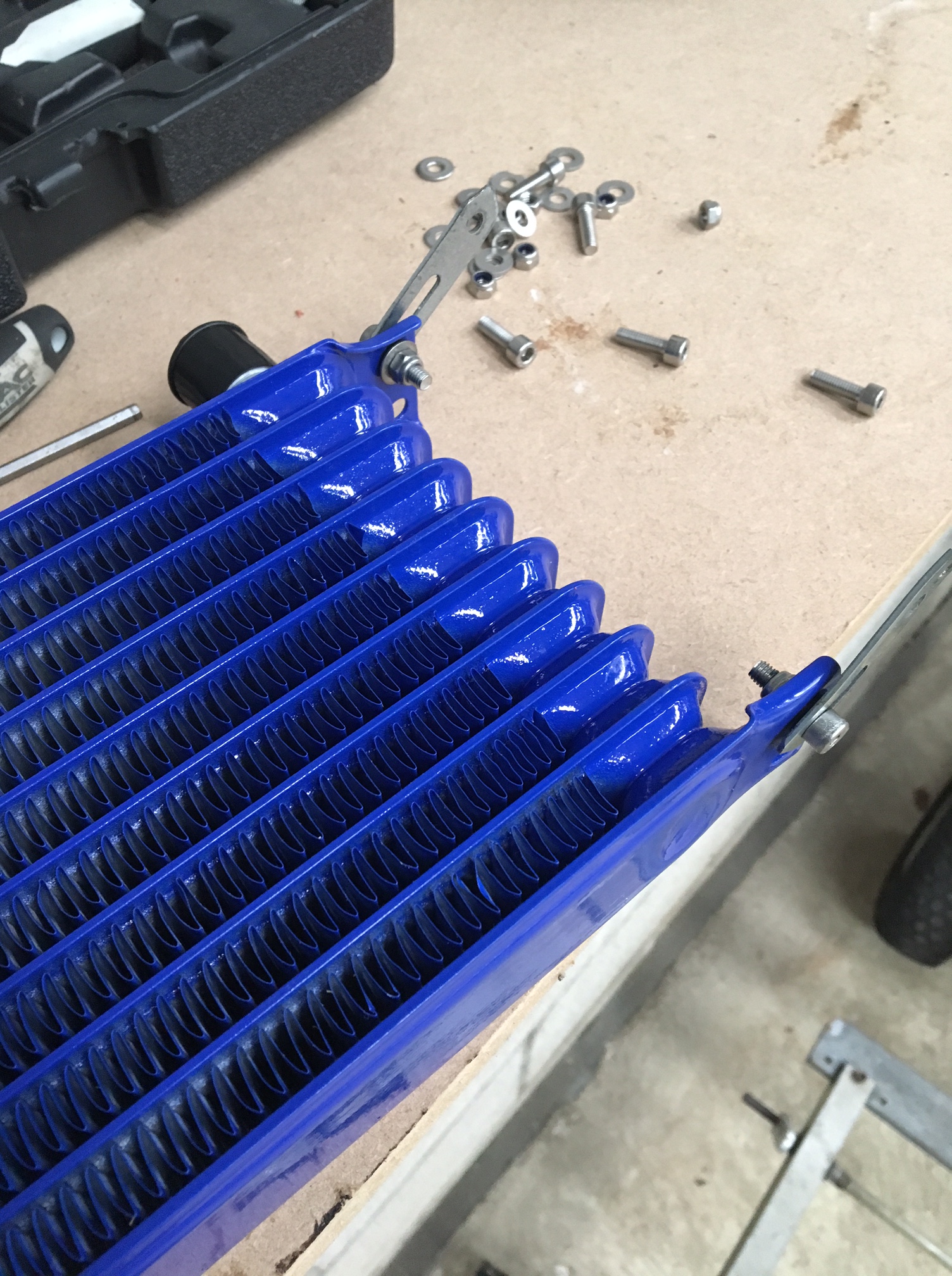
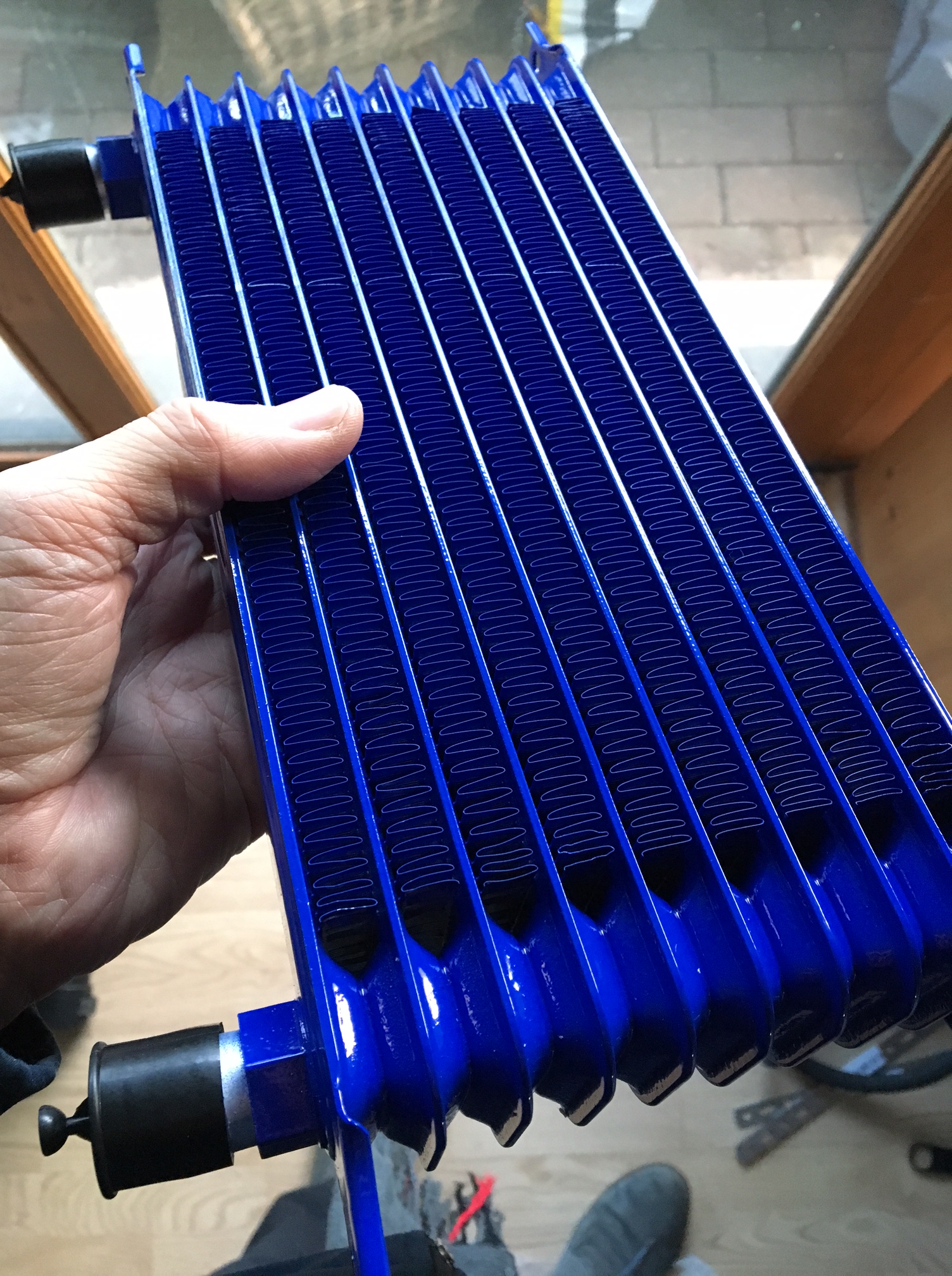
Danny kindly dug out his spec order number and I am now awaiting the shipping to Jersey – hopefully 48 hours

Rool had a neat idea of making a front shroud for the cooler .. protects and also acts as a gurney to create backdraft and suck the air out … so have a sheet of nice aero metal (thanks Graham CIAS) and that will go on after the next test.


Cooling update No # – March 2017

Well … this has proved to be quite a challenge as the art of cooling – without the aid of a Β£1m plus wind tunnel makes it a little trial and error … perhaps Benjamin could sneak a mornings use of the Williams F1 tunnel and that nice long smoke pipe that would really let me know what the airflow was doing πŸ™‚

Anyway … back to chalk and board .. as my first instructor used to say …..

In this case its drawing on experts like Paul HS and Danny B who have been really great through my current challenges and have certainly kept me going with this ‘long distance’ OU style course in aerodynamics.

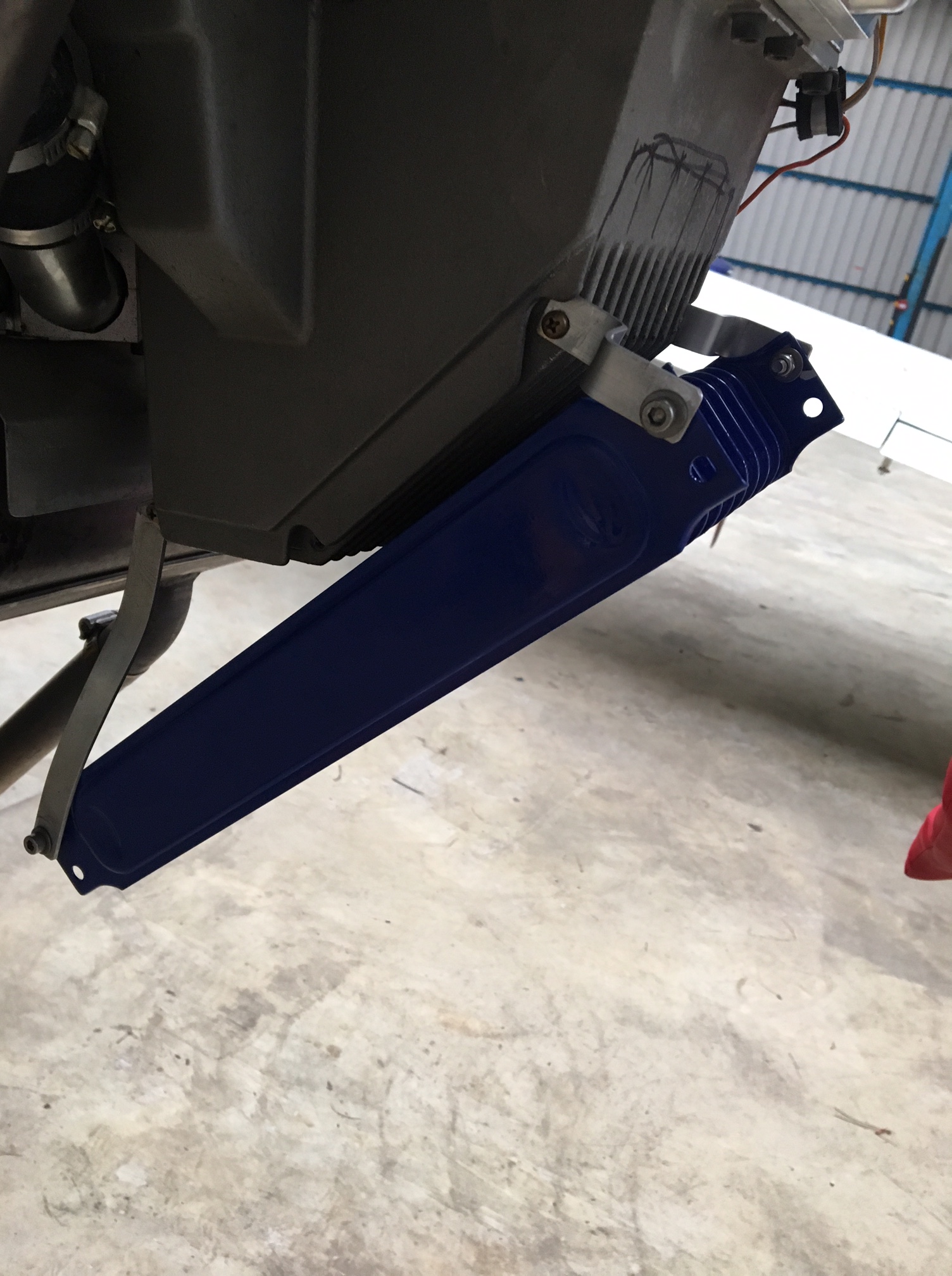
As you can see from the previous blog entry I had failed to shroud the intake area around the oil cooler matrix – Now done … but … 2 Jersey style circuits (around 6 miles !! – EACH ! ) and it proved to not fix the problem and temps still crept up above 100.

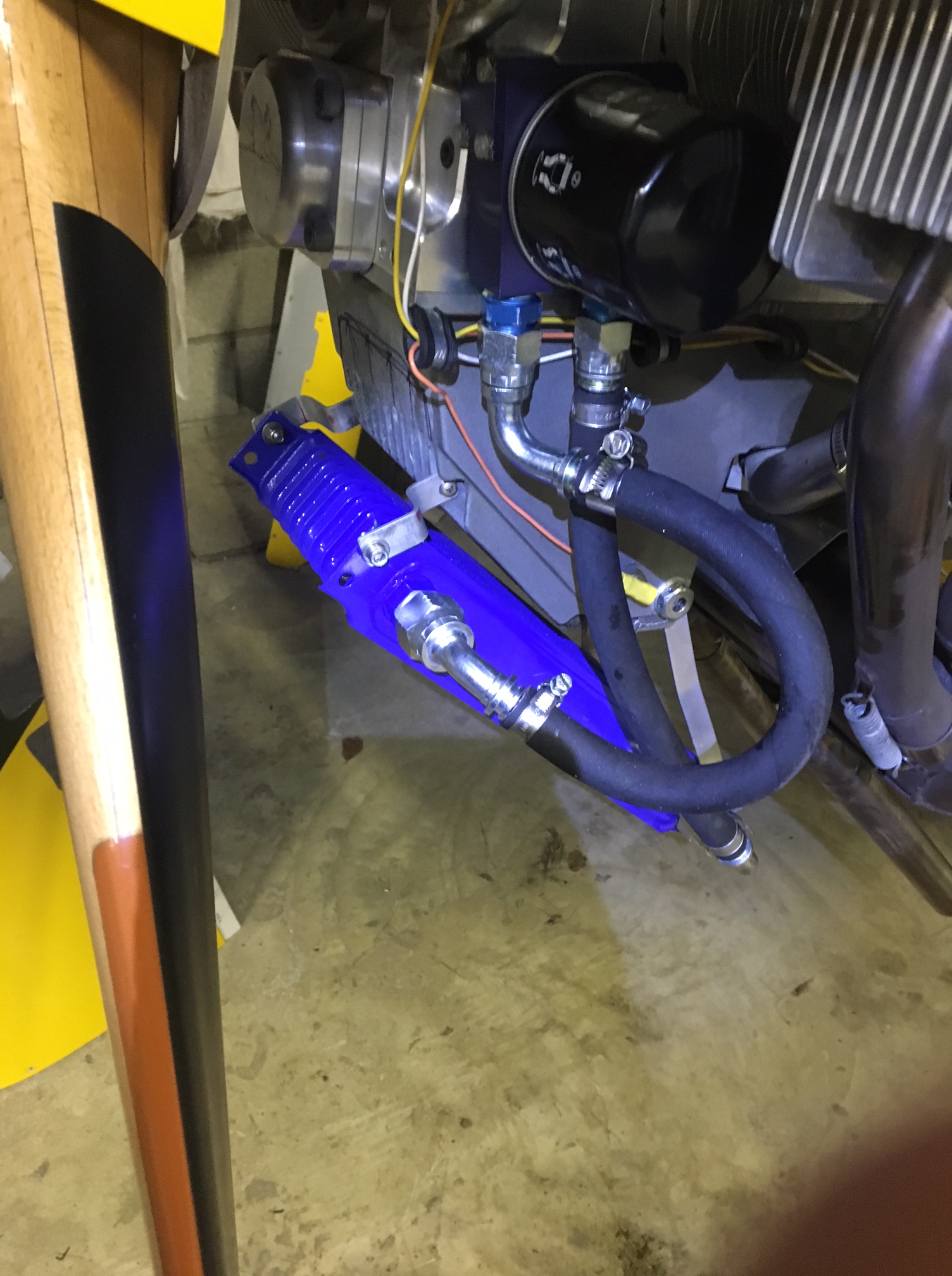
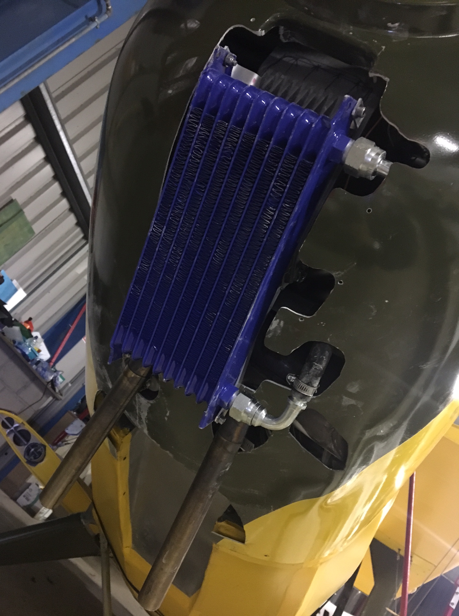
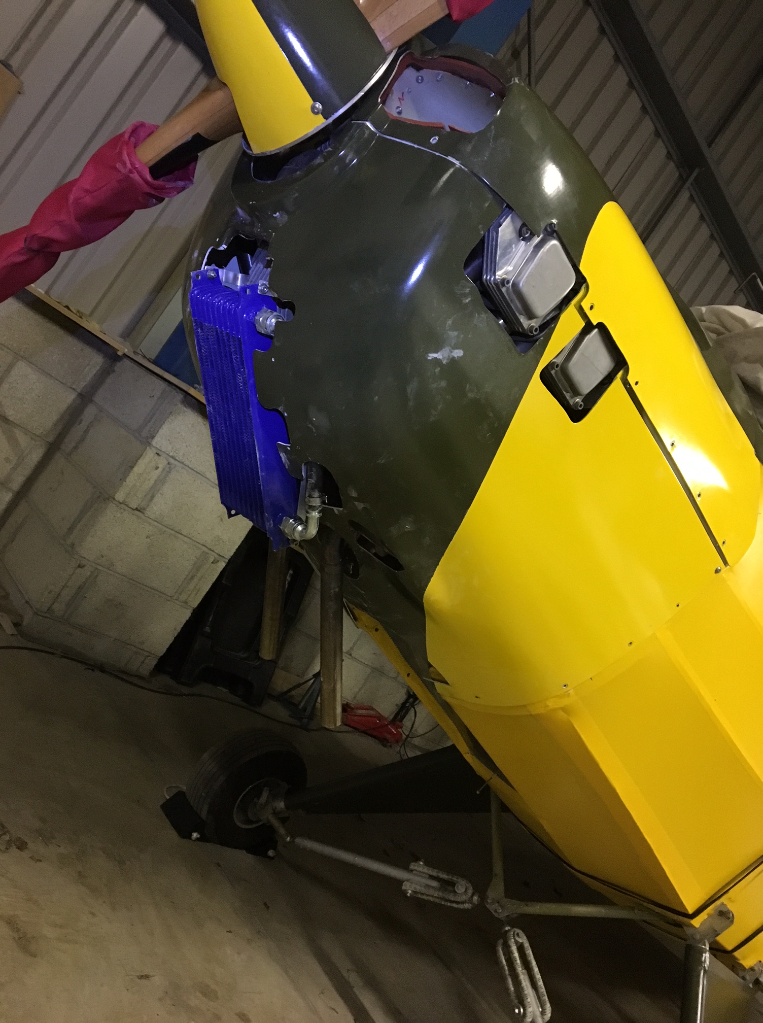
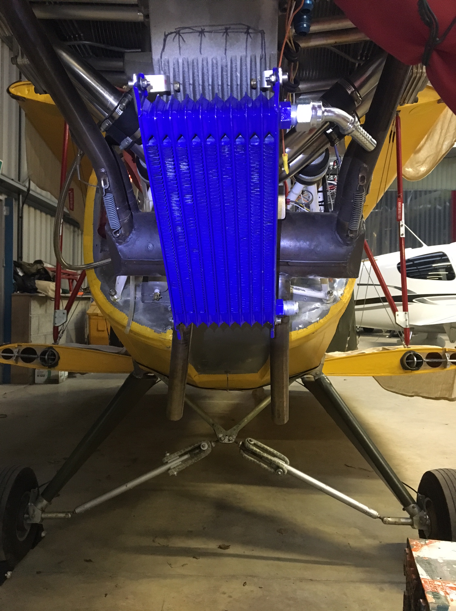
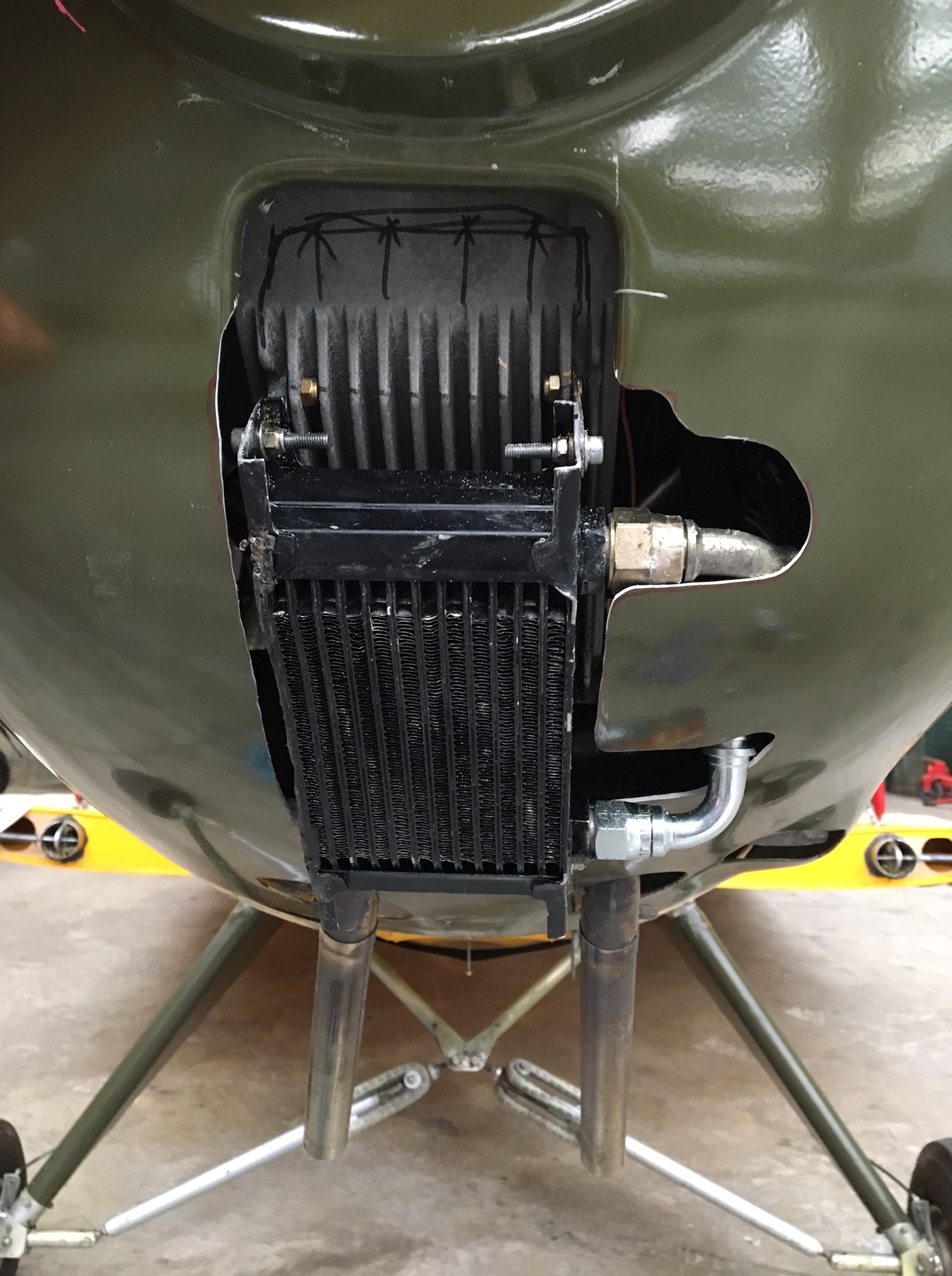
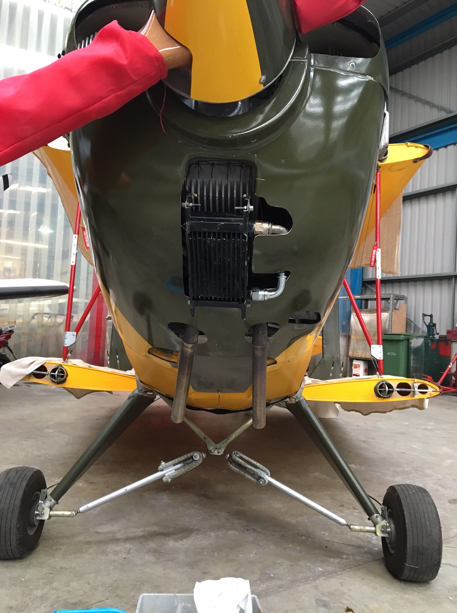
Plan B – was to relocate the underbelly mounted cooler to the front of the ‘plane – right behind the prop .. that should def fix it as there was nothing in the way to prevent a good solid flow over the face of the matrix .. either that or it would demonstrate that THIS wasn’t the problem so at least move me on to the next option.


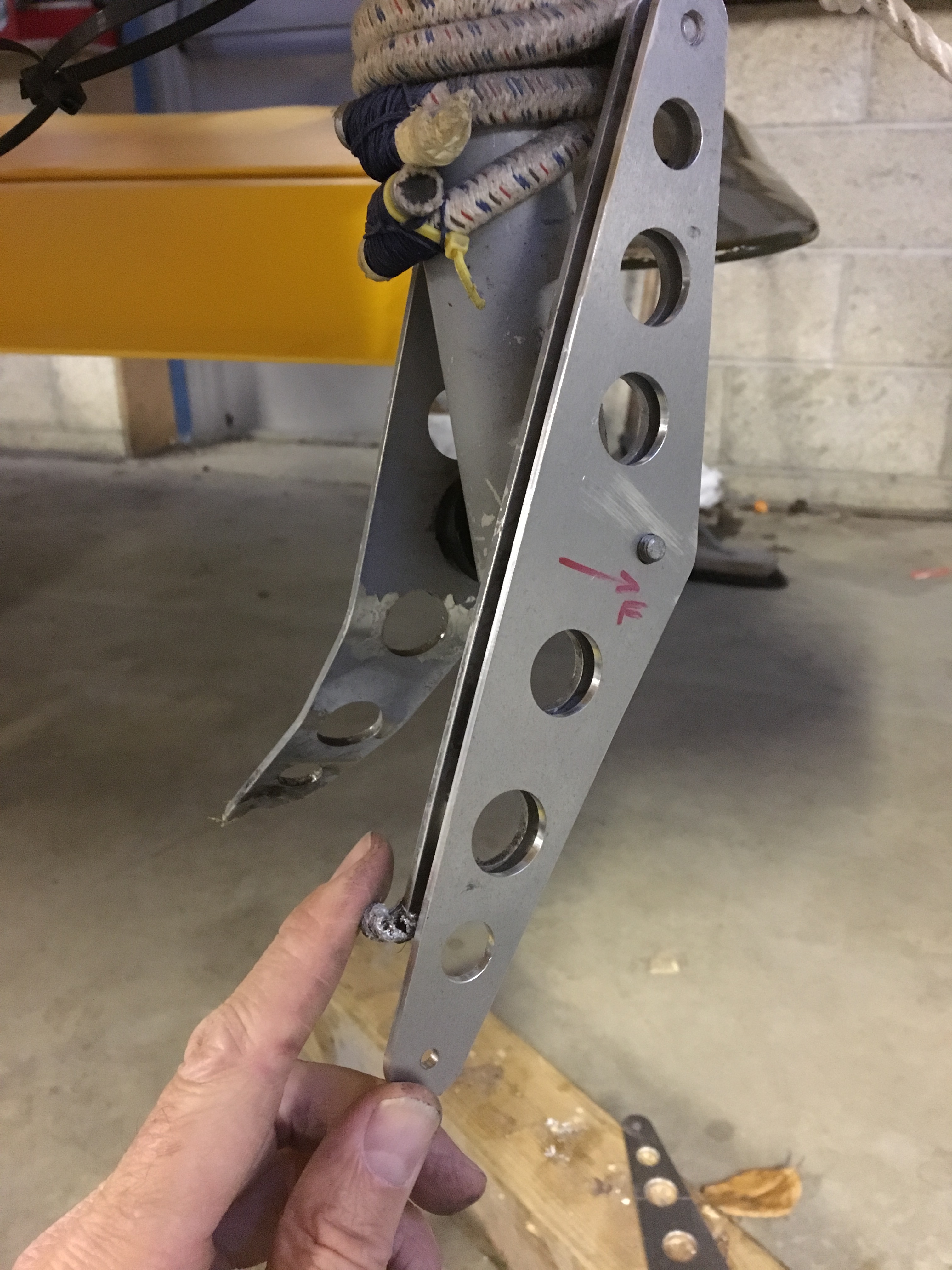
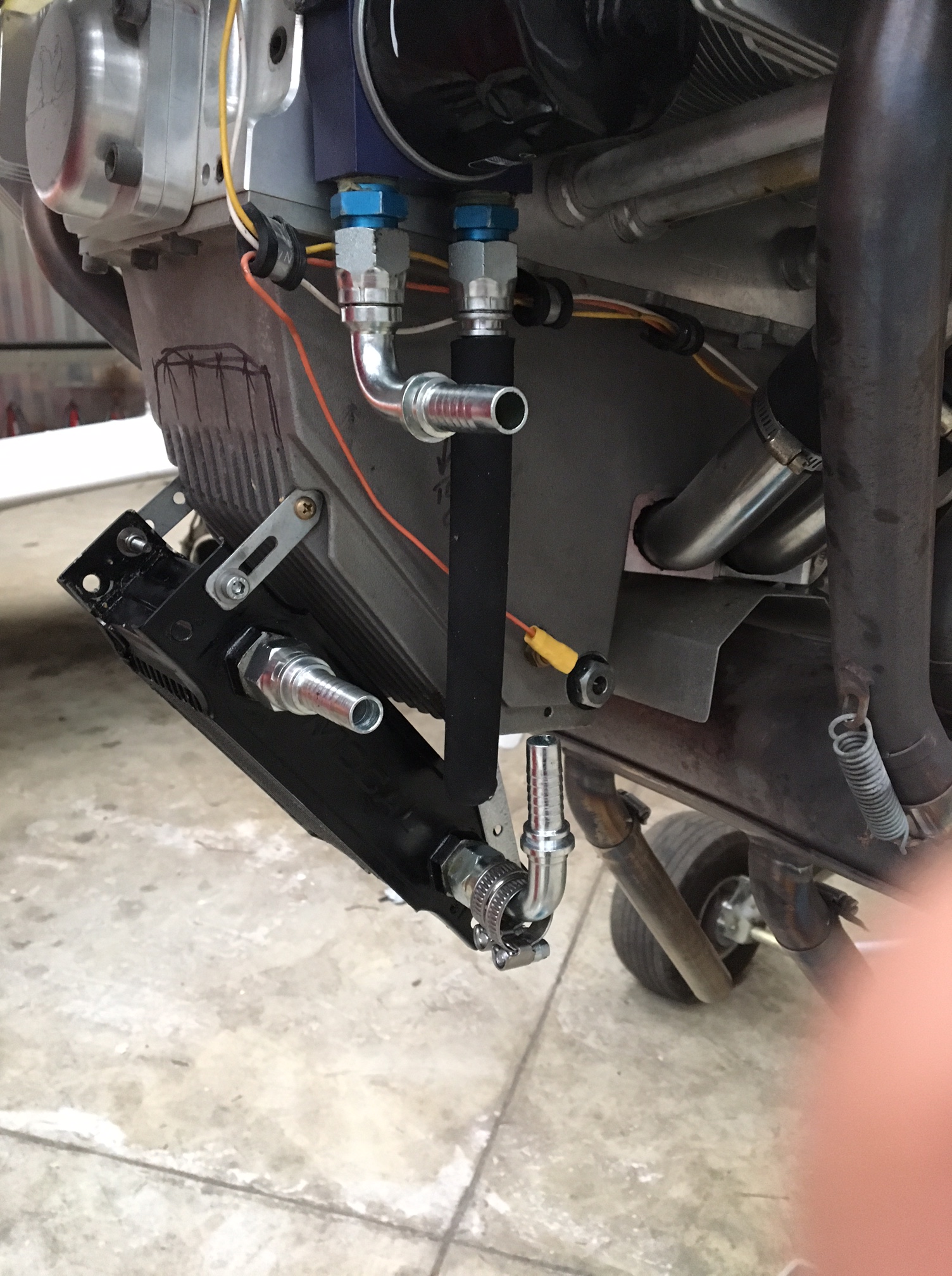
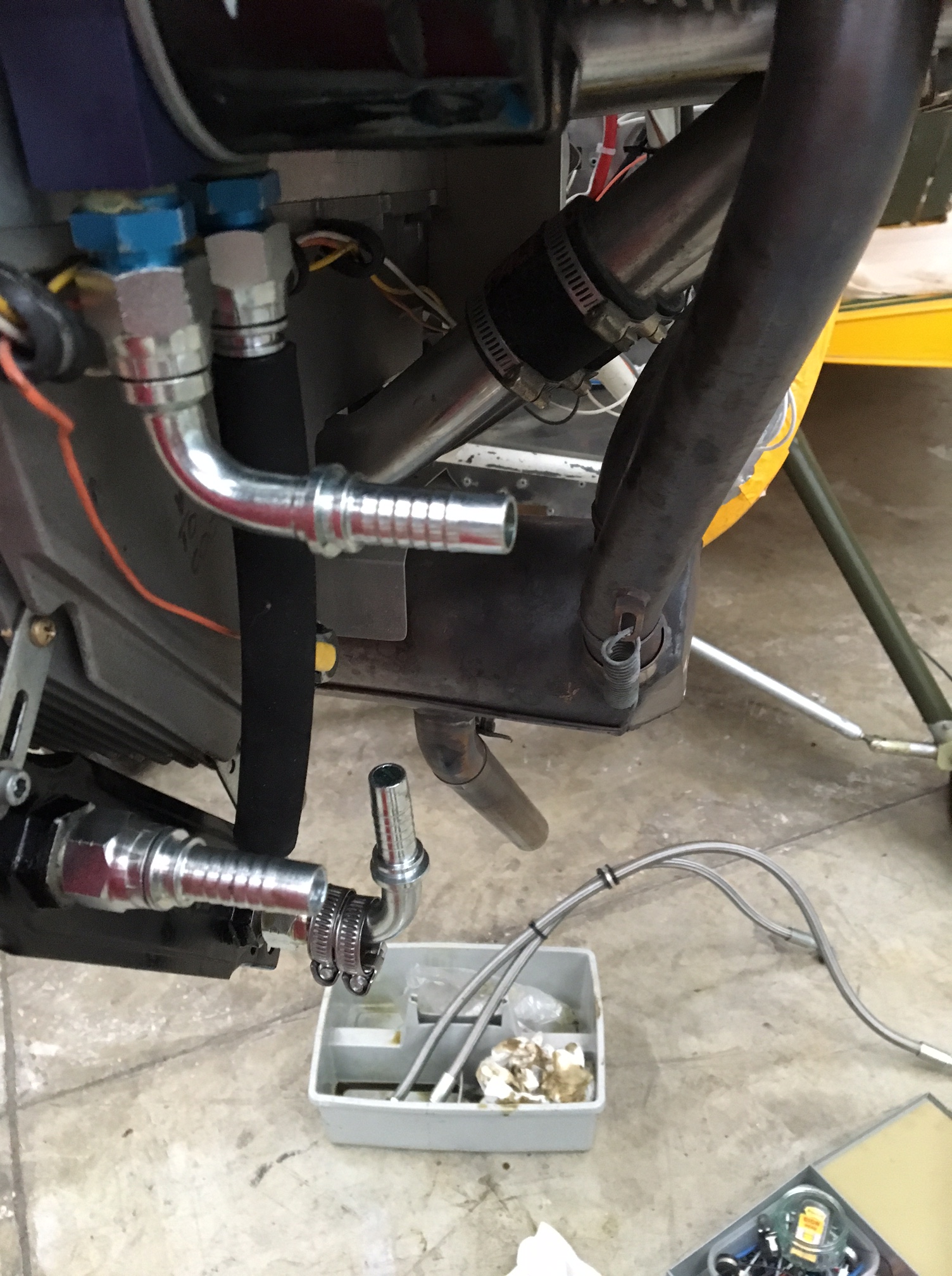
As you can see in the background of the picture I had to ditch my nice braided oil cooler pipes .. once I have established a proper fix I will get some new ones made up to whatever length / shape needed.

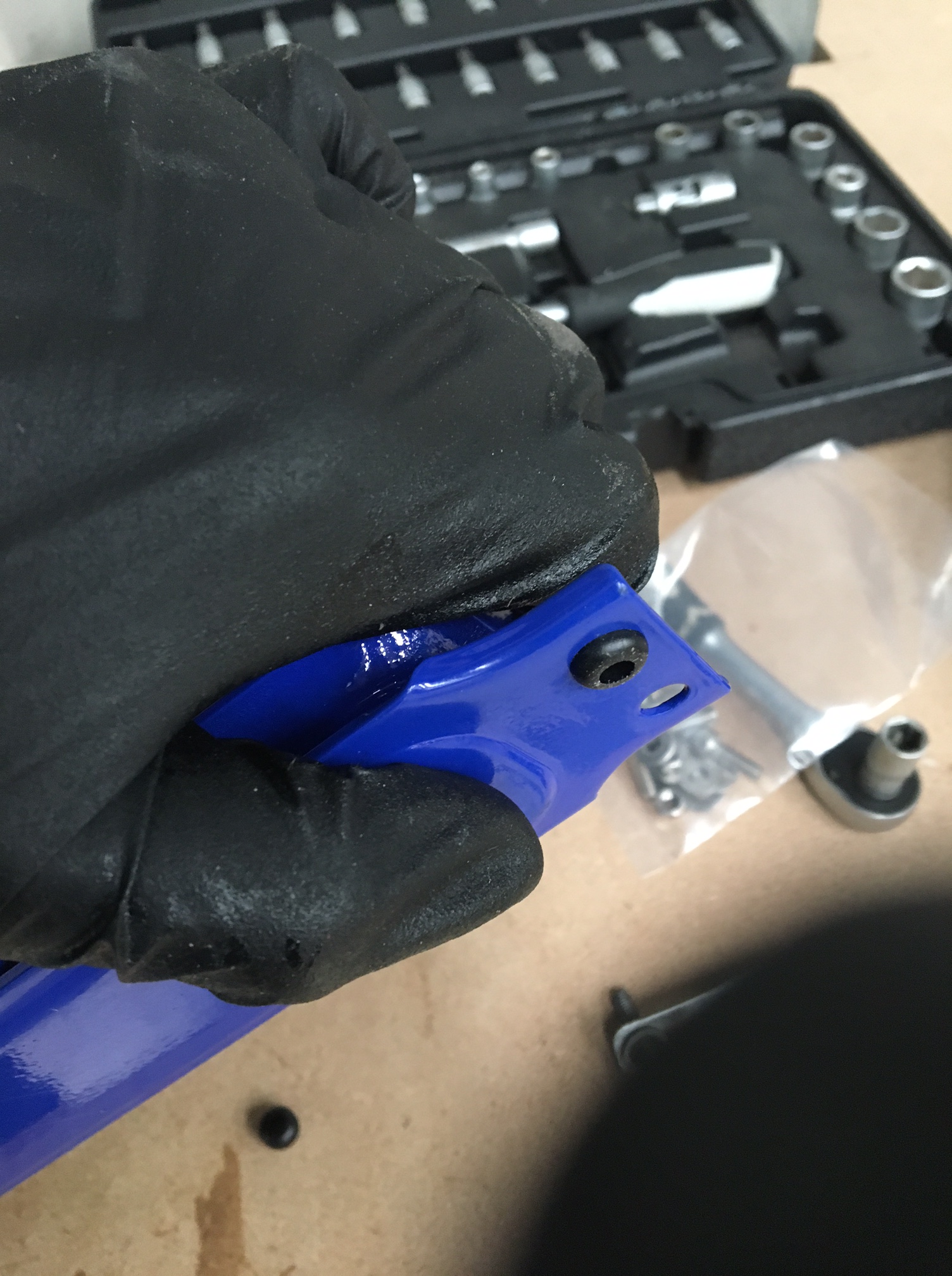
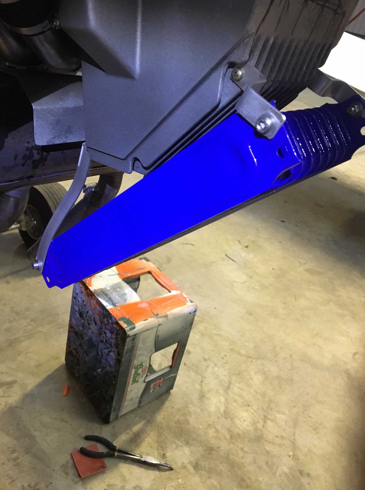
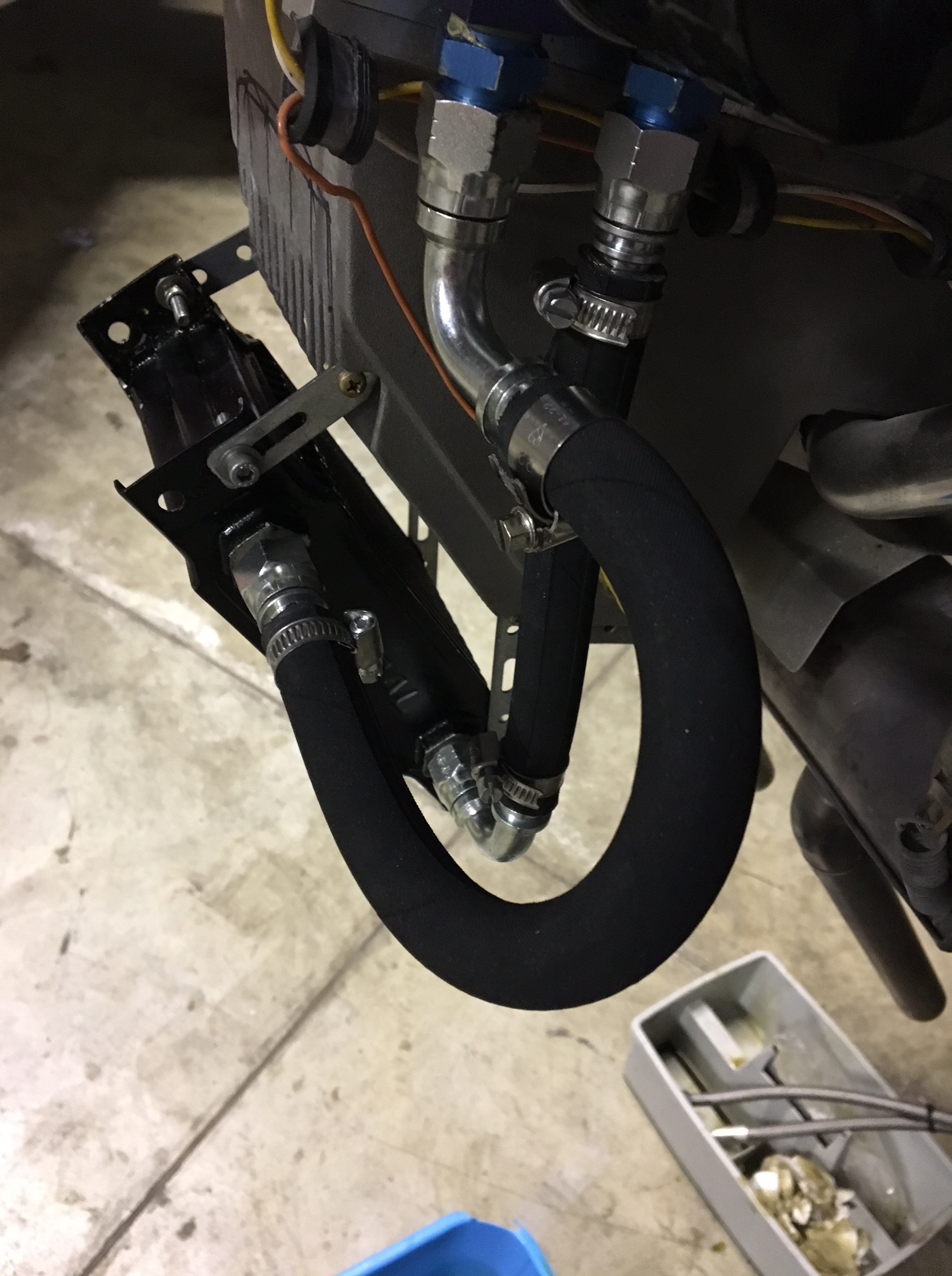
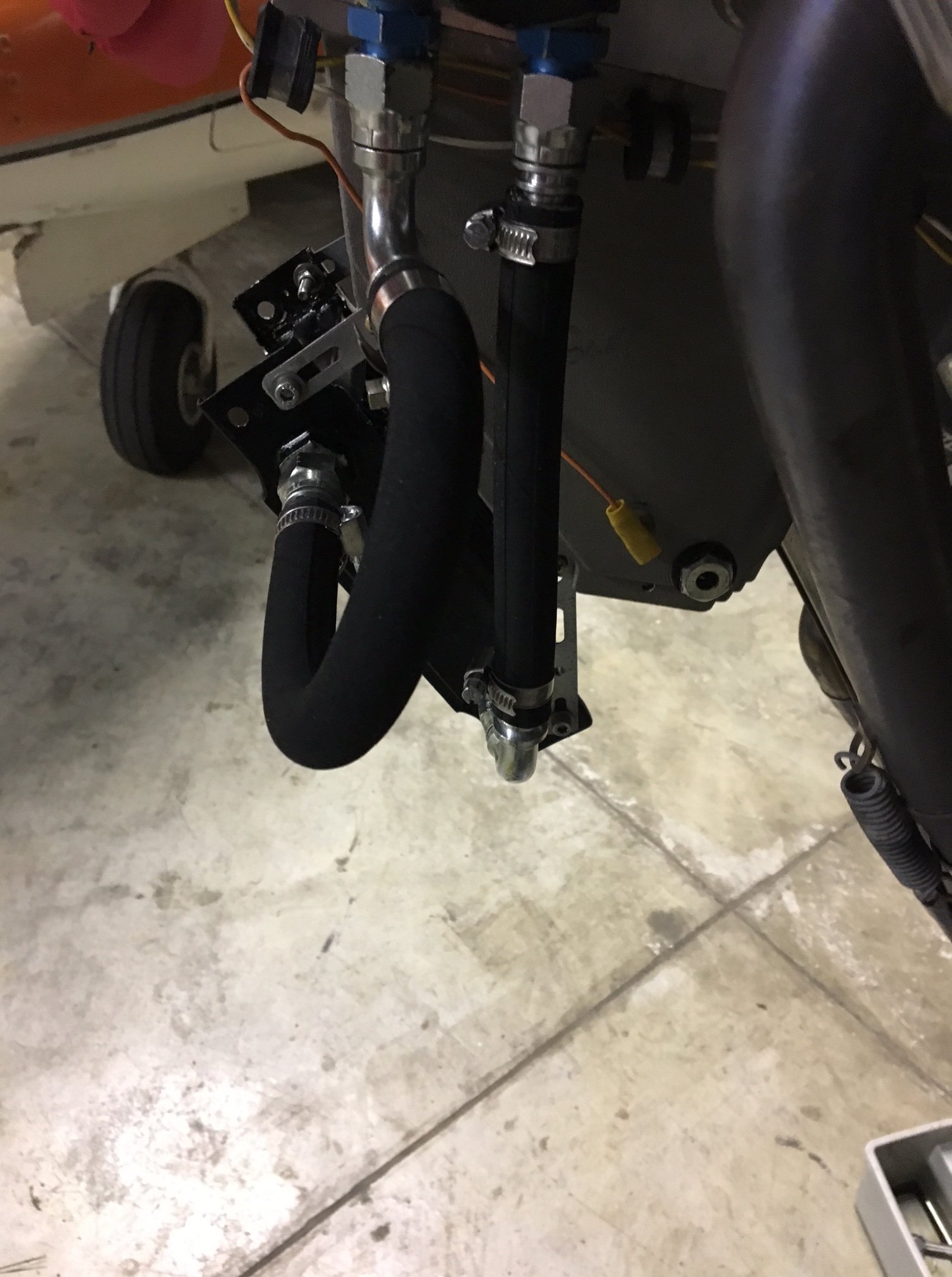
I made up some mounting brackets and moved the old oil cooler into position

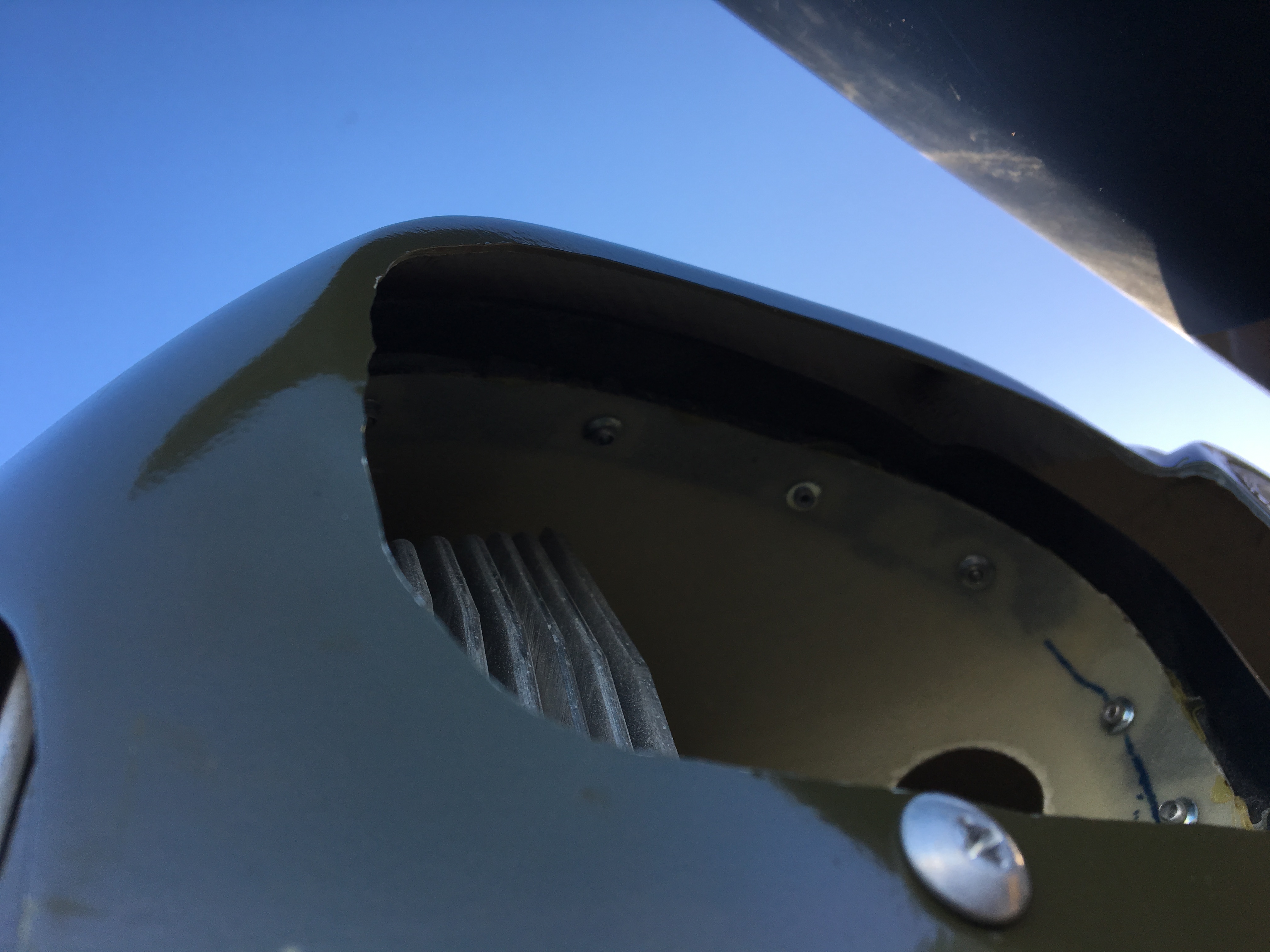
The cowl then took some definite slow and steady fiddling to remove JUST as much as was required to get the cooler AND its pipework in position. Then, with some new wider ducting tape/rubber fill the gaps.

Took the opportunity to remove the original engine top cowl ducts and replace the rubber strips with wider – needed as earlier ‘fettling’ had meant I now had some small gaps between cowl and intakes


T


Cooling planning

Whilst the windy weather has held further testing back I have had chance to share some pictures of my cowling and front end intakes with Paul HS at TLAC.

The upshot is that my original design for the oil cooler housing underneath was not sufficiently shrouded to force the air through the cooler matrix.

The Β setting I had in place left the passing air too much option to simply go by the side or over the top of the matrix !

Have now made two significant changes

  • Add shaped deflectors and shrouds on the front of the matrix
  • Move the matrix back 2 inches
  • Put rear turbulator strips on the rear of the oil cooler tunnel

ok …must learn to count .. That’s 3 things !

image

The setting back of the cooler provided a nice stepped inlet to focus the airflow

image

The deflectors have been added .. One each side and a larger on top. These have been cleco’d for now so that I can test them in flight before securing with rivets


image

The rear turbulator strip encompassed two sides and the Lower edge and present about a 1″ face to the airflow and so should create a reasonable back pressure and support the ram air by introducing a suck from the rear …

Testing due this week and should be proven in two circuits !

Re-cover rear battery access panel

The easy access panel came in handy again and hopefully the last time I will need that for a while πŸ˜€

So – it turns out that moving the relatively small Motorcycle battery all the way to the back was

  1. Great for weight .. needed ZERO ballast to fly her straight off the plan !
  2. BUT hopeless when you expect around 5m of cable to still give you suitable start grunt at the front !

the solution was to re-add the original (now spare ) battery at the front – already had then TLAC mounting plate in position..

Then connect the two in parallel and bingo .. it turns like crazy …

Amazing difference yesterday (27th January) and again after a 20 min run .. leave it for a few mins to cool down then a hot start .. burst into life instantly with barely 1/2 a revolution

img_2100img_2095

Bear back to allow a nice snug fit against the connector

img_2097img_2098

Pick the correct size crimp for the ring connector (16)

img_2099

Neat auto stamping of the crimp size confirms we used the correct connector for the 16 size crimp .. what a clever featureΒ img_2101

Re cover time – need to undo the rudder connection

img_2102img_2103

Align the castellated nut to accept the securing split pin

img_2106

As the whole turtle deck downwards was covered in one continuous sheet I clearly didn’t want to recover ALL of that just because of the rear battery access. So I cut into the Oratex just rearwards of the 45 degree sloping alloy tube support … just rear wards of the β€œG” reg sticker in the picture above .. allowing about a 6” overlap.

The overlap was glued along with the down bar and left to dry overnight. Next day this was ironed into position so making a secure point and leaving a rear section from that point to the rudder post open.

A new piece of material was cut and prepared and glued and fitted the following day to cover this large access panel under the starboard elevator lower fuselage. If required, this section can be removed without affecting the integrity of the rest of the side. In fact you could almost pre cover like this as it would make the single piece sheet a little less unwieldy as it would be that much shorter !

Engine retest – post putting two batteries in parallel

Just awesome starting now …

Wheeled out into blustery conditions but sheltered by the hangers ..ran for 2×20 mins with RPM up to 2400+ for extended periods

  • img_2067
  • img_2089
  • Temperature maintained around 90-102max after some 40 minutes of running
  • img_2088

Switched Oil pressure to PSI .. to make it easier to keep an eye on reading 34 at just over 2400 RPM

January 2017 – Ignition – BINGO !

Well….BINGO …meaty the help of a couple of very good solid knowledgable friends .. Mike (Fleming) and Chris (Sparrow) we now have a truly neat and robust solution .. And tested it this evening …

The original location of the battery (front centre between the P2 legs !) was moved at LAA suggestion which was

  • Good – to remove any ballast at all as the aircraft came out spot on with the battery at the tail
  • Bad – as the cable run to the solenoid so was nearly 5m ! Which .. With a relatively small motorcycle battery turned out to be a real struggle

The solution .. Thank you Mike ! …. Was to reinstall the front battery .. It’s pretty much on the C of G and then wire them in parallel and then review ALL crimped connectors

Then around 1700 this evening mags off, fuel off, throttle set, turns brilliantly !!

Now just need to neaten all cable runs and angles and ensure all booted over joints … Then

GET FLYING AGAIN !!!! Feels like way too long … Good powered engine test first to ensure cooling is in good shape then power climb awaits along with unusual attitude and handling then LAA paperwork off


January 2017 – Ignition review

Crikey .. January has come and is nearly gone but I have tried to get time to work on the starting problem

With the great help of local friends Mike Fleming and Chris ex Jersey Airport we have slowly gone through the system back to front … One quick eliminaton was to connect directly to the front solenoid and effectively jump start her .. This proved that the engine, starter and associated bits were all functioning properly.

It also proved that the problem lay somewhere between front and rear !

I had worked in two solenoid and so we el inmates rearwards from the front… Having first run a dedicated full length black earth from the rear mounted battery to the rear engine bolt. THis meant we wouldn’t have to worry about any earth connections.

After much tooi g and front and using a booster battery to test we could guess that the power drop over the necessary full length body cables (to pickup rear mounted battery) was too great and so we had to find some way of staining the boost and yet still retain the rear mounted battery.

Mile then hit on the idea of leaving the rear battery in position but also mounting a second battery up front in series. This would have the effect of

  • Boosting the supply for start and
  • Providing a high degree of contingency

imageimageimage


Also .. Having reviewed and re-crimped front to rear we discovered that the very front connection to the engine start solenoid had discoloured and had signs of poor initial connection.

This was cut back until we saw fully clear – non discoloured multi core copper cable. This took about 15mm back then it was fine.

The current plan is to retain the rear battery due to LAA spec and weight and balance. Then put the second battery in the original front mounted tray. This will mean we have only around 1m of cable to run to the starter .. The connection should mean that we have two in situ batteries that charge and provide both start and normal avionics support.

Winter testing schedule … Challenges

Well .. The plan was to wrap up and do loads of flying over the winter period … But .. So many London trips with work meant that weekends were always squeezed and then ….

When I got up to pull the Sherwood out and get her all ready the battery appeared to have died ! What a pain … Charged it that evening and tried again the next day only to see it go flat almost immediately and not manage to turn the prop over more than a few painfully slow turns

My good mate Mike (Fleming) kindly bought me a mini trickle charg – the sort that can be left plugged in. Did this but then found same turn problems …

Suspected I had a dead cell so cut back open again and removed the battery … Then tried to sort it whilst I had full access to everything at the rear

Graham (from CIAS) kindly loaned me the jump trolley so that I could discount the battery Β or point to the cabling.

The jump didn’t work … Later found out to be a faulty live jump cable I had !

Mike and I then set about running nose to tail checks with Mikes superb incredibly powerful ‘jump pack’ NOCO GB40 Genuis Boost .. WHAT a piece of kit .. Weighs nothing but could launch a moon rocket !

imageimage

Mike connected at the sharp end and proved that a direct connect at the front solenoid would spin the prop faster than it had ever spun, so we went further rearwards to the second solenoid … This proved quite tricky to reach but again spun really well.

This moved us to the cable between the cockpit and the tail.

image

We moved to the rear and sure we were getting intermittent good and bad turning. Mike started to break down each element and we certainly felt that the isolator switch might be causing a problem.

In any event we felt that the rear mounted battery and its 4-5m of power cable running to the front wasn’t probably a great way of getting a fat bit of power to the engine from a relatively small puny motorbike battery way back in the tail.

We tried connecting the GB40 booster in series to the existing battery and pow .. Loads of turn power …

Next plan .. Decide the best way to resolve low battery force and get airborne again

There are up days and there are not so up days ….

Having had a longish (5-6 weeks) layoff with loads of work and lots of bad weather .. I was actually in Jersey AND it was CAVOK ! and calm !

Duly pulled the ‘plane out and got the engine warmed up with a plan to of the powered climb test for the LAA sign off …

As we got up to temps .. All looked well and taxied up to the far end of the runway 08

Just after lift off the oil temp started to climb rapidly … This problem HAD been fixed by opening up the intake and exit holes and had flown a number of times since … What could be wrong ?

Changed my plan for a large clearing circuit to a close bad weather and then elected for a very tight right hander … The training at Little Snoring really came into its own as we turned a nice tight very short base and back for a soft landing …

The tower had already pressed the alarm button and I had talked to them on the tight right downwind to inform them that it was oil temps rising and couldn’t maintain height.

The full crash tender and blues followed me all the way back to the taxiway and parking at the club after I had run some more engine bursts on the grass to see if it was still ,is behaving in the ground .. Which it was …

Suspect a blocked or seized TOCA oil thermostat valve and chatting with PHS from TLAC suspects the same … Will remove it at the weekend and see if I can test it offline before another ground pre test.

(sent an email to the Jersey SATCO as I think it’s important that they are thanked for their calm support – and fire crew – but also know that I will do something about it before we try again πŸ˜‰

Removed and stripped down the TOCA which is a simple piece if equipment with a bi metallic type unit that, on heating operates an plunger which presses against the small cover plate and pushes the copper looking barrel down the shaft (against the spring) and this then effectively opens up the flow of oil through the now open hole – the hole aligning with the oil feed hole in the engine block.

imageimageimageimageimageimageimage

Unit out and placed in a pan of boiling water and sure enough .. The plunger pushed out about 1.5cm

image

Decided I will try it without this spring and plunger unit in … Simple enough test to fully eliminate it as a problem on extended ground runs BEFORE I try to fly her again.


Blog at WordPress.com.

Up ↑